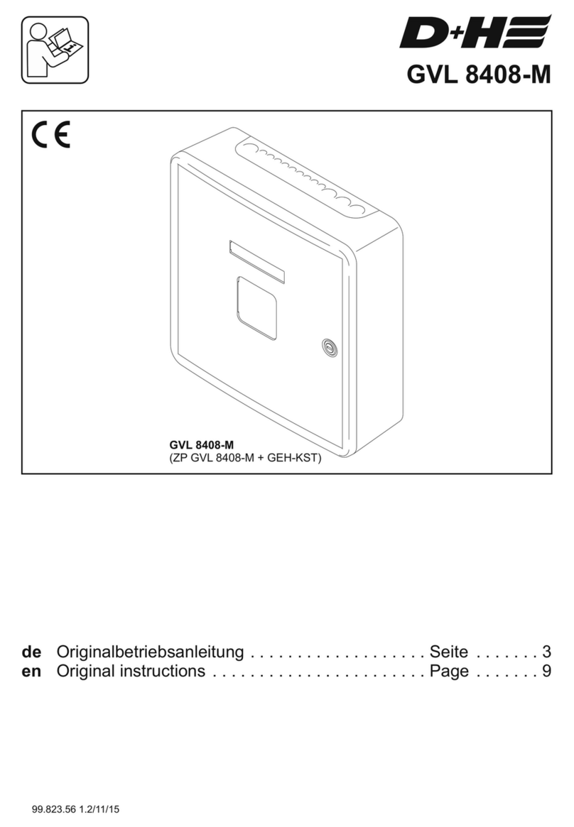
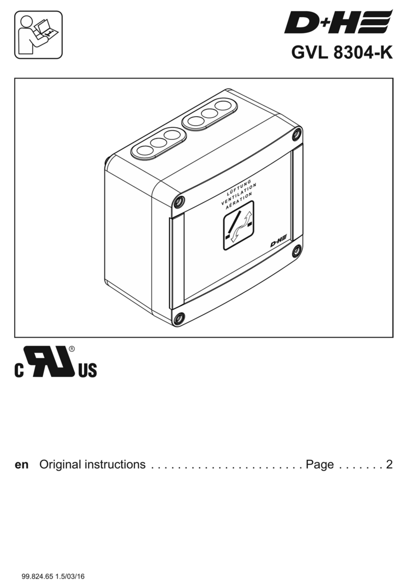
D+H GVL 8408-M User manual

GVL 8408-M
en Original instructions . . . . . . . . . . . . . . . . . . . . . . . Page . . . . . . . 2
99.824.66 1.6/03/16

GVL 8408-M GVL 8408-M
99.824.66 1.6/03/1699.824.66 1.6/03/16
2/8 3/8
English
English
Technical data
Type : GVL 8408-M
Nominal voltage : 115 V AC ± 10%, 60 Hz
Rated power : 240 VA
Stand-by operating : 2.5 W
Class of rating : short-time duty, 20%
Protection class : I
Ingress protection : IP 30
Temperature range : -5...+40°C (23...104°F)
Output voltage : 24 V DC / res. ripple. <10%
Safe output: *
Running current of drives : 6.4 A
Rated current of drives : 8 A
Housing : plastic, white
Dimensions : 12.1'' x 12.1'' x 3.9''
* Please observe:
The output current of the groups 1 ... 6
amounts max. 4 Amp.
The total output current of the control panel,
is limited up to 8 Amp.
Intended use
- ventilation control for small to medium sized
building objects
- for triggering of 24 V DC drives
- 5 ventilation groups, expandable to 6 groups
- 8 A total actuating current - stabilized
- Only for indoor mounting
Performance features
- Ventilation safety function (key operation
OPEN/CLOSE), can be free encoded
- Weather automatic for single groups,
can be switched on and off
- Entry for external control, e.g. timer
- Possibility of connecting rain detector or wind/ rain
detector without supplementary module
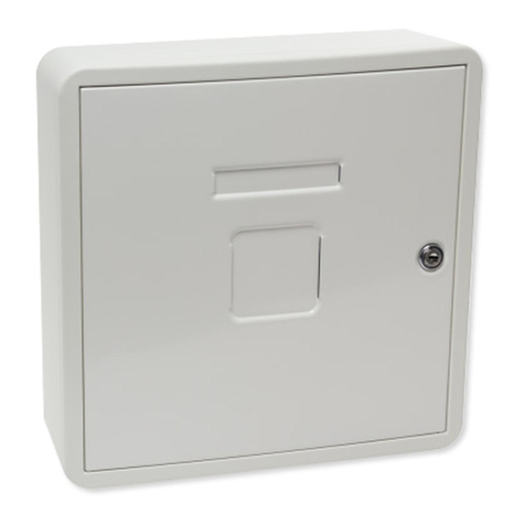
- Plastic housing, surface mounted type with
lockable steel sheet door
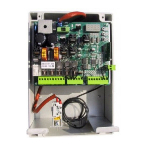
View motherboard
groups
window drives*
vent button* room temp. control* Control panel (GVL 8408-M) rain sensor*
external control*
Example for Application
* optional function extension
(separate components, retrofitable!)
This instruction includes descriptions and
connection plans of components which are not part
of scope of supply of control panel. You can order
these parts and many more separately from your
D+H distributor. Further connecting plans are
available there as well.
Safety notes:
When installing the Ventilation Control Panel (VCP-M 8408), basic safety precautions should
always be followed to reduce risk of fire, electric shock, and personal injury.
Failure to follow these instructions could result in death or serious injury.
Operating voltage 115 VAC!
Connection has to be carried out only by an authorized electrical specialist.
Mounting of the control panel should be carried out by a D+H distributor, whose qualification and
experience is ensured by regular in-house training.
All wiring must be installed by a qualified electrican according to e.g. National Electrical Codes,
NFPA 70 and local codes.
For continued protection against fire, replace only with the same type and rating of fuse.
Only for indoor mounting.
Just use unchanged original D+H parts
For North America:
The International Building Codes have to be observed
For continued protection against fire,
replace only with the same type and rating of fuse.
WARNING
WARNING
fuse mains
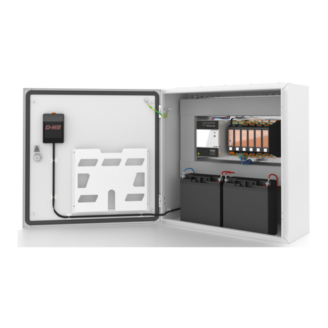
Mulitpoint connector for
further group plug-in unit
LED Power ON
28 - 14 AWG
max. 4.5 lb-in
22 - 12 AWG
max. 6 lb-in
mains connector
S1
F3.15A
T2.5A
S2
F3.15A
S3
F3.15A
S4
F3.15A
S5
F3.15A
Power
115 VAC
www.dh-partner.com
Ventilation control panel
GVL 8408-M
Group 1 Group 2 Group 3 Group 4 Group 5
WARNING
For continued protection against fire,
replace only with the
same type and rating of fuse.
fuse drive
group 1
DIP-switch S1
fuse drive
group 2
DIP-switch S2
fuse drive
group 3
DIP-switch S3
fuse drive
group 4
DIP-switch S4
fuse drive
group 5
DIP-switch S5
group 1-5: 22 - 12 AWG / max. 4.5 lb-in

GVL 8408-M GVL 8408-M
99.824.66 1.6/03/1699.824.66 1.6/03/16
4/8 5/8
English English
115 V AC supply
Connection – Vent buttons and Window drives
Line lengths and
cross sections
see page 4
4 5 6 7
GVL 8408-M
–
Mot.b
Mot.a
X
OPEN
CLOSE
L (open signal, only LT 84-U-SD)
LT MOT
123
Vent button
(e.g. LT 84-U-SD)
LP
Mot.b
Mot.a
24 V DC
Window Drives
Mot.b
Mot.a
4
GVL 8408-M
+G
Az
Zz
–
X1
1 2 3
External contact
for central closing
(e.g. rain detector)
Drive group 1 ... 5
Ask your local D+H partner for further connection examples.
Wiring plan (Paragon)
115 V AC, 60 Hz
to further ones
see line lenghts and cross sections
window drive control panel
vent button
ca. 4 ft above
upper edge
firm flooring
4x AWG 20
4x AWG 20
4x AWG 20
rain sensor
3x AWG 14
room temperature
control
Line lenghts and cross sections
total current
0.5
787
1312
2100
1
394
656
1050
1.5
262
427
699
2
197
328
525
2.5
157
262
420
3
131
213
351
3.5
112
180
299
4
98
164
262
ft
ft
ft
type
2x AWG 16
2x AWG 14
2x AWG 12
total current
0.5
240
400
640
1
120
200
320
1.5
80
130
213
2
60
100
160
2.5
48
80
128
3
40
65
107
3.5
34
55
91
4
30
50
80
m
m
m
type
2x 1,5 mm²
2x 2,5 mm²
2x 4 mm²
Encoding of group
Following functions can be adjusted for each group separately with DIP switch S1 - S5 on motherboard
of control panel and on group plug-in unit, if available.
The delivery state of all DIP-switches is OFF.
1 = ON Drives CLOSE up to final position by single pressing on respective vent button.
1 = OFF Drives are closing only so long as the vent button is pressed.
2 = ON Drives OPEN up to final position by single pressing on vent button.
2 = OFF Drives are opening only so long as the vent button is pressed.
3 = ON Drives are automatically closed by trigger of function „Central CLOSE",
e.g. by rain detector or room temperature control.
3 = OFF Drives can be closed only by pressing the respective vent button.
4 = ON Drives are automatically opened by trigger of function „Central OPEN",
e.g. by room temperature control.
4 = OFF Drives can be opened only by pressing the respective vent button.
The input current of the
connected window drives
shall not exceed 4 Amp.
WARNING
Output voltage 24 VDC!
Do not run cables together with power lines!
In case of a cable with ground wire
(e.g. green / yellow) this must not be used!
L
N
PE
115 V AC, 60 Hz
cable tie for
strain relief
external
control
2x AWG 20

GVL 8408-M GVL 8408-M
99.824.66 1.6/03/1699.824.66 1.6/03/16
6/8 7/8
English English
Mounting of drive:
Because of varied possiblilties for choosing drives,
Please take mounting informations from relevant
instructions for use of the respective drive.
Moving direction of drives:
Change poles of wires of the drive supply („Mot.a"
and „Mot.b"), when moving direction is wrong.
Window drives (Accessories)
Connection – Rain sensor and Room temperature control
< optional >
rain
Wind
Wind
–
+
124357689
R
W
WRG 82
S 1/1
S 1/2
P3 P4
+G
–
Zz
Az
1 2 3 4
GVL 8408-M
L
N–
Z
A
X
Mot.a
Mot.b
1234567
GVL 8408-M
LT MOT
LT 84-U +
LT 84-U-W
close
–N
open
PPS
VRS 10
rain
–
–
+24V
21 3 4 5 6
R
insert bridge!
insert bridge!
* Connect lead directly when no automatic switch available.
In this case the manual operation is out of function.
Mot.a
Mot.b
Mot.a
Mot.b
Line lengths and
cross sections
see page 4
branch box
branch box Only if wind detector or rain detector available:
If the weather automatic is switched on via vent button LT 84-U-W
(optional), the system will automatically close in case of wind or rain.
The system will not automatically open again, if wind or rain has stopped.
Opening of the system for ventilation via vent button.
The weather automatic can be switched-off at vent button LT 84-U-W
(optional), if gap ventilation is required in case of bad weather.
Gap ventilation is not possible in case of bad weather, if no vent button
LT 84-U-W available.
Operation - Weather automatic
The input current of the
connected window drives
shall not exceed 4 Amp.
WARNING
ST OP ST OP ST OP
Operation - Day-to-day ventilation
Open: Close: Stop:
Ventilation button required.
STOP
Automatic
on/off
LT 84-U-W
Electrical devices, accessories, batteries and packa-
ging should be sorted for environmental-friendly
recycling. Do not dispose electrical devices and
batteries into household waste!
Only for EC countries:
According the European Guideline 2012/19/EU for
waste electrical and electronic equipment and its
implementation into national right, electrcal devices
that are no longer usable must be collected separa-
tely and disposed of in an environmentally correct
manner.
Disposal
Maintenance and cleaning
Inspection and maintenance has to be carried out
according to D+H maintenance notes. Only original
D+H spare parts may be used. Repair is to be carried
out exclusively by D+H.
Wipe away debris or contamination with a dry, soft
cloth.
Do not use cleaning agents or solvents.

D+H Mechatronic AG
Georg-Sasse-Str. 28-32
, Germany22949 Ammersbek
: +49 239Tel. 40-605 65
: +49Fax 40-605 65 254
E-Mail: info@dh-partner.com
www.dh-partner.com
© 2012 D+H Mechatronic AG, Ammersbek
Technische Änderungen vorbehalten. /
Rights to technical modifications reserved. 99.824.66 1.6/03/16
Table of contents
Other D+H Control Panel manuals
