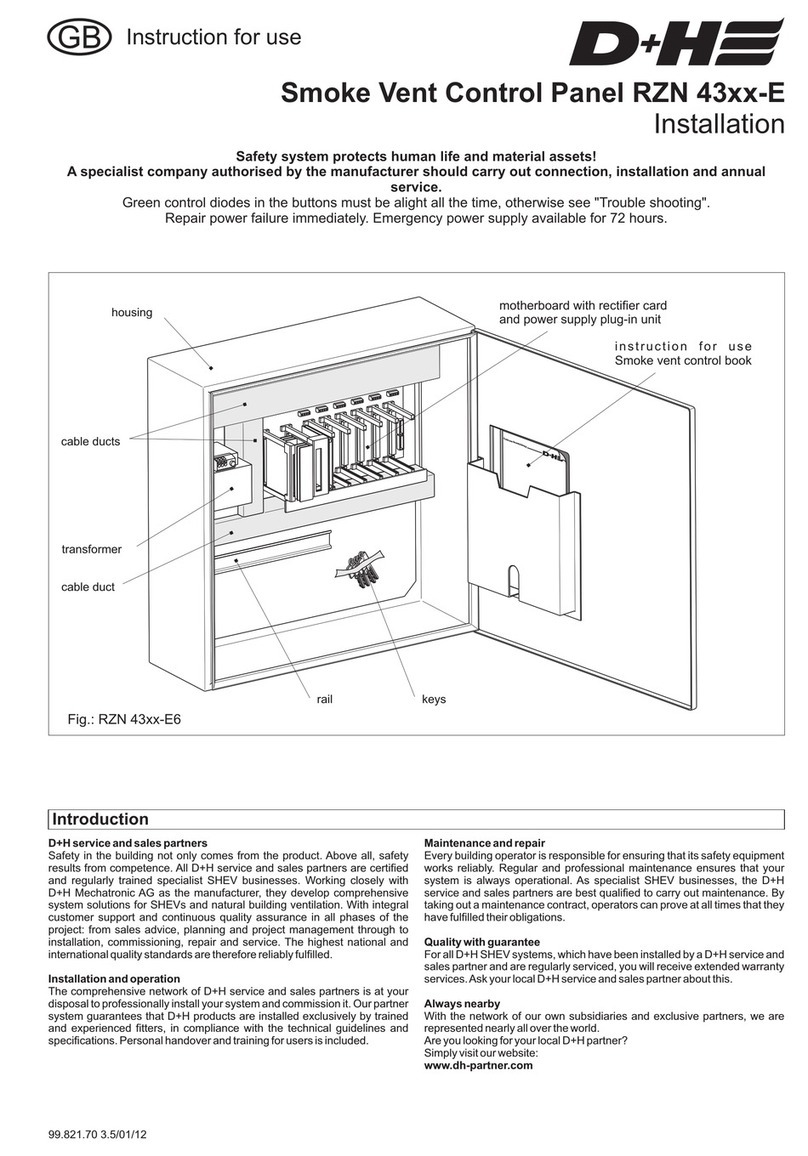
D+H RZN 4503-T User manual

99.823.83 1.1/11/08
© 2008 D+H Mechatronic AG, Ammersbek
Alle Maße in Millimeter. / All sizes in millimetre.
Technische Änderungen vorbehalten. /
Rights to technical modifications reserved.
D+H MechatronicAG • Georg-Sasse-Str. 28-32 • 22949Ammersbek • Tel. 40-605 65 239 • Fax 40-605 65 254 •D- +49 +49 www.dh-partner.com
1/12
smoke ventsmoke vent
Instruction for use
Safety system protects human life and material assets!
Once a year functional testing by a specialist company authorized by the manufacturer.
Connection, mounting and functional testing by a
specialist company authorized by the manufacturer.
Green control diodes in the buttons must constantly be on,
otherwise see "Information for Starting".
Repair power failure at once. Emergency power supply for 72 hours.
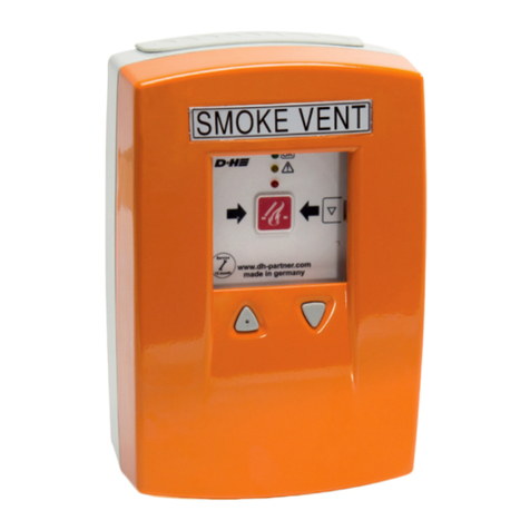
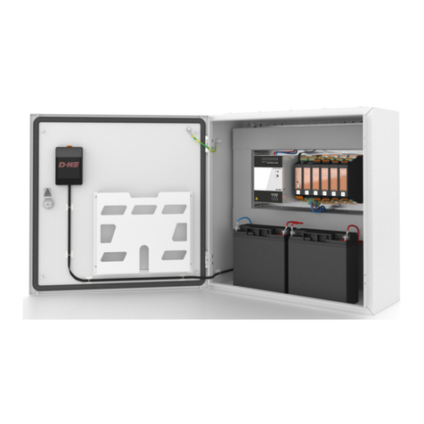
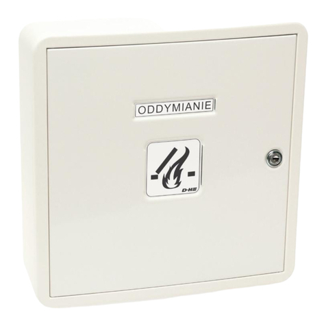
Smoke vent button control panel RZN 4503-T
There are guarantee for all D+H products from date of verified handing over of the system
up to maximal 3 years after date of delivery, when mounting and starting has been carried out by a
D+H authorized
D+H guarantee is expired in case of connection of D+H components with external systems or
with mixing of D+H products with parts of other manufacturers.
2 years
distributor.
Guarantee

2/12
99.823.83 Rev.: 1.1
Once a year by a specialist company
authorised by the equipment manufacturer.
Renew test badge. Update logbook.
The respective current D+H maintenance
instructions should be followed.
AD+H authorised company has been specially
trained by D+H for carrying out this
maintenance competently and will be
automatically provided with the latest
maintenance instructions.
Following tests must be carried out during
maintenance:
- External examination and inspection of
system components
- Measuring of insulation resistances
- Checking of all relevant power supply
units.
- Functional testing of connected system
components.
- Logging of competent execution of
maintenance and identification in
accordance with directions.
Information
An overdue maintenance of the system will be
indicated by the control panel after about
14 to 16 months. The yellow diode in the
control panel and in the smoke vent button
RT 43-H will start flashing.
A malfunction in the smoke vent system will be
continually indicated by the extinguished
green control diodes in the smoke vent
buttons.
After the maintenance time is expired (ca. 14 to
16 months), the ventilation function OPEN can
be interrupted depending on the presetting of
the service timer. Reset can be carried out by a
specialist company only who has been
authorized by the appliance manufacturer.
Content
Maintenance
Rated voltage : 230 VAC, 50 Hz
(+10%, -15%)
Rated capacity : 100 VA
Capacity con -
tion standby : < 5 W
Interfering
emission : EN 61000-6-3 (08.02)
Res. to jamming : EN 61000-6-2 (08.02)
Protective
category : I
Fire resistance : -5 to +40 °C
Protective system: IP30
Class of rating
- Monitoring : Continuous duty
- Emergency
state/ ventilation : Short-time duty
Output voltage : 24 VDC / res. ripple <5%
Safe output
- rated current : 3 A (30% power-on time)
Dimensions : 156x83x232 (WxDxH)
D+H Highspeed (HS) drives will be
sump
maximum no. of fire detectors: 14 pcs.
maximum no. of smoke vent buttons: 8 pcs.
Technical Data
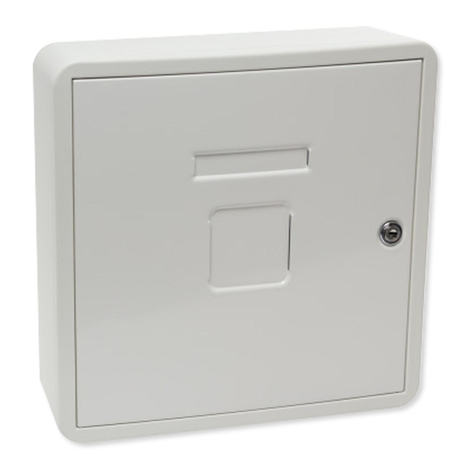
1 x pre-assembled control panel
1 x housing
1 x breaking glas
3 x hanger bolt
6 x hexagonal nut M5 DIN 6923-8
1 x mounting tool
1 x sheet "smoke vent" different languages
2 x key
pre-assembled
Scope of delivery
Guarantee
Technical Data, Maintenance, Scope of delivery
..................8
LEDs und functions
..................................................................................................................................1
..........................................................................2
Introduction................................................................................................................................3
Overview operating elements.....................................................................................................4
Operating...............................................................................................................................5-7
Extended functions...................................................................................................
.....................................................................................................................9
Cable und Emergency Supply...................................................................................................10
Starting.....................................................................................................................................11
Examination.............................................................................................................................12

3/12
99.823.83 Rev.: 1.1
Regulations for Hazard Detection Systems VDE 0833, Guidelines for Electrical Systems VdS
2221, VDE 0100, DIN 18232 for Smoke and Heat Ventilation Systems, and the regulations for
mains supply connection from the local fire-authorities and the energy supply company must be
observed.
Important Regulations
Introduction
Smoke and heat ventilation systems (SHEVs) are very important elements of structural
preventive fire protection.
Only regular and professional maintenance guarantees the necessary and permanent
functional safety.
D+H Mechatronic AG
D+H Mechatronic AG
D+H MechatronicAG
D+H Mechatronic AG
D+H MechatronicAG
D+H Mechatronic AG
Smoke and heat ventilation systems are preventive fire protection appliances. They fulfill
important functions in case of fire: safeguarding human life by providing a smoke-free layer which
keeps evacuation routes free for the fire brigade. Consequential damages caused by fire gases
are reduced, and therefore, significant material assets are often protected against destruction.
Precondition for this is that the systems will function absolutely reliably in the case of fire. Only
electrical specialist companies are authorised to install these systems. They have electrical
specialist staff with relevant experiences in installing hazard detection systems or smoke and
heat ventilation systems. Only these can take on the responsibility that the system will function
and can ensure product liability for the whole system (see Product Liability Law BGBL.I S.2198
and BGB (Bodily injury, compensation for damage)).
Therefore, regular maintenance and checking of functional readiness is imperative and must be
ensured. These standard requirements are demanded in accordance with regulations of the DIN,
of the Association of German Insurer against damage of property (VdS) and the respective local
authorities. It is recommended that maintenance work should be carried out by authorised
specialist companies only.
Maintenance and installation of smoke and heat ventilation systems and system components
constructed and distributed by should be carried out by authorised
companies. All partners are qualifyed as authorised companies, which
regularly take part at in-house trainings to ensure their qualification and experience.
Smoke and heat ventilation systems must be reviewed at annual intervals by authorised
companies in accordance with DIN 18232 part 2 paragraph 10.2, and VDE 0833 part 1 paragraph
5.3.4 for hazard detection systems and in accordance with the manufacturer guidelines.
In accordance with DIN VDE 0108 part 1 paragraph 9.1.1, emergency supply accumulator
batteries (lead accumulator batteries) must be checked every six months by a person briefed and
once a year, maintenance must be carried out by an authorised company. Accumulator battery
types which are used for smoke and heat ventilation systems must be VdS
approved and released for use by in Smoke and heat ventilation systems.
In accordance with DIN 18232 part 2 paragraph 10.2 the tests must be logged in an operations
book, which the operator/building owner must present to the building supervision authority on
request. This operations book is available at (part no.: 68.700.13)
Maintenance that has been carried out must be logged in a
maintenance and testing confirmation.

4/12
99.823.83 Rev.: 1.1
OK
M
Po
wer
Po
wer
2
30
VAC
2
30
VAC
B
atte
ry
B
atte
ry
Det
ectorLine
Det
ectorLine
Drive
Drive
Group
Group
Module
Module
Connector
Connector
X2
OFF
Service
X1
Service
X1
0
Reset
/
I
S1
8
1ON
www.dh-partner.com
Service
12 month12 month
www.dh-partner.com
RAUCHABZUG
RAUCHABZUG
RAUCHABZUG
Pictograms
Smoke and heat vent alarm
Control panel O.K.
Fuse actuator
Mains drive
Vent button function "ON"
Vent/ smoke vent function “CLOSE”
Fault
Charging voltage controller
Battery
LED
system O.K.
DIP switch
(factory-set
see p. 9 and 11)
LED mains
LED-alarm
LED group fault
LED-battery
fault LED earthfault
Reset line
LED line fault
LED general fault
LED "not CLOSED"
ventilation button CLOSE
alarm button
alarm reset button
ventilation button OPEN
Overview
smoke ventsmoke vent
www.dh-partner.com
Service
12 month12 month
green control diode
(system O.K.)
yellow (flashing)
(fault)
control diode
red
(alarm)
control diode
Reset button
(masked)
alarm button
ventilation button OPEN
with LED "not CLOSED"
ventilation button CLOSE

5/12
99.823.83 Rev.: 1.1
OK
Po
wer
2
30
VAC
B
atte
ry
Det
ectorLine
Drive
Group
Module
Connector
X2
OFF
Service
X1
0
Reset
/
I
S1
8
1ON
www.dh-partner.com
Service
12 month
www.dh-partner.com
1. 2. 3.
4.
RZN/RT
RAUCHABZUG
RAUCHABZUG
3.
1. 2.
RAUCHABZUG
RAUCHABZUG
RZN/RT
4.
click
1. 2.
4.
RAUCHABZUG
RAUCHABZUG
3. RZN/RT
RZN 4503-T Operation
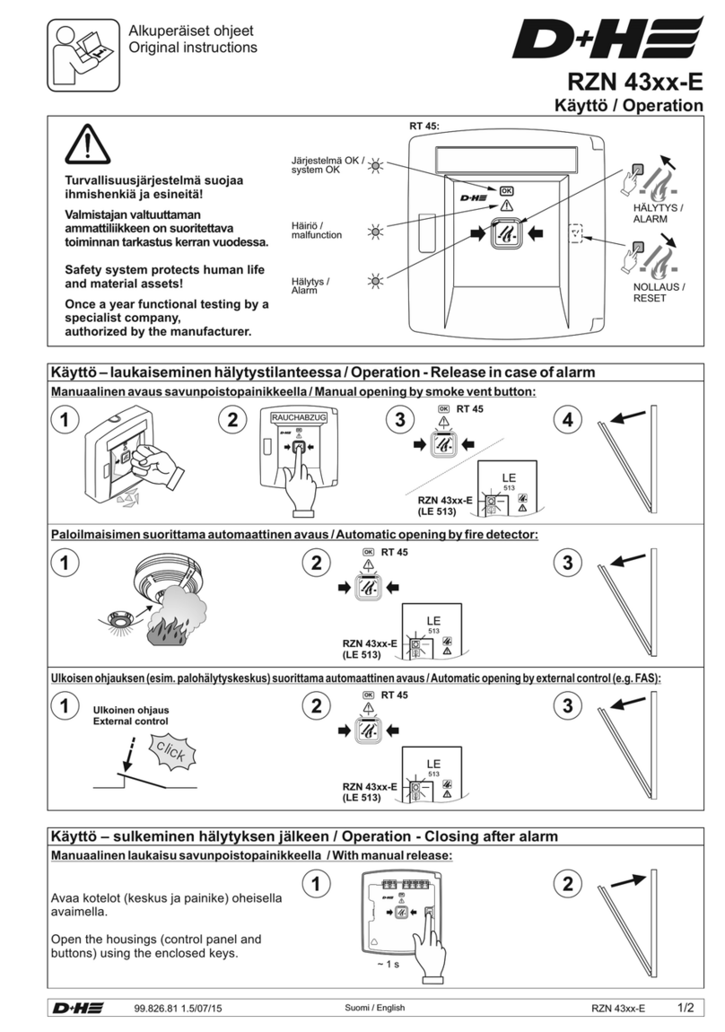
Release in case of alarm
Manual opening by smoke vent button:
Automatic opening by fire detector:
or
and
Automatic opening by external control (e. g. fire alarm control panel (FACP)):
and
smoke vent
www.dh-partner.com
Service
12 month

6/12
99.823.83 Rev.: 1.1
2.
1.
3.
3.
*
RAUCHABZUG
www.dh-partner.com
Service
12 month
RAUCHABZUG
www.dh-partner.com
Service
12 month
RAUCHABZUG
www.dh-partner.com
Service
12 month
Closing after alarm
RZN 4503-T perationO (continuation)
With manual release:
Opening the housing (RZN / RT) with supplied key.
Automatic opening by external control:
see
DIP-switch S1
(page 8)
hold for OFF /
shortly tap for ON
3s
or
or
* function is deactivatable by
D+H PDA service tool
In case of automatic release by external control (e. g. FACP):
or

7/12
99.823.83 Rev.: 1.1
RAUCHABZUG
www.dh-partner.com
Service
12 month12 month
RAUCHABZUG
www.dh-partner.com
Service
12 month12 month
RAUCHABZUG
www.dh-partner.com
Service
12 month12 month
In case of power failure:
Emergency closing
In case of non-resettable alarm:
hold for OFF3s
see
DIP-switch S1
(page 8)
or
Day-to-day ventilation
or
or
or
RZN 4503-T perationO (continuation)
customer
service

8/12
99.823.83 Rev.: 1.1
Extended Functions
The following functions are set by the DIP switch S1 on the PCB at the control panel, or can be set by a
D+H distributor with the D+H PDA service tool:
S1.1 ON =
CLOSE
S1.2 ON =
OPEN
S1.2 OFF= OPEN
Storage operation
S1.1 OFF= Key operation
CLOSE
Storage operation
Key operation
S1.3 ON = activated
S1.3 OFF = deactivated
S1.4 ON = activated
S1.4 OFF = deactivated
S1.5 ON = activated
S1.5 OFF = deactivated
S1.6 ON = activated
S1.6 OFF = deactivated
S1.7 ON = activated
S1.7 OFF = deactivated
S1.8 ON
S1.8 OFF
Programmable by
D+H Distributor with
D+H PDAservicetool
Storage operation
Key operation
Line fault = alarm
Group fault on alarm
OPEN-running time limitation in ventilation operation
Ventilation time limitation
Power failure CLOSED
vent buttons activitated
vent buttons deactivitated
deactivated
deactivated
deactivated
activated
activated
Press ventilating button 1 x shortly. The drives/ NSHEVs will open to
their final position.
The drives/NSHEVs will open only as long as the ventilating button is
pressed.
In case of a line fault the control panel will be switched to alarm and the
smoke vent opens (e.g. at an interrupted button line or missing
terminal resistor).
In case of a group fault the control panel will be switched to alarm and
the smoke vent opens (e.g. in case of an interrupted drive line or
missing terminal module).
If the vent button is actuated in direction OPEN, the drives/ NSHEVs
open for 30 s (factory-set). This running time can be edited by D+H
PDA servicetool. Only possible in conjunction with storage operation
in CLOSE-direction.
The drives/ NSHEVs will automatically close again after the time set
(factory-set 10 min). This time can be edited by the D+H PDA
servicetool. Only possible in conjunction with storage operation in
CLOSE direction!
In case of power failure the drives will close. Only possible in
conjunction with storage operation in CLOSE direction!
Integrated are
Integrated are
OPEN running time retriggering (factory-set: )
Group CLOSE in case of alarm (factory-set: )
Two smoke detectors dependency (factory-set: )
Smoke detector alarm remote reset (factory-set: )
Lamp test
Alarm re-clocking (factory-set: )
Hint: In case of alarm the smoke vent is triggered with an OPEN pulse
every 2 minutes for a duration of 30 minutes according to VdS 2581.
For this, the drive must be protected against blockage according to
VdS 2580 par. 4.7. .All D+H drives meet this precondition.

9/12
99.823.83 Rev.: 1.1
12345678
ON
LEDs und Functions
on off
flashing off
off on
LED line fault LED OK LED general fault
Line fault
Deactivated line
Servicetimer is up
flashing
flashing
flashing
LED Indication
Line switch-off
hold3stoswitch off
line /
tip on to switch on
If the LED line fault flashes, the line is
switched off, e.g. for service reasons. You
cannot activate the control panel in this
status. In case of an actual line error the
LED line fault is permanently on.
DIP switch
factory-set
Programmable by
D+H Distributor with
D+H PDAservicetool
Functions
not changeable
The signalling relay features the following signals:
(factory-set: signalling relais 1="alarm"
signalling relais 2 = "general fault")
Accumulator
Group output
If wind or rain detector is connected.
Do not ventilate via smoke vent button because otherwise there is danger
of damage by wind or water.
optional vent button
LT 43U-W Gap ventilation
is not possible if no vent button LT 43U-W is
available LT 43U-W
pre-alarm, terminated alarm, delayed alarm
general fault, accumulator fault, line fault, group fault, power failure
earth fault, passing on of "central CLOSE", "ResetAlarm" as pulse,
group closed longer = x s
Charge (temperature-guided)
Monitoring: presence, final discharging voltage
Discharge control: In case of power failure and total discharge of accumulator,
the control panel will switch off. In this case, smoke vent is no longer possible.
In this case the LED System O.K. and the LED general fault are not on.
Three minutes after the motor group has been operated in OPEN or CLOSE
direction, the potential between Mot.a and Mot.b is switched to zero potential.
If the respective sensor releases, the group of the control panel will close. Wind
velocities can be adjusted to 4-6 Bft.
If the alarm is released by a smoke and heat vent system, the system will open
regardless of wind and rain.
The weather automatic can be switched-off with an
, if gap ventilation is required in case of bad weather.
in case of bad weather,
. If the weather automatic is switched on via vent button , the
system will automatically close in case of wind or rain. The system will not
automatically open again, if wind or rain has stopped. Opening of the system for
ventilation via vent button.
For further information see information for use VRS 10 REM 42 and WRG 82.

10/12
99.823.83 Rev.: 1.1
Install and feed separately from supply mains.
Mark cable and terminal box red.
Provide for separate electric circuit.
Mark fuses.
Plug covering cap over mains binder on
motherboard of control panel.
Connecting cable: NYM-I3x1.5
Connecting load: 100 VA
Emergency power supply for 72 hours. Use VdS and D+H approved storage batteries only.
1 x min. 12 V / 3.2 Ah (Type 8)
If alarm devices are connected:
Total current of 3 A must not be exceeded. If necessary, reduce drive current. Emergeny
power supply time of 72 hours can be shorter in case of fire alarm. Total standby current must
not exceed 0.25 A.
Weak Current Lines
24 V - Emergency Supply
230 VAC - Supply
The smoke vent control panel is designed for
opening smoke vent devices which operate by
thermal ascending force and by automatic fire
recognition devices (thermal detector, smoke
detector). They release either self-acting or
manual by smoke detectors at an early stage of
a fire, and remain in opened position without
further power consumption. In these cases,
functioning preservation of the electrical line
system is required only at an early stage of fire.
Protected wiring is required with protection
against mechanical damages according to DIN
18232 section 2.5.5 paragraph 4.
Cable from the smoke vent control panel to
connection of drive. Drive lines have a
monitoring wire in which fire recognition
devices (thermal maximal detector e.g. THE)
can be looped-in:
- Safety line with functional conservation
xxx E30*, according to DIN 4102 or standard
guidelines for line systems MLAR.
Control Cable (Group):
Cable for D+H Smoke and Heat Vent Systems
Detector Cables (Line):
Cables through areas not monitored:
The detector cables are monitored for short
circuit and for break.
The opening device is automatically triggered
and opens up in case of fault when DIP
switch 7 is ON.
Smoke vent button cable and cable of
automatic detectors:
- weak current sheathed flexible cable YR
6 x 0.8
or
- house wiring cable IY(ST)Y 4 x 2 x 0.6
An increased time of functioning of the cable
can be required when drive lines are installed
through building parts which are not
monitored.
- Safety line with functional conservation
xxx E90*, according to DIN 4102 or standard
guidelines for line systems MLAR.
(see supplementary sheet 1 to DIN VDE
0108)
* Notice: No type designation is given
for these cables because of a large
variety on the market. Please consult
your D+H distributor about these

11/12
99.823.83 Rev.: 1.1
Information for Starting
Carry out the following sight and performance checks to switch on the smoke and heat vent
control panel.
yes
no
yes
no
yes
yes
yes
yes
yes
yes
no
no
no
no
no
no
All cables
connected?
All necessary moving loads connected?
Smoke vent components are line-monitored.
Factory-set?
(DIP switch)
10 k resistor in
smoke vent button?
Ω
10 k resistor in
fire detector?
Ω
Terminal module
2 x 47 kΩ in branch box?
Connect mains.
Mains control on?
Connect accumulator
lines. Control on?
Performance check alarm/reset and ventilation.
Smoke vent flap
opens and closes?
Partial or incomplete connection of components can
cause malfunction.
Check the following connections: mains 230 V, drives,
smoke vent buttons, if necessary fire detectors and
vent buttons. See wiring and connection plans
Mounting and Installation.
Set DIP switch S1 on
motherboard as follows:
Resistor must be cramped in electric last button on
binding posts 3/ 8 (RT 43-H) or binding posts 3/ 7
(RT 42). See Mounting and Installation.
Resistance must be cramped in last or only fire detector
on binding post 2 and 4 (type FO/FT). Resistance remains
in control panel between binding post RM 1 and 2, when
no fire detector available.
See connection M .ounting and Installation
Cramp terminal module on last or only drive in branch box
on wire 5 yellow orange, 6 black, 7 black.
See M .ounting and Installation
Check line safety fuse in distribution box and fuse mains in
control panel.
Mains still not available or line switch
on "0", see line switch-off page 9, or one of fuses faulty.
Try changing poles in drive.
factory-set:
12345678
ON

12/12
99.823.83 1.1/11/08
Examination
Preparation:
Information
Inspection:
Smoke vent button:
Notify user that the system is out of operation
before starting with inspection.
Notify user about false alarms.
Interrupt or switch off monitored alarm
indication and remote controls.
An overdue maintenance of the system will be
indicated by the control panel after about 16
months. The yellow control diode in the control
panel as well as in the smoke vent button
RT43-H will start flashing.
A malfunction in the smoke vent system will be
continually indicated by the extinguished
green control diodes in the smoke vent
buttons.
After the maintenance time is expired (ca. 14 to
16 months), the ventilation function OPEN can
be interrupted depending on the presetting of
the service timer. Reset can be carried out by a
specialist company only who has been
authorized by the appliance manufacturer.
Check all appliances and cable connections
for outer damage and dirt accumulation.
Fire detectors, smoke vent buttons, smoke
vents and so on must not be impaired in their
function by goods in storage or structural
changings.
Open smoke vent button .
Press red button, red display diode is on in
button and control panel.
Smoke vent must open.
Press masked button (1 s), red display
diode extinguishes in button and control
panel.
Smoke vent must close.
Automatic fire detectors:
Release smoke detector individual by D+H
smoke detector tester, as an alternative by
cigarette smoke (response delay circa 20 s).
Red display diode must be on.
Smoke vent must open.
For closing wait until there is no more smoke in
detector.
Reset line in control panel (switch off/ switch on
line), red display diode
extinguishes in button and control panel.
Press masked button in control panel or in
smoke vent button. Smoke vent must close.
The line can also be directly reset via smoke
vent button, if remote reset is activated. For
this, press masked button in smoke vent
button (for 1 s).
Red display diode extinguishes in button
and in control panel.
In case of severe dirt accumulation visible from
outside, send detector
in for maintenance.
Release external control.
Smoke vent must open.
Open contact in external system for closing, for
example by resetting of fire detector system.
If smoke and heat exhaust do not automatically
close, press masked button in smoke vent
button (1 s). Red display diode
extinguishes in button and control panel.
Smoke vent must close.
Detach fuse MAINS in power distributor.
Green mains indication diode on control
panel must not be on.
Repeat functional testing.
Green control diode in smoke vent buttons
must not be on.
If "power failure-CLOSE" is activated with PDA
servicetool, the group will automatically.
Reconnect fuse MAINS in power distributor
install another one and
close
.
External control (optional):
Emergency supply:
Every six months and after repair by a specialist or staff, who has been introduced to
the task.
Eliminate failings at once. Keep control book.

RZN 4503-T
Montage und Installation
Mounting and Installation
99.823.87
1.1/11/08
D+HMechatronicAG • Georg-Sasse-Str.28-32 • 22949Ammersbek • Tel. 40-60565239 • Fax 40-60565254 •D- +49 +49 www.dh-partner.com 1/2
© 2007 D+H Mechatronic AG,Ammersbek
Alle Maße in Millimeter. / All sizes in millimetre. Technische Änderungen vorbehalten. /
Rights to technical modifications reserved.
RAUCHABZUG
3.
Akku anschliessen / connect accumulator
1.
2.
Montage / Mounting
2
345
Leitungsverlegeplan (Muster) / Wiring plan (example)
Leitungslängen und Querschnitte / Line lengths and cross sections
Die angegebenenAderzahlen und Querschnitte beziehen sich nur auf die benötigten Leitungen.
Bei Verwendung einer Leitung mit Schutzleiter (grün/gelb) wird dieser nicht mitgezählt und darf
nichtbeschaltetwerden./
Number of wires and cross-sections indicated refer to required lines only. In case of using a line
with earthed conductor (green/ yellow), this one will not be counted in and must not be wired.
Gesamtstrom /
total current 0,511,522,53A
3x1,5 mm² 240 120 80 60 48 40 m
3x2,5 mm² 400 200 130 100 80 65 m
*5x2,5mm² 800 400 260 200 160 130 m
1x mind. /
12V / 3,2 Ah (Typ / 8)
1x at least
type
230V 50Hz
nicht abschaltbar /
not possible to
switch off
Brandmelder 24VDC
(z.B. FO 1362 oder FT 1262) /
Fire detector 24VDC
(e.g. FO 1362 or FT 1262)
Lüftungstaster 24VDC
(z.B. LT 43) ca. 1,2 m über OKFF
(bei UP bauseits 55mm UP - Dose) /
Vent button 24VDC
(e.g. LT 43) circa 1,2 m above upper
edge firm flooring (at flush type
at side 55mm flush socket)
JY (St) Y
2x2x0,6
zu weiteren /
to further ones
JY (St) Y
2x2x0,6
siehe Kabelverlegetabelle /
Hauptbedienstelle
Rauchabzugstaster /
Main control
smoke vent button
(RT43-H/N)
Nebenbedienstelle
Rauchabzugstaster /
Secondary control
smoke vent button
(RT43-H/N)
Kontakt Fremdansteuerung
z.B. Brandmeldezentrale /
Contact external control
e.g. fire alarm system
JY (St) Y
4x2x0,6
JY (St) Y
4x2x0,6
JY (St) Y
2x2x0,6
Zentrale RZN Aufputz
(230VAC / 24VDC)
in der Nähe der RWA-Klappe. /
Control panel RZN surface type
(230VAC/ 24VDC) in proximity of
smoke vent flap.
Antrieb(e) 24VDC
an Rauchabzugsklappe(n)
(Leitung in einer UP-Verteilerdose
enden lassen). /
Drive(s) 24VDC
at smoke vent flap(s)
(Lines must end in flush mounted
distribution box.)
1234567
Platinenansicht / Motherboard view
Sicherung ANTRIEBE /
F 2.5 A
fuse DRIVES
Schutzkappe* /
covering cap*
Netzanschluss /
power supply
1234567
Wind- Regenmelder 24VDC
(z.B. WRG 82) /
Wind- rain transmitter 24VDC
(e.g. WRG 82)
JY (St) Y
2x2x0,6
1
3x
1.
2.
Vorher:
Stockschrauben in
Kreuz eindrehen! /
Before:
screw hanger bolt
into tool!
1,36m
ab OKFF /
from top of floor
* ufsetzen/Schutzkappe a
*put on covering cap
3x
Hinweis: Schriftzug bitte aus beiliegendem
Sprachenbogen heraustrennen und einsetzen. /
Hint: Please detach name plate from enclosed
language sheet .and put in
Kabelausbruch /
cable breakout
Linie /
line
Netz /
mains Gruppe /
group
110
183
203
6
Querschnitt /
(mm²)
cross section einfache Kabellänge / (m) x Gesamtstrom /
80
plain cable length total current
=
*2 Adern je Antriebsleitung parallel schalten. /
*Connect in parallel 2 wires for each drive line
zu weiteren /
to further ones
see cable wiring table *
*
Melderelais 1 /
signalling relay 1 Melderelais 2 /
signalling relay 2
-
+
A
K
S
M
Z
B
: notversorgtesPotential-
: notversorgtesPotential+
nichtnotversorgtesPotential+
: Sammelalarm
: Kontrolle
: Sammelstörung
: AnsteuerungHaftmagnete
: Eingang,ZentralfunktionSchließenderGruppe
: BMZ-Eingang
N-
N+
: nichtnotversorgtesPotential-
:
Klemmenbelegung E-Platz / Clamp assignment E-Slot
-
+
N+
A
K
S
M
Z
B
: emergency-supplied electric potential -
: emergency-supplied electric potential +
: electric potential +, without emergency supply
:
: ontrol
: general malfunction
: magnetic clamp
: input, central function, closing of group
: BMZ input
N- : electric potential -, without emergency supply
generalalarm
c
control

99.823.87
1.1/11/08
D+HMechatronicAG • Georg-Sasse-Str.28-32 • 22949Ammersbek • Tel. 40-60565239 • Fax 40-60565254 •D- +49 +49 www.dh-partner.com
2/2
© 2007 D+H Mechatronic AG,Ammersbek
Alle Maße in Millimeter. / All sizes in millimetre. Technische Änderungen vorbehalten. /
Rights to technical modifications reserved.
Anschluss Rauchabzugstaster
Standardanschluss RT 4x-H / -N
Fremd-
ansteuerung /
external excitation Brandmelder /
fire detector
Arbeitskontakt /
operating contact
Alarmwiderstand /
alarm resistor
10k *W
10kW
1kW
out
in
letzter /
last
Rauchabzugstaster /
smoke vent button
RT 43-N (RT 42)
+Alarm / alarm
273164
OK
V
V
wahlweise /
optional
out
in
erster bis
vorletzter /
first to
second
before last
Linie / line
–
–
1210 < wahl-
weise / >optional
ERMRT
345678
-
Kontrolle / control
Alarm / alarm
zu/close
RT 43-H (RT 42-H)
RT 43-N
(RT 42)
10kW
Alarm / alarm
-
Störung / malfunction
27
83164
Alarm /
alarm
zu/close
RD
GN
YE
23164
75
10k *W
Sammelstörung / *general malfunction
* nur bei /
RT 4x-H only at
jeweils erster
bis vorletzter
RWA-Taster /
first to
second before
last smoke vent
button each
jeweils
letzter
RWA-Taster /
every last smoke
vent button
RZN 4503-T
BMZ- / - ResetFACP
12
RM
RT 43-N (RT 42) RT 43-N (RT 42)
-
-
227733116644
12345678
RZN 4503-T
–
–
Alarm / alarm
Sammel-
störung /
*
general
malfunction
RM/RT
RT 43-H (RT 42-H) RT 43-H (RT 42-H)
RT 43-N
(RT 42)
RT 43-N
(RT 42)
10kW
10kW
Alarm / alarm
Alarm / alarm
-
-
Störung / malfunction
22
77
8833116644
Alarm /
alarm
2233116644
77
55
bauseitige
Rangier-
verbindung /
Shunt
connection
by customer
Parallelanschluss RT 4x-H / -N
Anschluss Antriebe und Lüftungstaster / Connection of drives and vent buttons
MOT
Zentrale /
control panel
Mot. b
765
Mot. a
Überw /.
M
M
br
bl
br
bl
Abzweigdose
am Motor /
branch box
on motor
weitere Abzweige
gleichartig schalten /
connect further
branchings alike
Abzweigdose /
branch box
- Versorgungsadern
zweigenparallelab/
- wirddurchalleKabelbis
zumGruppenendedurchgeschleift./
Mot. a und Mot. b
Überwachung
- Supply wires and branch
off parallel
- is looped through
all the cables up to the group end.
Mot. a Mot. b
Monitoring
Anschluss bei Leitungsabzweig / Connection with line branch
Anschluss Brandmelder / Connection of fire detectors
Anschluss eines Brandmelders / Connection of one fire detector
Anschluss mehrerer Brandmelder / Connection of several fire detectors
Anschluss Haftmagneten / Connection of magnetic clamps
* Bei Verwendung von Linienschaltungen mit 2-Melder-Abhängigkeit, darf der Widerstand
nicht eingesetzt werden. /
* The resistor must not be used when line connections with 2-detector dependency
are employed!
-+
-+
- + N- N+ A K S
Unterbrechertaster /
Interrupter button
Haftmagnet /
Magnetic clamp
Haftmagnete / 24V
(max. 200mA* Gesamtstrom /
)
Magnetic clamps
overall power
Ausgang bei
Netzausfall
spannungsfrei! /
Low tension side
in neutral position in
case of power failure!
MZB
*Der maximale
Gesamtstrom darf nicht überschritten werden.
*overall power must not be exceeded
Linie /
line
-
einziger Brandmelder /
180R
1
2
3
4
5
6.
7
*
Endwiderstand /
terminal resistor
10K
single fire detector
Linie /
line
-
erster Brandmelder /
first fire detector zweiter bis vorletzter
Brandmelder / letzter Brandmelder /
last fire detector
180R
1
2
3
4
5
6.
7
*180R
1
2
3
4
5
6.
7
*180R
1
2
3
4
5
6.
7
*
Endwiderstand /
terminal resistor
10K
second to second before
last fire detector
Linie / line
Linie / line
jeweils
letzter
RWA-Taster /
every last smoke
vent button
Rauchabzugstaster /
smoke vent button
Kontrolle / control
zu/close
Linie / line
Linie / line
+Kontrolle / +control
zu/close
Linie / line
Linie / line
* nur bei /
RT 4x-H only at
+Alarm / alarm
+Kontrolle / +control
zu/close
Linie / line
Linie / line
+Alarm / alarm
+Kontrolle / +control
zu/close
Linie / line
Linie / line
Rauchabzugstaster 1. Strang /
smoke vent button 1st Lane Rauchabzugstaster 1. Strang /
smoke vent button 1st Lane
Rauchabzugstaster 1. Strang /
smoke vent button 1st Lane Rauchabzugstaster 1. Strang /
smoke vent button 1st Lane
Kontrolle / control
zu/close
Linie / line
Linie / line
Kontrolle / control
zu/close
Linie / line
Linie / line
RD
GN
RD
GN
zu/close
zu/close
RD
GN
YE
zu/close
RD
GN
YE
zu/close
Störung / malfunction
Kontrolle / control
zu/close
Linie / line
Linie / line
RZN 4503-T
Lüftungstaster /
vent button Antriebe /
drives
LT 43 (-SD)
Querschnitte und Leitungsarten
siehe unten /
cross sections and type of lines,
see below
zu/close
–N
Aufmeldung / OPEN signal
auf / open
erster bis vorletzter /
first to penultimate drive
LT 43
Aufmeldung (wahlweise) /
OPEN signal (optional)
–N
Überwachung /
monitoring
Mot.a
Mot.b
5671234
LT MOT
L
L
P
P
braun /
brown
blau / blue
Branderkennungselement /
thermal detector
THE 4
BK
BK
OR
2x47kW
EM 47K
letzter Antrieb /
last drive
bauseitige Abzweigdose /
branch box by customer
Antriebe mit
HS Funktion /
drives with
HS function
braun / brown
weiss / white
orange (-HS)
zu/close
auf / open
bauseitige Abzweigdose /
branch box by customer
Abzweigdose /
branch box
moni-
toring
Abzweigdose
am Motor /
branch box
on motor
jeweils
letzter
RWA-Taster /
every last smoke
vent button
jeweils
letzter
RWA-Taster /
every last smoke
vent button
V
V
wahlweise /
optional
jeweils erster
bis vorletzter
RWA-Taster /
first to
second before
last smoke vent
button each
Alarm /
alarm Alarm /
alarm
Alarm /
alarm
Other manuals for RZN 4503-T
2
Table of contents
Other D+H Control Panel manuals
