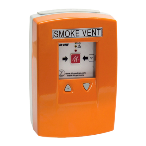
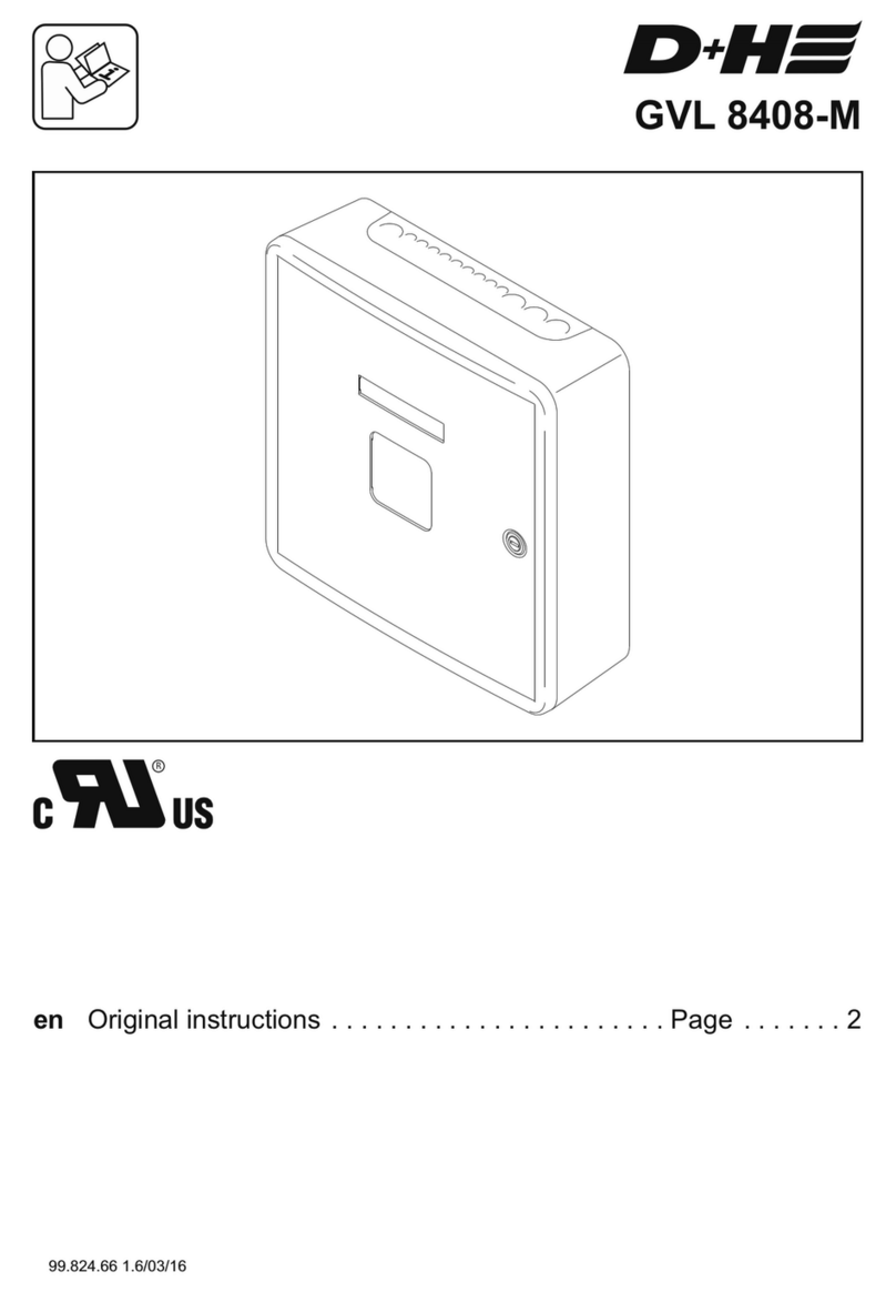
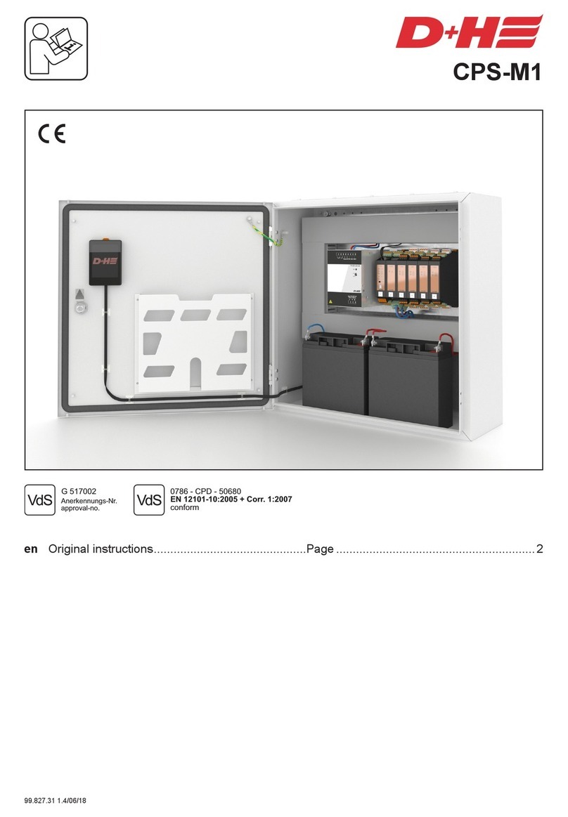
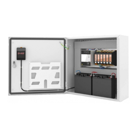
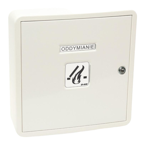
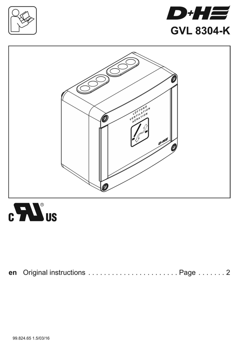
D+H GVL 8408-M-UL User manual

GVL 8408-M-UL
en Original instructions . . . . . . . . . . . . . . . . . . . . . . . Page . . . . . . . 2
99.828.04 1.0/06/19

GVL 8408-M-UL GVL 8408-M-UL
99.828.04 1.0/06/1999.828.04 1.0/06/19
2/12 3/12
English
English
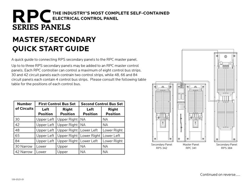
Intended use
- Ventilation control for small to medium sized
building objects
- For triggering of 24 V DC drives
- 5 ventilation groups
- 8 A total actuating current - stabilized
- Only for indoor mounting
Example for Application
* optional function extension (separate components, retrofitable!)
This instruction includes descriptions and connection plans of components which are not part of
scope of supply of control panel. You can order these parts and many more separately from your
D+H distributor. Further connecting plans are available there as well.
WARNING
Performance features
- Ventilation safety function (key operation
OPEN/CLOSE), can be free encoded
- Weather automatic for single groups,
can be switched on and off
- Entry for external control, e.g. timer
- Possibility of connecting rain detector or wind/ rain
detector without supplementary module
- Plastic housing, surface mounted type with
lockable steel sheet door
Delivery contents
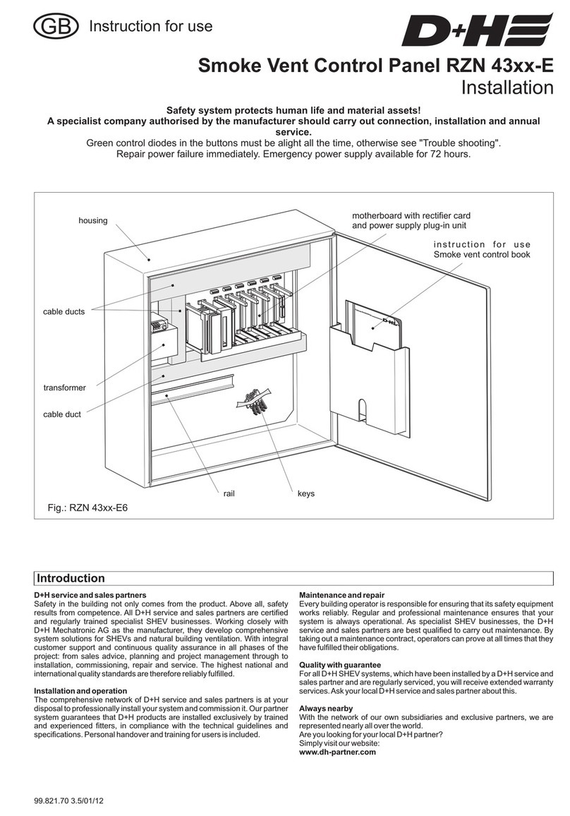
Ventilation control panel including control Board,
plastic housing, replacement fuses and instructions
for use.
groups
window drives*
vent button* room temp. control* Control panel (GVL 8408-M-UL) rain sensor*
external control*
Safety notes:
- Read all safety warnings, instructions, illustrations and specifications provided with this
product.
- Failure to follow all instructions listed below may result in electric shock, fire and/or serious
injury.
- Save all warnings and instructions for future reference.
- When installing the Ventilation Control Panel (GVL 8304-K-UL), basic safety precautions should
always be followed to reduce risk of fire, electric shock, and personal injury.
- Operating voltage 115 V AC!
- Prior to installation, maintenance and installation of additional assemblies to the control panel,
the control panel must be separated from the supply voltage and all electrical parts nearby there
are powered, must be covered.
- Connection has to be carried out only by an authorized electrical specialist.
- Mounting of the control panel should be carried out by a D+H distributor, whose qualification
and experience is ensured by regular in-house training.
- Only listed cable types for Class 2 circuits may be used:
a) Type CL2, CL2P, CL2R, or CL2X complying with the Standard for Power-Limited Circuit
Cables, referenced in Annex A, Ref. No. 12, or
b) Other cable with equivalent or better electrical, mechanical, and flammability ratings; or
c) Cable that is a factory-connected integral part of a Class 2 power supply complying with the
Standard for Class 2 Power Units, referenced in Annex A, Ref. No. 13, or a Class 2 transformer
complying with the Standard for Low Voltage Transformers - Part 3: Class 2 and Class 3
Transformers, referenced in Annex A, Ref. No. 11, or an LPS (Limited Power Source) supply
complying the Standard for Information Technology Equipment - Safety - Part 1: General
Requirements, referenced in Annex A, Ref. No. 14.
- All wiring must be installed by a qualified electrican according to e.g. National Electrical Codes,
NFPA 70 and local codes.
- For continued protection against fire, replace only with the same type and rating of fuse.
- Each control unit has provision for permanent connection to the supply source by means of
rigid or flexible conduit or equivalent in accordance with the National Electrical Code.
- The conduit openings shall be provided an shall be for conduit entry 22.2-mm (7/8 in.) in
diameter or equivalent metric cable glands.
- To create the cable entry:
A suitable tool with depth stop must be used to create the cable entry.
The depth stop must be set so that the central Board cannot be damaged.
- Duty cycle: After 2 minutes operation time, 8 minutes pause.
- Only for indoor mounting.
- Just use unchanged original D+H parts
For North America:
The International Building Codes have to be observed

GVL 8408-M-UL GVL 8408-M-UL
99.828.04 1.0/06/1999.828.04 1.0/06/19
4/12 5/12
English English
View motherboard
For continued protection against fire, replace only with the same type
and rating of fuse or equivalent, adjacent to the fuse holders.
WARNING
Class 2 supply, 24 V shall be used.
Wiring plan (Paragon)
Output voltage 24 V DC!
Do not run cables together with power lines!
In case of a cable with ground wire
(e.g. green / yellow) this must not be used!
total current
0.5
787
1312
2100
1
394
656
1050
1.5
262
427
699
2
197
328
525
2.5
157
262
420
3
131
213
351
3.5
112
180
299
4
98
164
262
ft
ft
ft
type
2x AWG 16
2x AWG 14
2x AWG 12
total current
0.5
240
400
640
1
120
200
320
1.5
80
130
213
2
60
100
160
2.5
48
80
128
3
40
65
107
3.5
34
55
91
4
30
50
80
m
m
m
type
2x 1,5 mm²
2x 2,5 mm²
2x 4 mm²
115 V AC, 60 Hz
to further ones
see line lenghts and cross sections
window drive control panel
vent button
ca. 4 ft above
upper edge
firm flooring
external
control
4x AWG 20
4x AWG 20
2x AWG 20
4x AWG 20
rain sensor
3x AWG 14
room temperature
control
Line lenghts and cross sections
fuse mains LED Power ON
28 - 14 AWG
max. 4.5 lb-in
22 - 12 AWG
max. 6 lb-in
mains connector
S1
F3.15A
T2.5A
S2
F3.15A
S3
F3.15A
S4
F3.15A
S5
F3.15A
Power
115 VAC
www.dh-partner.com
Ventilation control panel
GVL 8408-M-UL
Group 1 Group 2 Group 3 Group 4 Group 5
WARNING
For continued protection against fire,
replace only with the
same type and rating of fuse.
fuse drive
group 1
DIP-switch S1
fuse drive
group 2
DIP-switch S2
fuse drive
group 3
DIP-switch S3
fuse drive
group 4
DIP-switch S4
fuse drive
group 5
DIP-switch S5
group 1-5: 22 - 12 AWG / max. 4.5 lb-in
Encoding of group – DIP switches S1 - S5
Following functions can be adjusted for each group separately with DIP switches S1 - S5 on
motherboard of control panel and on group plug-in unit, if available.
The delivery state of all DIP-switches is OFF.
1 = ON Drives CLOSE up to final position by single pressing on respective vent button.
1 = OFF Drives are closing only so long as the vent button is pressed.
2 = ON Drives OPEN up to final position by single pressing on vent button.
2 = OFF Drives are opening only so long as the vent button is pressed.
3 = ON Drives are automatically closed by trigger of function „Central CLOSE",
e.g. by rain detector or room temperature control.
3 = OFF Drives can be closed only by pressing the respective vent button.
4 = ON Drives are automatically opened by trigger of function „Central OPEN",
e.g. by room temperature control.
4 = OFF Drives can be opened only by pressing the respective vent button.

GVL 8408-M-UL GVL 8408-M-UL
99.828.04 1.0/06/1999.828.04 1.0/06/19
6/12 7/12
English English
Connection – 115 V AC supply
Mot.b
Mot.a
–
OPEN
CLOSE
L (open signal, only LT 84-U-SD)
Vent button
(e.g. LT 84-U-SD)
LP
Mot.b
Mot.a
24 V DC
Window Drives
Mot.b
Mot.a
+G
Az
Zz
–
External contact
for central closing
(e.g. rain detector)
X
Line lengths and
cross sections
see page 5
The input current
of the connected
window drives
shall not exceed
4 Amp.
Connection – Vent button and window drives
NOTICE
cable tie for
strain relief
L
N
PE
115 V AC, 60 Hz
GVL 8408-M-UL
Drive group
1 ... 5
GVL 8408-M-UL

GVL 8408-M-UL GVL 8408-M-UL
English English
99.828.04 1.0/06/1999.828.04 1.0/06/19
8/12 9/12
Operation - Day-to-day ventilation
Open: Close: Stop:
Vent button required.
ST OP
STOP
ST OPST OP
Connection – Vent button, window drives and weather sensor
* Connect lead directly when no automatic switch available.
In this case the manual operation is out of function.
Mot.b
Mot.a
–
OPEN
CLOSE
L (open signal, only LT 84-U-SD)
Vent buttons
(e.g. LT 84-U-W + LT 84-U-SD)
LP
Mot.b
Mot.a
24 V DC
Window Drives
Mot.b
Mot.a
+G
Az
Zz
–
GVL 8408-M-UL
X
Line lengths and
cross sections
see page 5
< optional >
rain
Wind
–
+
124357689
R
W
S 1/1
S 1/2
P3 P4
PS
rain
–
–
+24V
21 3 4 5 6
R
insert
bridge!
insert
bridge!
Automatic
on/off
WRG 82
(Wind and Rain sensor)
VRS 10
(Rain sensor) The input current
of the connected
window drives
shall not exceed
4 Amp.
Only if wind detector or rain detector available:
If the weather automatic is switched on via vent button LT 84-U-W
(optional), the system will automatically close in case of wind or rain.
The system will not automatically open again, if wind or rain has
stopped. Opening of the system for ventilation via vent button.
The weather automatic can be switched-off at vent button LT 84-U-W
(optional), if gap ventilation is required in case of bad weather.
Gap ventilation is not possible in case of bad weather, if no vent
button LT 84-U-W available.
Operation - Weather automatic
Automatic
on/off
LT 84-U-W
NOTICE
Drive group
1 ... 5

GVL 8408-M-UL GVL 8408-M-UL
English English
99.828.04 1.0/06/1999.828.04 1.0/06/19
10/12 11/12
Usable window drives by D+H Mechatronic AG
Technical Data
Type GVL 8408-M-UL
Rated voltage 115 V AC ± 10%, 60 Hz
Rated power 388 VA
Stand-by operating ca. 2.5 W
Protection class I
Temperature range -5 ... +40 °C (23...104°F)
Ingress protection IP 30
Class of rating short-time duty, 20%
Output voltage 24 V DC / residual ripple 10%<
Safe output: *
Running current of drives 6.4 A
Rated current of drives 8 A
Housing plastic
colour of housing white
Housing dimensions 12.1'' x 12.1'' x 3.9''
310 x 310 x 100 mm
* Please observe:
The output current of the groups 1 ... 5 amounts max. 4 A.
The total output current of the control panel, is limited up to 8 A.
Electrical devices, accessories and packaging should
be sorted for environmental-friendly recycling.
Do not dispose electrical devices into household waste!
Disposal
To avoid accidents always disconnect the ventilation
control from the power supply before cleaning or
performing any maintenance.Inspection and
maintenance has to be carried out according to
D+H maintenance notes. Only original D+H spare
parts may be used. Repair is to be carried out
exclusively by D+H.
Wipe away debris or contamination with a dry, soft
cloth.
Do not use cleaning agents or solvents.
Maintenance and cleaning
Mounting of drive:
Because of varied possiblilties for choosing drives,
Please take mounting informations from relevant
instructions for use of the respective drive.
Moving direction of drives:
Change poles of wires of the drive supply
(„Mot.a" and „Mot.b"), when moving direction is wrong.
Window drives (Accessories)
The control unit may only be operated with the following drives of which representative samples of the
product series as specified on the respective certificate were tested according to the current UL
requirements:
Series: VCD
Certificate Number 20150923-E222052
Models VCD 22/yyy, VCD 22/yyy-BSY, VCD 22/yyy-BSY+, MA 25 N-V2, VCD 204/yyy, VCD 203/yyy, and
ZEL MA 25 G3/yyy.
Note: where yyy represents the stroke length up to 350 mm, MA 25 N-V2 UL with a stroke of 250 mm.
Series: CDC
Certificate Number 20170207-E222052
Models CDC-0252-0350-1-ACB, CDC-0252-0500-1-ACB, CDC-0252-0600-1-ACB, CDC-0252-0800-1-
ACB, CDC-0252-1000-1-ACB, CDC-TW-0502-0350-1-ACB, CDC-TW-0502-0500-1-ACB, CDC-TW-0502-
0600-1-ACB, CDC-TW-0502-0800-1-ACB, CDC-TW-0502-1000-1-ACB, may be followed by several digits
refering to optional data signals and connections configurations.
Series: KA
Certificate Number 20150923-E222052
Models KA, followed by -TW or Blank, followed by 16, 34, 54, 66, or 106, followed by “/”, followed by yyyy,
followed by Blank or -BSY+, may be followed by -SA, -SZ, -SGI or any alternate digits, where yyyy
represents the stroke length in millimeters, from 0100 to a maximum of 1500
Series: CDP
Certificate Number 20150923-E222052
Models CDP 800/yyyy-BSY+, CDP 1000/yyyy-BSY+, CDP 1500/yyyy-BSY+, CDP-TW 1600/yyyy-BSY+,
CDP-TW 2000/yyyy-BSY+, CDP-TW 3000/yyyy-BSY+,, may be followed by several digits refering to
optional data signals and connections configurations, with "yyyy" three of four digits for length of stroke
from 600 to 1500 mm
Series: LDx/VLD
Certificate Number 20160629-E222052
Models LDE or LDCO 1000/yyy, LDF 100/yyy, LDS 100/yyy, LDH 800/yyy,
and linear drive for locking and unlocking motor-operated window models VLD 51/yyy-BSY+, VLD 51/yyy.
May be followed by various other suffixes.
Series: ZA/DXD-BSY
Certificate Number 20150923-E222052
Models ZA 35/yyyy-BSY+, ZA 85/yyyy-BSY+, ZA 105/yyyy-BSY+, ZA 155/yyyy-BSY+, may be followed by
„-HS”, SXD 800/yyyy-BSY+, SXD 1000/yyyy-BSY+, SXD 1500/yyyy-BSY+;
Double motor - Models DXD 150/yyyy-BSY+, DXD 300/yyyy-BSY+, may be followed by „-HS”, may be
followed by various other suffixes.
Louver operator drive - Models LA 35/yyyy-BSY+, LA 85/yyyy-BSY+, LA 105/yyyy-BSY+, LA 155/yyyy-
BSY+, may be followed by various other suffixes
Note: yyyy defines the stroke length in millimeters
Series: ZA-PLP
Certificate Number 20180207-E222052
Models ZA 35/yyyy, ZA 85/yyyy, ZA 105/yyyy, ZA 155/yyyy, ZA-0300-yyyy-1-PLP, ZA-0800-yyyy-1-PLP,
ZA-1000-yyyy-1-PLP, ZA-1500-yyyy-1-PLP,
Louver operator drive - Models LA 35/yyyy, LA 85/yyyy, LA 105/yyyy, LA 155/yyyy, LA-0300-yyyy-1-PLP,
LA-0800-yyyy-1-PLP, LA-1000-yyyy-1-PLP, LA-1500-yyyy-1-PLP. May be followed by various other
suffixes. May be followed by ,–HS”, may be followed by various other suffixes.
Note: yyyy defines the stroke length in millimeters.

D+H Mechatronic AG
Georg-Sasse-Str. 28-32
, Germany22949 Ammersbek
: +49 239Tel. 40-605 65
: +49Fax 40-605 65 254
E-Mail: info@dh-partner.com
www.dh-partner.com
© 2018 D+H Mechatronic AG, Ammersbek
Technische Änderungen vorbehalten. /
Rights to technical modifications reserved. 99.828.04 1.0/06/19
This manual suits for next models
1
Table of contents
Other D+H Control Panel manuals
Popular Control Panel manuals by other brands

Fire-Lite
Fire-Lite MS-2410BC Programming, installation, maintenance and operating instruction manual
Profelmnet
Profelmnet 3433 quick start guide
UniPOS
UniPOS FS5200 instruction manual
Beijer Electronics
Beijer Electronics X2 web manual
Digital Vision
Digital Vision element manual
Cooper Controls
Cooper Controls Greengate CK4-120NO Installation sheet
