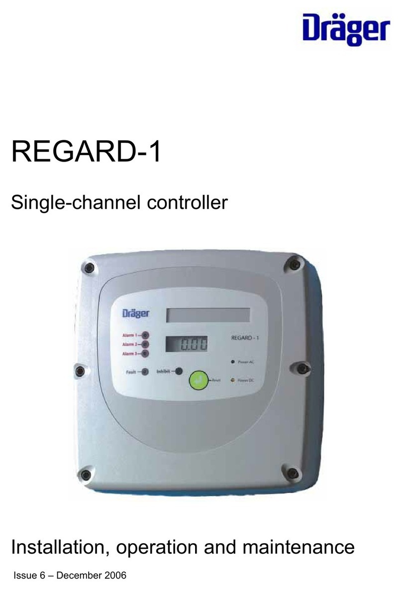
Dräger REGARD-1 Technical Document

Dräger REGARD-1
Single-channel controller
en Installation, operation and maintenance guide


Contents
Issue 5 - June 2005 Page 3 of 64 Pages
Contents
For your safety ..............................................................................................................7
Intended use..................................................................................................................9
CE marking and ATEX approval ..............................................................................................10
Other tests and approvals .........................................................................................................10
Special conditions for safe use according to EC type examination certificate BVS
03 ATEX G 011 X.................................................................................................11
Description...................................................................................................................12
Main circuit board........................................................................................................................13
Field device connecting terminals.....................................................................................................14
24 V battery terminals.........................................................................................................................15
Maintenance inhibit jumper................................................................................................................15
Fuses.....................................................................................................................................................16
Display board...............................................................................................................................16
Display of measuring range, gas and unit.......................................................................................18
Pellistor board......................................................................................................................................18
Options circuit board ..................................................................................................................19
Installation ...................................................................................................................21
Installation environment.............................................................................................................21
Mounting points...........................................................................................................................21
AC supply.....................................................................................................................................22
Connecting transmitters and measuring heads.....................................................................23
Two-wire 4-20 mA transmitter...........................................................................................................23
Three-wire 4-20 mA transmitter ........................................................................................................23

Contents
Issue 5 - June 2005 Page 4 of 64 Pages
Maximum cable resistance for three-wire-transmitters................................................................. 24
Two-wire 4-20 mA transmitter with safety barrier.......................................................................... 25
Polytron SE Ex (Pellistor) measuring head..................................................................................... 26
Relay outputs...............................................................................................................................27
24 V digital outputs for A1 and A2............................................................................................28
Remote reset input......................................................................................................................29
Configuration and calibration.................................................................................... 30
Set measuring range..................................................................................................................30
Calibrating a 4-20 unit................................................................................................................33
Zero calibration ................................................................................................................................... 33
Span calibration .................................................................................................................................. 33
Calibrating an SE Ex unit...........................................................................................................36
Set the sensor current........................................................................................................................ 36
Zero calibration ................................................................................................................................... 38
Calibrate span..................................................................................................................................... 38
Configuring alarms......................................................................................................................39
A1 alarm............................................................................................................................................... 40
A2 alarm............................................................................................................................................... 41
A3 alarm............................................................................................................................................... 41
Fault alarm........................................................................................................................................... 41
Setting alarm thresholds on 4-20 units............................................................................................ 42
Setting alarm thresholds on SE Ex units......................................................................................... 45
Maintenance................................................................................................................ 48
Fault finding..................................................................................................................................48
Specifications.............................................................................................................. 50

Contents
Issue 5 - June 2005 Page 5 of 64 Pages
Part numbers...............................................................................................................52
EC type-examination certificate.................................................................................53
EC Declaration of Conformity ....................................................................................58
Front panel label..........................................................................................................59
Index.............................................................................................................................61


For your safety
Issue 5 - June 2005 Page 7 of 64 Pages
For your safety
NOTE
Observe the instructions for use
Follow the instructions for installation, operation and
maintenance.
maintenance
The device must be inspected and serviced regularly by trained personnel. Keep a
record of inspections and servicing.
Repairs of this device may only be carried out by competent personnel.
We recommend that either a Dräger Safety training course or a DrägerService service
contract be obtained and that all repairs are carried out by DrägerService.
Refer to EN 50073 and/or local regulations.
Concerning transmitter or measuring head operation and maintenance, refer to the
transmitter operating manual or to the measuring head information.
WARNING!
Not for use in areas where explosion hazards are possible
This device is not approved or certified for installation in
potentially explosive atmospheres.
Liability for proper function or damage
Liability for proper function of the device is irrevocably transferred to the owner or
operator to the extent that the equipment is serviced or repaired by personnel not
employed or authorised by DraegerService, or if the equipment is used in a manner not
conforming to its intended use.

For your safety
Issue 5 - June 2005 Page 8 of 64 Pages
Draeger Safety UK Limited can not be held responsible for any damage caused by non-
compliance with the above recommendations. The warranty and liability provisions of
the terms and conditions of sale and delivery of Draeger Safety UK Limited are likewise
not modified by the recommendations given above.
Draeger Safety UK Ltd

Intended use
Issue 5 - June 2005 Page 9 of 64 Pages
Intended use
Regard–1 single-channel controller for 4-20 mA transmitters
•For stationary, continuous monitoring of flammable or toxic gases and vapours,
oxygen deficiency or enrichment.
•Display of measured gas value.
•Indication of alarms and initiation of countermeasures.
•Indication of time-weighted average value, time-weighted average alarm output and
data logger (requires optional RS-232/TWA alarm circuit board).
Regard–1 single-channel controller for SE Ex measuring heads
•For stationary, continuous monitoring of flammable gases and vapours.
•Display of measured gas value.
•Indication of alarms and initiation of countermeasures.
•Indication of time-weighted average value, time-weighted average alarm output and
data logger (requires optional RS-232/TWA alarm circuit board).
The SE Ex device will not work with the Dräger SE Ex LC measuring head.
Both devices are suitable for use in residential, commercial and industrial environments.
The Regard-1 controller is certified according to the directive 94/9/EC (ATEX Directive)
to be operated with performance approved 4-20 mA transmitters (EC-type examination
certificate BVS 03 ATEX G 011X), or with Dräger SE Ex pellistor measuring heads.

Intended use
Issue 5 - June 2005 Page 10 of 64 Pages
CE marking and ATEX approval
Regard-1 is CE marked to indicate conformity to the following directives:
•“ATEX directive” 94/9/EC
•“EMC directive” 89/336/EEC
•“Low-voltage directive” 73/23/EEC
The control unit also bears the following ATEX marking: II (2) G
WARNING!
THIS MARKING DOES NOT MEAN THAT THE UNIT IS “EXPLOSION
PROOF”.
Regard-1 cannot be used in areas subject to explosion hazards
(“hazardous areas”) without suitable protection.
Other tests and approvals
In addition to the measuring function for flammable gases in the range 0 to 100 %LEL
and for oxygen (inertisation) in the range 0 to 25 %(V/V), Regard-1 has been tested
according to DIN EN 45544-1 combined with DIN EN 45544-2 for toxic gases, and
according to DIN EN 50104 for oxygen enrichment and oxygen deficiency, by EXAM
BBG Prüf- und Zertifizier GmbH, Dinnendahlstrasse 9, 44809 Bochum, Germany.
The "Bericht über die Eignungsuntersuchung" has been issued under PFG-No.
41301303.
In Germany only:
NOTE
Read and consider chapter 5 of the "Bericht über die
Eignungsuntersuchung".

Special conditions for safe use according to EC type examination certificate BVS 03
ATEX G 011 X
Issue 5 - June 2005 Page 11 of 64 Pages
Special conditions for safe use according to EC type
examination certificate BVS 03 ATEX G 011 X
Vibration can cause malfunction of alarm and fault check procedures. Do not expose
the device to vibrations with frequencies above 55 Hz or amplitudes above 0.15 mm.
For safety relevant decisions only use the status of the relays. Do not use the display
reading or LED indications. Use a voltmeter between test points TP1 and TP2 for
calibration and adjustment of alarm set points.
Regard-1 4-20:
The alarm relays must be set latching when using transmitters with an output current
which can fall below 20 mA for concentrations above full scale.
Regard-1 SE Ex:
As a minimum, the relay of the main alarm (highest alarm threshold value) must be set
latching.

Description
Issue 5 - June 2005 Page 12 of 64 Pages
Description
The device is available in two versions: 4-20 mA or SE Ex, with or without gas level
display.
An additional “Options circuit board” is available that provides an isolated 4-20 mA
output, TWA alarm relay and data logger with RS-232.
Two 1.2AH lead-acid batteries can be fitted inside the device’s enclosure to provide
continued operation for several hours if AC power is interrupted.
Lead-acid batteries
Display board
Pellistor board
Options circuit board
Main circuit
board
Cable entry area

Description
Issue 5 - June 2005 Page 13 of 64 Pages
Main circuit board
1. Terminals for batteries or external DC input.
2. Connector for display board.
3. Potentiometers for A1 – A3 alarms and display adjustment.
4. Field device connecting terminals.
5. Connector for options circuit board.
1 2 3
4
5
5

Description
Issue 5 - June 2005 Page 14 of 64 Pages
Field device connecting terminals
No. Function
1 2
Reset External reset input
3 4
- 20 mA + 4-20 mA output (requires options circuit board)
5 6
- 24 V + 24 VDC output for safety barrier (100 mA max.)
7 8 9
- Input + 4-20 mA transmitter or SE Ex sensor input
10- 11+
12- 13+ A1 24 V switched output (100 mA max.)
A2 24 V switched output (100 mA max.)
14 15 16
17 18 19 Alarm 1 relay output
Alarm 2 relay output
20 21 22
23 24 25 TWA relay output (requires options circuit board)
A3 relay output
26 27 28
29 30 31 Fault relay output
Inhibit relay output
N E L 98 – 253 VAC output (500 mA max.) (back row terminals)
98 – 253 VAC input (front row terminals)

Description
Issue 5 - June 2005 Page 15 of 64 Pages
24 V battery terminals
For continued operation of the controller when the AC supply fails connect two
12 V/1.2 AH lead-acid batteries in series to the battery terminals. If unsealed batteries
are fitted, that could generate hydrogen when charged, drill a vent hole in the top of the
enclosure.
The 24 V battery terminals can also be used for an external 24 VDC input.
WARNING!
Do not connect AC and DC supplies at the same time.
Maintenance inhibit jumper
When the maintenance inhibit jumper is fitted, all relays will go to their normal state and
all alarms are blocked.
Maintenance

Description
Issue 5 - June 2005 Page 16 of 64 Pages
Fuses
Display board
The display shows the gas level, or indicates that the gas level exceeds the measuring
range (over-range) or is below the measuring range (under-range).
Examples
Normal gas level display.
Negative display reading. A negative display reading
may be caused by inaccurate calibration or by drift or
temperature effect of the sensor.
0.50
- 0.5

Description
Issue 5 - June 2005 Page 17 of 64 Pages
Under-range: Reading below measuring range.
Over-range: reading above measuring range. The
over-range indication is latching and can only be
cleared when the reading is again within the
measuring range. Press Reset to clear the over-range
indication.
There are two versions of the display board:
•V1 displays gas level, under-range and over-range, and calculates a TWA gas level
over eight hours; this board contains firmware release 1.00 or 1.01.
•V2 displays gas level, under-range and over-range and calculates the TWA gas
level over an user-adjustable period, and logs the gas level to memory. this board
contains firmware release 2.00 or 2.01.
The firmware version is shown on the display for a few seconds after the unit is turned
on, and is also marked on the display board.
A buzzer on the display board provides a local audible alarm.
-Ur-
-Or-

Description
Issue 5 - June 2005 Page 18 of 64 Pages
Display of measuring range, gas and unit
The front cover of the controller has a window n which to display the measured gas,
range and unit. A label showing the required information can be inserted in the slot
inside of the front cover. Pre-printed and blank labels are at the end of this manual.
Pellistor board
The pellistor board supplies a constant current to the sensor and amplifies the signal
from the sensor.
To fit the pellistor board to a Regard-1 4-20:
•Remove all the links from SK2 on the main circuit board
•Fit the pellistor board onto SK2
The pellistor board has a four-pole switch and three potentiometers:
•SW1 Sets sensor current range and amplifier range
•VR1 Sets zero point
•VR2 Sets gain (span)
•VR3 Sets sensor current
SW1
VR3
VR1
VR2

Description
Issue 5 - June 2005 Page 19 of 64 Pages
Options circuit board
The options circuit board provides:
•TWA alarm relay (requires display board V2 to operate)
•4-20 mA output proportional to gas level
•datalogger output
Fit the options circuit board onto SK6 and SK9 on the main circuit board.
When the options circuit board is fitted, the 4-20 mA output is on terminals 3 and 4 of
the main circuit board and the TWA relay output is on terminals 20 to 22.
The RS-232 datalogger output is on an RJ11 socket with four conductors.
RS-232
data logger
out
p
ut

Description
Issue 5 - June 2005 Page 20 of 64 Pages
RJ11 socket RS 232 Sub D – 9 Pole
Pin Function Pin Function
1 Rx 3 Tx
2 0 V 5 GND
3 Tx 2 Rx
4 0 V 5 GND
1 NCC
6 NCC
7 RTS
8 CTS
9 NCC
Data are sent by the controller as ASCII characters
Data rate: 2400 Baud
Data bits: 8
Stop bits: 1
Parity: none
Protocol: Xon / Xoff
The gas level is and TWA are printed once every second. Example:
Gas 20.1 TWA 0.1
To reset the TWA value to zero, hold the device’s reset pushbutton pressed for 10s, or
hold the remote reset input closed for 10s, until the display shows tA-0.
Other manuals for REGARD-1
2
Table of contents
Other Dräger Controllers manuals
Popular Controllers manuals by other brands

Danfoss
Danfoss 101N0715 quick start guide

Tews Technologies
Tews Technologies TVME200 Series user manual

Seikom Electronic
Seikom Electronic RLSW5 operating instructions

Snell Advanced Media
Snell Advanced Media 2460 user manual

MKS
MKS 651C instruction manual

Helios
Helios TSD 0,8 Installation and operating instructions