Draper FCR-EPB User manual

INSTRUCTION OVERVIEW FOR
Electronic Parking
Brake Service Tool
Stock No.81276 Part No.FCR-EPB
IMPORTANT: PLEASE READ THESE INSTRUCTIONS CAREFULLY TO ENSURE THE SAFE AND
EFFECTIVE USE OF THIS PRODUCT.
GENERAL INFORMATION
These instructions accompanying the product are the original instructions. This document is part of the product, keep it
for the life of the product passing it on to any subsequent holder of the product. Read all these instructions before
assembling, operating or maintaining this product.
This manual has been compiled by Draper Tools describing the purpose for which the product has been designed, and
contains all the necessary information to ensure its correct and safe use. By following all the general safety instructions
contained in this manual, it will ensure both product and operator safety, together with longer life of the product itself.
AlI photographs and drawings in this manual are supplied by Draper Tools to help illustrate the operation of the product.
Whilst every effort has been made to ensure the accuracy of information contained in this manual, the Draper Tools
policy of continuous improvement determines the right to make modifications without prior warning.

TITLE PAGE
1.1 INTRODUCTION:
USER MANUAL FOR:
ELECTRONIC PARKING BRAKE SERVICE TOOL
Stock no. 81276
Part no. FCR-EPB
1.2 REVISIONS:
As our user manuals are continually updated, users should make sure that they use the very
latest version.
Downloads are available from: http://www.drapertools.com/b2c/b2cmanuals.pgm
DRAPER TOOLS LIMITED WEBSITE: www.drapertools.com
HURSLEY ROAD PRODUCT HELPLINE: +44 (0) 23 8049 4344
CHANDLER’S FORD GENERAL FAX: +44 (0) 23 8026 0784
EASTLEIGH
HAMPSHIRE
SO53 1YF
UK
1.3 UNDERSTANDING THIS MANUALS SAFETY CONTENT:
WARNING! Information that draws attention to the risk of injury or death.
CAUTION! Information that draws attention to the risk of damage to the product or
surroundings.
1.4 COPYRIGHT © NOTICE:
Copyright © Draper Tools Limited.
Permission is granted to reproduce this publication for personal & educational use only.
Commercial copying, redistribution, hiring or lending is prohibited.
No part of this publication may be stored in a retrieval system or transmitted in any other
form or means without written permission from Draper Tools Limited.
In all cases this copyright notice must remain intact.
Date first published July 2015

GUARANTEE
GUARANTEE
Draper tools have been carefully tested and inspected before shipment and are guaranteed
to be free from defective materials and workmanship.
Should the tool develop a fault, please return the complete tool to your nearest distributor
or contact Draper Tools Limited, Chandler's Ford, Eastleigh, Hampshire, SO53 1YF. England.
Telephone Sales Desk: (023) 8049 4333 or Product Helpline (023) 8049 4344.
A proof of purchase must be provided with the tool.
If upon inspection it is found that the fault occurring is due to defective materials or
workmanship, repairs will be carried out free of charge. This guarantee period covering
parts/labour is 12 months from the date of purchase except where tools are hired out when
the guarantee period is ninety days from the date of purchase. The guarantee is extended to
24 months for parts only. This guarantee does not apply to normal wear and tear, nor does it
cover any damage caused by misuse, careless or unsafe handling, alterations, accidents, or
repairs attempted or made by any personnel other than the authorised Draper warranty
repair agent.
Note: If the tool is found not to be within the terms of warranty, repairs and carriage charges
will be quoted and made accordingly.
This guarantee applies in lieu of any other guarantee expressed or implied and variations of
its terms are not authorised.
Your Draper guarantee is not effective unless you can produce upon request a dated receipt
or invoice to verify your proof of purchase within the guarantee period.
Please note that this guarantee is an additional benefit and does not affect your statutory
rights.
Draper Tools Limited.

4
Safety Information
For your own safety and the safety of others, and to prevent damage to the equipment and
vehicles, read this manual thoroughly before operating your EPB service tool. The safety
messages presented below and throughout this user’s manual are reminders to the operator to
exercise extreme care when using this device. Always refer to and follow safety messages and
test procedures provided by vehicle manufacturer. Read, understand and follow all safety
messages and instructions in this manual.
Safety Message Conventions Used
We provide safety messages to help prevent personal injury and equipment damage. Below are
signal words we used to indicate the hazard level in a condition.
Indicates an imminently hazardous situation which, if not avoided, will result in death or serious
injury to the operator or to bystanders.
Indicates a potentially hazardous situation which, if not avoided, could result in death or serious
injury to the operator or to bystanders.
Indicates a potentially hazardous situation which, if not avoided, may result in moderate or minor
injury to the operator or to bystanders.
Important Safety Instructions
And always use your EPB service tool as described in the user’s manual, and follow all safety
messages.
●Do not route the test cable in a manner that would interfere with driving controls.
●Do not exceed voltage limits between inputs specified in this user’s manual.
●Always wear goggles to protect your eyes from propelled objects as well as hot
or caustic liquids.
●Fuel, oil vapors, hot steam, hot toxic exhaust gases, acid, refrigerant and other debris produced
by a malfunction engine can cause serious injury or death. Do not use the EPB service tool in
areas where explosive vapor may collect, such as in below-ground pits, confined areas, or
areas that are less than 18 inches (45 cm) above the floor.
●Do not smoke, strike a match, or cause a spark near the vehicle while testing and keep all
sparks, heated items and open flames away from the battery and fuel / fuel vapors as they are
highly flammable.
●Keep a dry chemical fire extinguisher suitable for gasoline, chemical and electrical fires in work
area.
●Always be aware of rotating parts that move at high speed when an engine is running and keep
a safe distance from these parts as well as other potentially moving objects to avoid serious
injury.
●Do not touch engine components that get very hot when an engine is running to avoid severe
burns.
●Block drive wheels before testing with engine running. Put the transmission in park (for
automatic transmission) or neutral (for manual transmission). And never leave a running engine
unattended.
●Do not wear jewelry or loose fitting clothing when working on engine.

CONTENTS
CONTENTS
Page content Page
INTRODUCTION ................................................................................................................................... 2
GUARANTEE ................................................................................................................................... 3
SAFETY INFORMATION ........................................................................................................................... 4
SAFETY MESSAGE CONVENTIONS USED ......................................................................................... 4
IMPORTANT SAFETY INSTRUCTIONS ............................................................................................... 4
1 USING THIS MANUAL ........................................................................................................................... 7
1.1 BOLD TEXT ................................................................................................................................. 7
1.2 SYMBOLS AND ICONS ................................................................................................................ 7
1.2.1 Solid Spot ........................................................................................................................... 7
1.2.2 Arrow Icon ......................................................................................................................... 7
1.2.3 Note and Important Message ........................................................................................... 7
2 INTRODUCTION ................................................................................................................................... 8
2.1 DESCRIPTIONS ............................................................................................................................ 8
2.2 ACCESSORY DESCRIPTIONS ....................................................................................................... 9
2.3 TECHNICAL SPECIFICATIONS ..................................................................................................... 9
3 GETTING STARTED ............................................................................................................................... 9
3.1 PROVIDING POWER TO EPB SERVICE TOOL ............................................................................. 9
3.1.1 Connecting to Vehicle Power ........................................................................................... 9
3.1.2 Connecting to Personal Computer with USB Cable ....................................................... 10
3.2 APPLICATION OVERVIEW ......................................................................................................... 10
3.3 INPUT DIAGLOG BOX ............................................................................................................... 10
4 DIAGNOSTIC OPERATIONS ................................................................................................................ 11
4.1 VEHICLE IDENTIFICATION ........................................................................................................ 11
4.1.1 Manual Vehicle Selection ................................................................................................ 12
4.1.2 Manual VIN Entry ............................................................................................................ 13
4.2 DIAGNOSTIC FUNCTION SELECTION ...................................................................................... 13
4.2.1 Read Codes ....................................................................................................................... 14
4.2.2 Erase Codes ...................................................................................................................... 15
4.2.3 Live Data .......................................................................................................................... 16
4.2.3.1 Complete Data List ................................................................................................. 16
4.2.3.2 Custom Data List ..................................................................................................... 19
4.2.4 ECU Information .............................................................................................................. 20
4.2.5 Special Function ............................................................................................................... 21
5 OBDII/EOBD OPERATIONS ................................................................................................................. 22
5.1 SYSTEM STATUS ....................................................................................................................... 23
5.2 READ CODES ............................................................................................................................ 24
5.3 ERASE CODES ........................................................................................................................... 26
5.4 LIVE DATA ................................................................................................................................ 26
5.4.1 Complete Data List .......................................................................................................... 27
5.4.2 Custom Data List .............................................................................................................. 29
5.5 FREEZE FRAME ......................................................................................................................... 30
5.6 READ I/M READINESS STATUS DATA ...................................................................................... 31
5.7 O2 MONITOR TEST ................................................................................................................... 33
5.8 ON-BOARD MONITOR TEST ..................................................................................................... 34
5.9 COMPONENT TEST ................................................................................................................... 36
5.10 REQUEST VEHICLE INFORMATION ........................................................................................ 37

CONTENTS
5.11 MODULES PRESENT ................................................................................................................ 39
5.12 DTC LOOKUP .......................................................................................................................... 40
6 PLAYBACK DATA ................................................................................................................................ 41
7 SYSTEM SETUP ................................................................................................................................. 43
7.1 SELECT LANGUAGE .................................................................................................................. 43
7.2 CHANGE UNITS ......................................................................................................................... 44
7.3 CONFIGURE BEEPER ................................................................................................................. 45
7.4 TEST KEYPAD ............................................................................................................................ 45
7.5 LCD KEYPAD ............................................................................................................................. 46
7.6 TOOL INFORMATION ............................................................................................................... 46
7.7 CONFIGURE SHORTCUT KEYS .................................................................................................. 47
Note: Draper Tools accepts no responsibility for any accident or
injury arising from servicing the vehicles system. When
interpreting results from the vehicle, always follow the
manufacturer’s recommendation for repair.
Page content Page

7
1 Using This Manual
We provide tool usage instructions in this manual. Below are the conventions we used in the
manual.
1.1 Bold Text
Bold text is used to highlight selectable items such as buttons and menu options.
Example:
Press the ENTER button to select.
1.2 Symbols and Icons
1.2.1 Solid Spot
Operation tips and lists that apply to specific tool are introduced by a solid spot ●.
Example:
When System Setup is selected, a menu that lists all available options displays. Menu options
include:
●Languages
●Unit
●Beep
●Keypad Test
●LCD Test
●About
●Shortcuts
1.2.2 Arrow Icon
An arrow icon indicates a procedure.
Example:
To change menu language:
1. Scroll with the arrow keys to highlight Language on the menu.
2.Press the ENTER button to select.
1.2.3 Note and Important Message
Note
A NOTE provides helpful information such as additional explanations, tips, and comments.
Example:
NOTE
Test results do not necessarily indicate a faulty component or system.
Important
IMPORTANT indicates a situation which, if not avoided, may result in damage to the test
equipment or vehicle.
Example:
IMPORTANT
Do not soak keypad as water might find its way into the EPB service tool.
8
2 Introduction
The new Electronic Park Brake Service Tool is specially designed to allow the service and
maintenance of brake systems on multiple brands of vehicles where electronic brake systems are
fitted.
With the tool properly connected to the vehicle’s data link connector (DLC), you can use the EPB
service tool to read diagnostic trouble codes and view “live” data readings from EPB control
systems. You can also save “recordings” of the data readings.
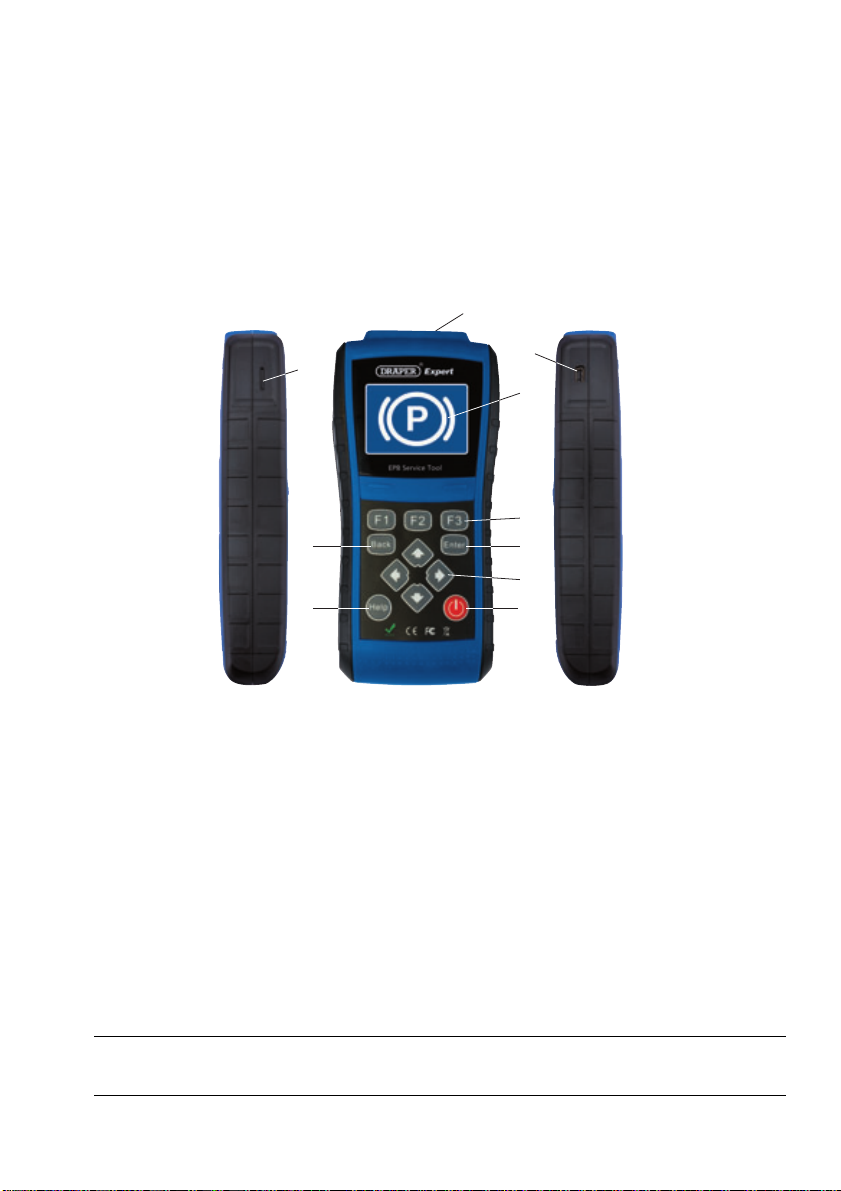
2.1 Descriptions
This section illustrates external features, ports and connectors of the tool.
Figure 2-1 Front View
1 Diagnostic Port - provides connection between the EPB service tool and vehicle.
2 LCD Display - shows menus, test results and operation tips.
3 Function Keys / Shortcut keys - three keys that correspond with “buttons” on some screens
for executing special commands or provide quick access to most frequently used applications
or functions.
4 ENTER Key - executes a selected option and generally goes to the next screen.
5 Direction Keys - select an option or scroll through a screen of data or text.
6 Power Switch - turns on/off the EPB service tool and press and hold for 5 seconds for
emergency reboots.
7 HELP Key - displays helpful information.
8 BACK Key - exits a screen and generally returns to previous screen.
9 TF Card Port - holds the TF memory card for data backup and software update.
10 USB Port - provides a USB connection between the EPB service tool and PC or laptop.
IMPORTANT
Do not use solvents such as alcohol to clean keypad or display. Use a mild nonabrasive detergent
and a soft cotton cloth.

9
2.2 Accessory Descriptions
This section lists the accessories that go with the EPB service tool. If you find any of the following
items missing from your package, contact your local dealer for assistance.
1 User’s Guide - provides operation instructions for the usage of the EPB service tool.
2 USB Cable - provides connection between the EPB service tool and a computer to upgrade the
tool.
3 TF Memory Card - contains the EPB service tool’s operating software and applications.
IMPORTANT
Do not remove the memory card unless performing updates to the card.
4 Diagnostic Cable - provides connection between the EPB service tool and vehicle.
5 Nylon Carry Pouch - stores the EPB service tool and its accessories.
2.3 Technical Specifications
Display: Backlit, 480*272 TFT color display
Working Temperature: 0 to 60 (32 to 140)
Storage Temperature: -20 to 70(-4 to 158)
Power Supply: 8-18V vehicle power, 12V AC/DC power, 3.3V USB power
Dimensions (L*W*H): 200*130*40mm
Gross Weight: 1.2Kg
Protocols: SAE J1850 (VPW and PWM), ISO 9141-2, ISO 14230-2 (KWP 2000), ISO 15765-4
(CAN)
3 Getting Started
This section describes how to provide power to the EPB service tool, provides brief introductions
of applications loaded on the EPB service tool and display screen layout and illustrates how to
input text and numbers with the EPB service tool.
3.1 Providing Power to EPB Service Tool
Before using the EPB service tool, make sure to provide power to the EPB service tool.
The unit operates on any of the following sources:
●12-volt vehicle power
●USB connection to personal computer
3.1.1 Connecting to Vehicle Power
The EPB service tool normally powers on whenever it is connected to the data link connector
(DLC).
To connect to vehicle power:
1. Locate the data link connector (DLC). The DLC is generally located under the dash on the
driver side of the vehicle.
2. Attached the diagnostic cable to the EPB service tool and tighten the captive screws to ensure
good connection.
3. Connect a correct adapter to the data cable according to the vehicle being serviced and plug it
into the vehicle DLC.
4. Switch the ignition key to the ON position.
5. The EPB service tool automatically boots up.
10
IMPORTANT
Never try to provide power for the EPB service tool from USB connection when the EPB service
tool is communicating with a vehicle.
3.1.2 Connecting to Personal Computer with USB Cable
The EPB service tool also receives power through the USB port when it is connected to a PC for
updating software and transferring saved files.
To connect to PC:
1. Insert the small end of the USB cable to the USB port at the right side of the EPB service tool
and the large end to a computer.
2. Press the power switch of the EPB service tool to power it on.
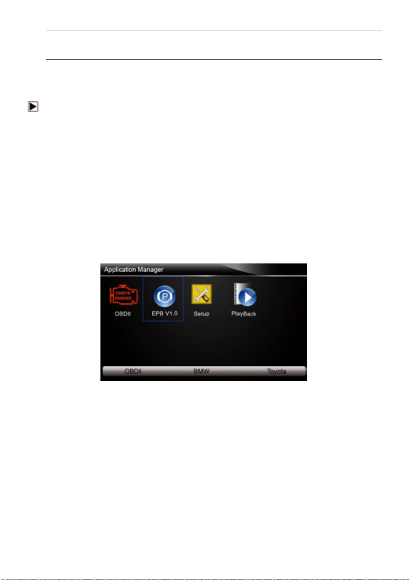
3.2 Application Overview
When the EPB service tool boots up, the home screen opens. This screen shows all applications
loaded on the unit.
Following applications are preloaded into the EPB service tool:
●OBDII/EOBD – leads to OBDII screens for all 9 generic OBD system tests.
●EPB – leads to screens for diagnostic trouble code information, live datastream, ECU
information, special functions of electric parking brake systems on 13 vehicle makes sold
worldwide.
●Setup – leads to screens for adjusting default settings to meet your own preference and view
information about the EPB service tool.
●Playback – leads to screens for access saved data files.
Figure 3-1 Sample Home Screen
3.3 Input Dialog Box
This section illustrates how to use the tool to input letters and numbers, such as VIN number,
channel number, test values and DTC number. Typically, you may be required to input letters or
numbers when you are doing any of the following operations.
●VIN entry
●input channel number
●set adaptation value
●look up DTCs
The tool provides 4 different types of keyboard to meet your specific needs. Depending on the
needs of text entry, it automatically shows the most suitable keypad.
●classic QWERTY keyboad for input of texts that contain both letters and numbers
●numeric keyboard for input of numbers
11
●alphabet keyboard for input of letters
●hexadecimal keyboard for special functions.
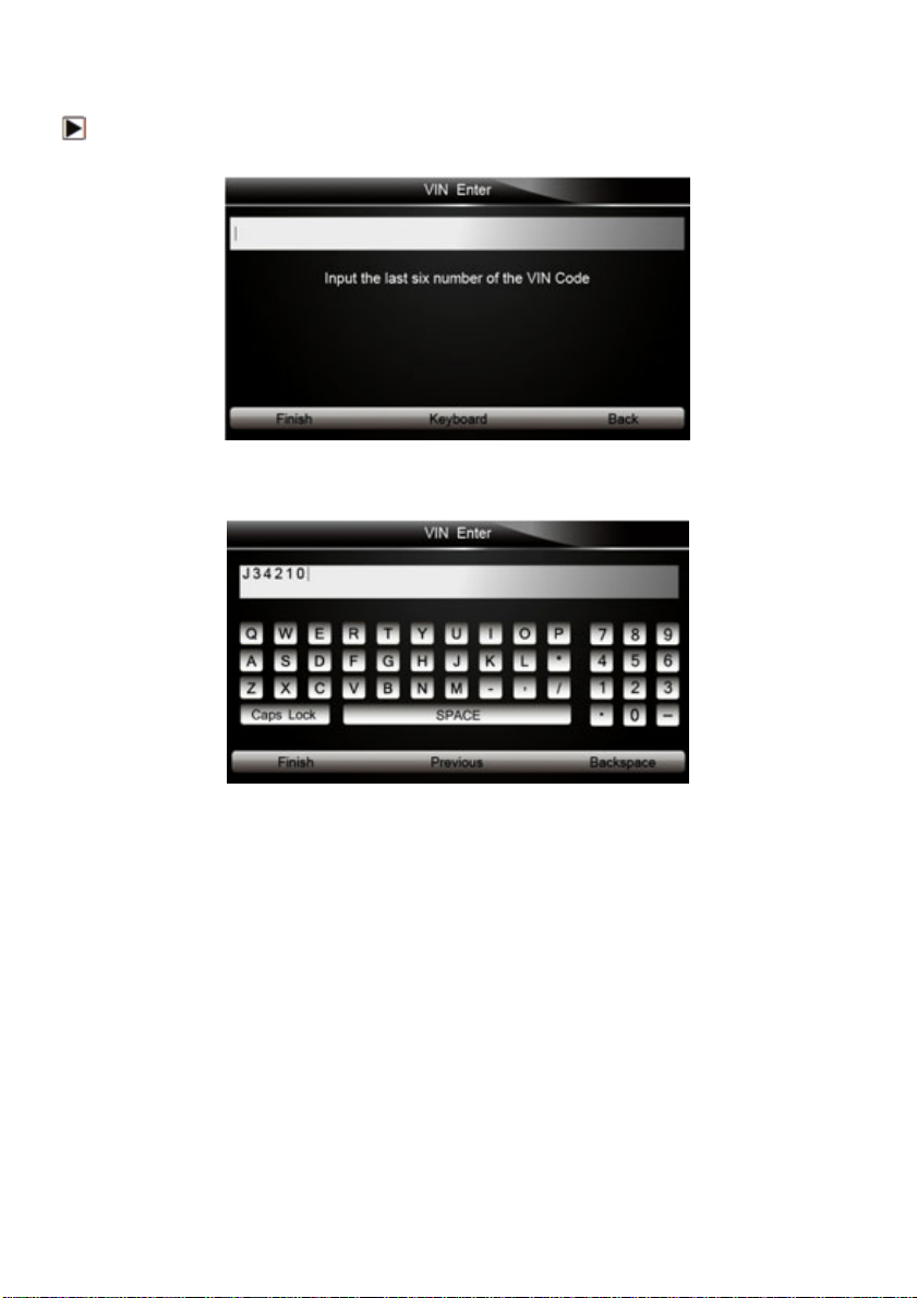
To input text with the EPB service tool:
1. When you are requested to input text, press the function key Keyboard, and the keyboard
displays.
Figure 3-2 Sample Input Text Screen
2. Scroll with the arrow keys to highlight your desired letter or number and press the ENTER key
to confirm.
Figure 3-3 Sample Numeric Keyboard Screen
3. To delete a letter or number, use the function key Previous to move the cursor to it and then
press the Backspace button.
4. When finished the entry, press Finish key to continue.
4 Diagnostic Operations
This section illustrates how to use the EPB service tool to read and clear diagnostic trouble codes,
and view “live” data readings and ECU information on Electronic Parking Brake systems of 13
vehicles and also save “recordings” of the data readings.
4.1 Vehicle Identification
The vehicle identification information presented is provided by the ECM of the vehicle being
tested. Therefore, certain attributes of the test vehicle must be entered into the tool to ensure the
data displays correctly. The vehicle identification sequence is menu driven, you simply follow the
screen prompts and make a series of choices. Each selection you make advances you to the next
screen. Exact procedures may vary somewhat by vehicle.
It typically identifies a vehicle by the following methods.
12
●Manual vehicle selection
●Manual VIN entry
NOTE
Not all identification procedure listed below is applicable to all vehicles. Available options may
vary by vehicle manufacturer.
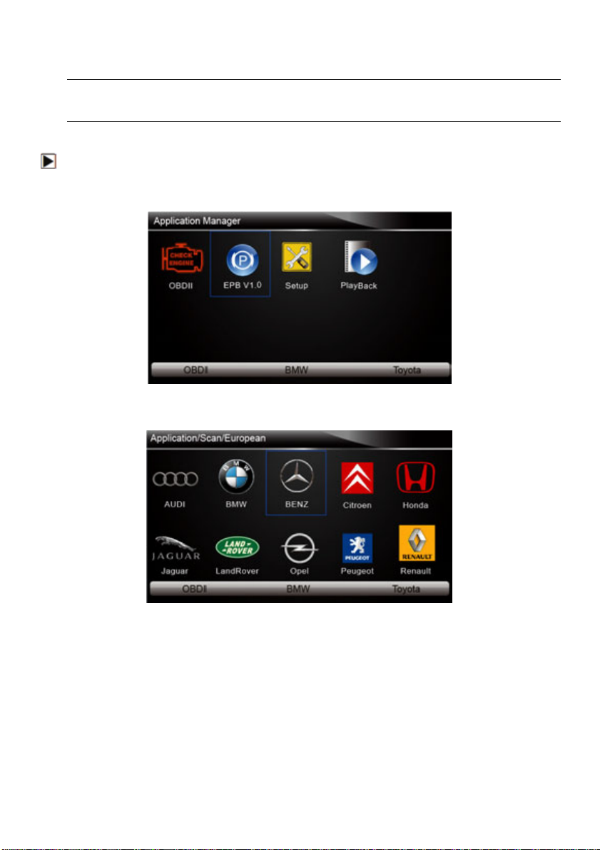
4.1.1 Manual Vehicle Selection
To identify a vehicle by manual vehicle selection:
1. Scroll with the arrow keys to highlight EPB from the Application menu and press the ENTER
key to start. If you have the application assigned to one of the function keys at the bottom of the
screen, you can alternatively press the function key to start the application.
Figure 4-1 Sample Application Menu
2. A screen with vehicle manufacturer displays. Select the vehicle manufacturer being tested.
Figure 4-2 Sample Vehicle Manufacturer Selection Screen
3. On each screen that appears, select the correct option and then press the ENTER key. Do this
until the complete vehicle information is entered and the diagnostic menu displays.

13
Figure 4-3 Sample Vehicle Selection Screen
4.1.2 Manual VIN Entry
Manual VIN Entry identifies a vehicle by manually inputting a 17-digit VIN code.
To identify a vehicle by manual VIN entry:
1. Refer to Step 1-2 of 4.1.1 manual vehicle selection.
2. A virtual keyboard opens for VIN entry. Input a valid VIN code as required on screen and use
the function key Finish to confirm. The tool starts to identify the vehicle.
Figure 4-4 Sample Manual VIN Entry with Keyboard
4.2 Diagnostic Function Selection
This section illustrates how to work on the electronic parking brake systems.
To perform diagnosis:
1. Turn the ignition off.
2. Release the park brake and make sure the car is properly blocked.
3. Locate the vehicle’16-pin Data Link Connector (DLC)
4. Plug into the diagnostic cable to the vehicle’s DLC.
5. Turn the ignition on.
6. Scroll with the arrow keys to highlight EPB from Home screen and press the ENTER key.
7. After you have completed the identification of vehicle and the EPB service tool establishes
communication with the vehicle, the Diagnostic Menu displays.
The menu options may include:
●Read Codes
14
●Erase Codes
●Live Data
●ECU Information
●Special Function
NOTE
Not all function options listed above are applicable to all vehicles. Available options may vary by
the year, model, and make of the test vehicle. A “The selected mode is not supported!” message
displays if the option is not applicable to the vehicle under test.
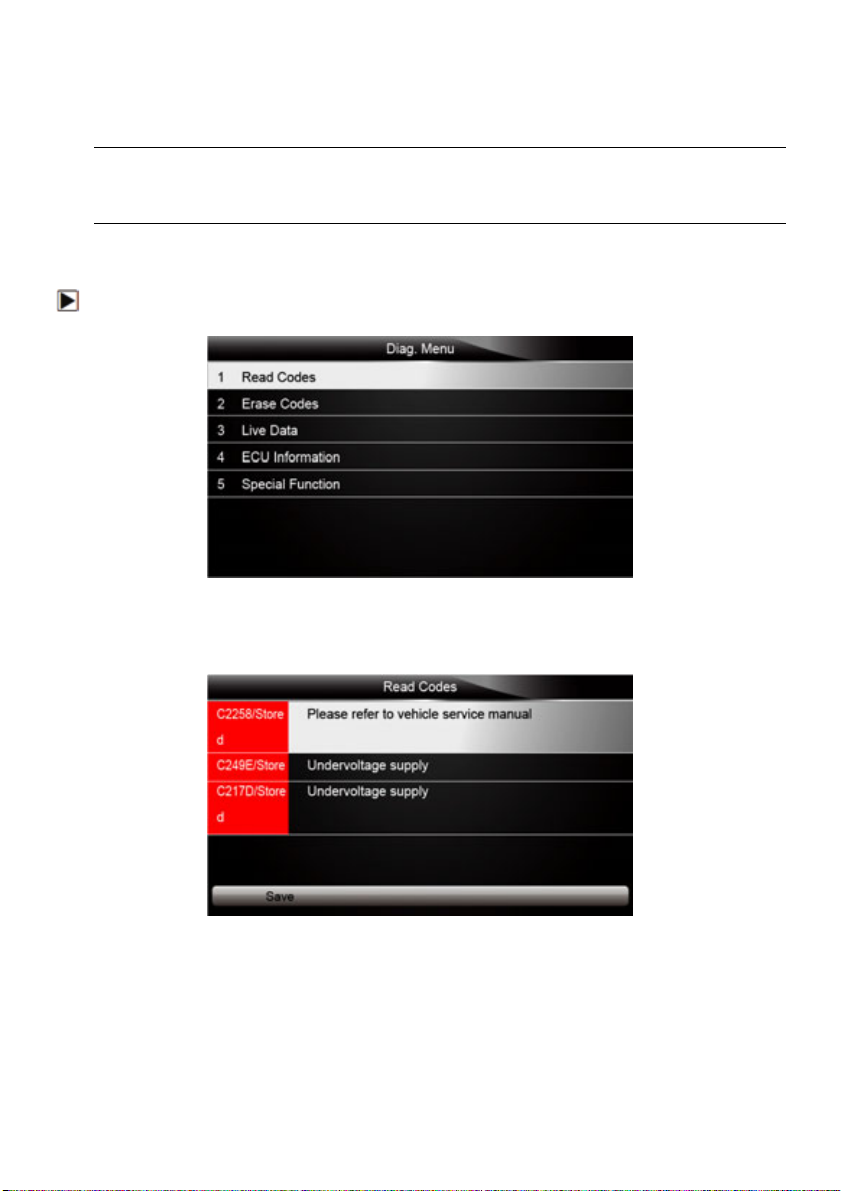
4.2.1 Read Codes
Read Codes menu lets you read trouble codes found in the control unit.
To read codes from a vehicle:
1. Scroll with the arrow keys to highlight Read Codes from Diag. Menu and press the ENTER key.
Figure 4-5 Sample Function Menu Screen
2. A code list including code number and its description displays. Use the up and down arrow keys
to scroll through data to select lines, and left and right arrow keys to scroll back and forth
through different screens of data.
Figure 4-6 Sample Code Screen
3. Press function key Save to store DTC information. Or use the BACK key to exit.
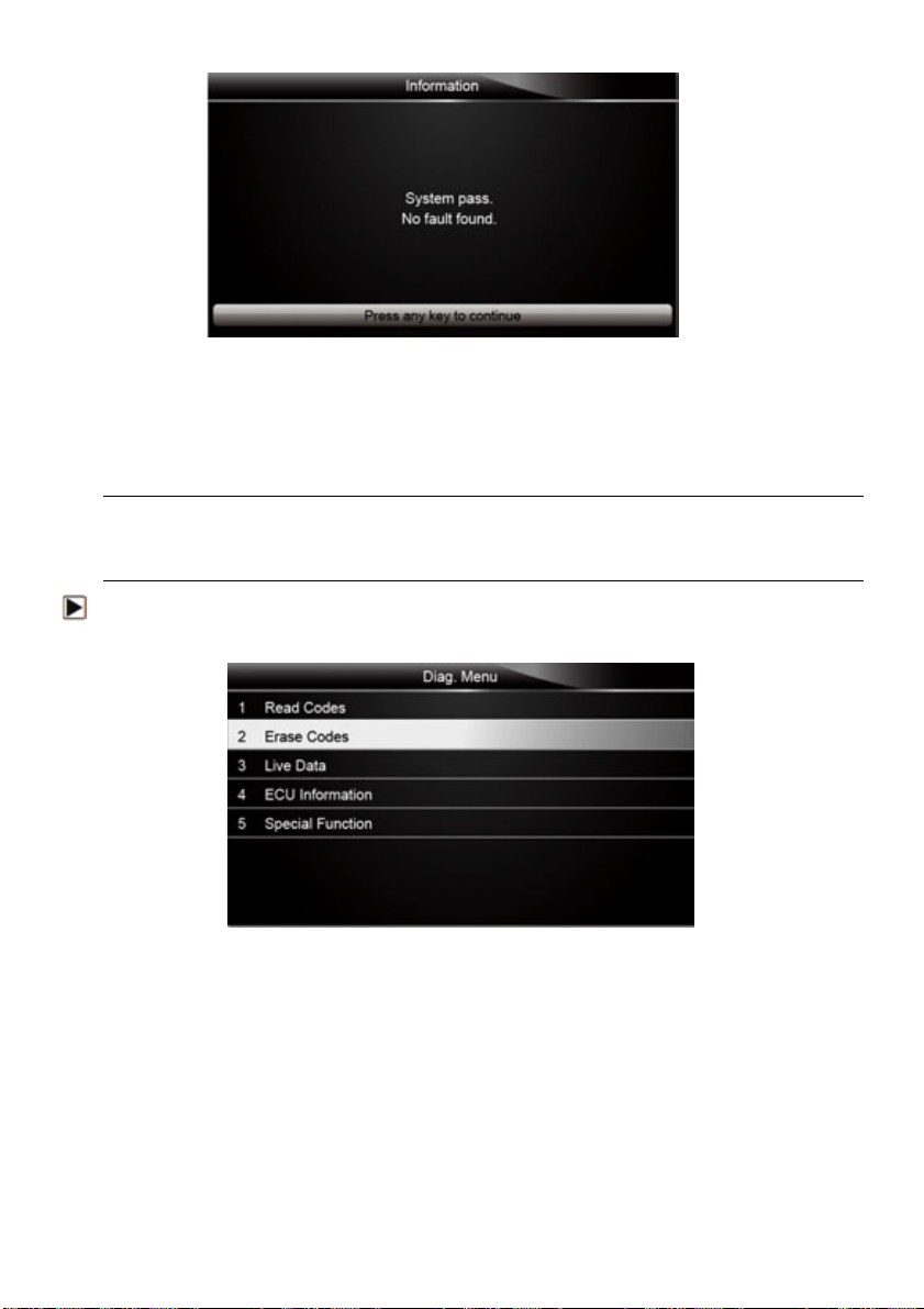
3. If there is no trouble code, the following screen displays. Press any key to return to the function
menu.
15
Figure 4-7 Sample No Fault Screen
4.2.2 Erase Codes
Erase Codes menu lets you to clear all current and stored DTCs from the control module. Also it
erases all temporary ECU information, so make sure that the selected system are completely
checked and serviced by technicians and no vital information will be lost before clearing codes.
NOTE
●To clear codes, make sure that the ignition key is switched to ON with the engine off.
●Erase Codes does not fix the problem that caused the fault! DTCs should only be erased after
correcting the condition(s) that caused them.
To clear codes:
1. Scroll with the arrow keys to highlight Erase Codes from Diag. Menu and press the ENTER
key.
Figure 4-8 Sample Function Menu Screen
16
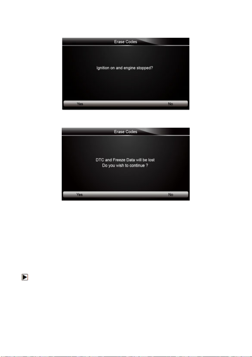
2. Follow the on-screen instructions and answer questions about the vehicle being tested to enter
into next screen.
Figure 4-9 Sample Erase Codes Screen 1
3. Press the function key Yes to complete the procedure.
Figure 4-10 Sample Erase Codes Screen 2
3. Check the codes again. If any codes remain, repeat the Erase Codes steps.
4.2.3 Live Data
Live Data menu lets you view and record real time PID data from EPB system.
Menu options typically include:
●All Data List
●Custom Data List
4.2.3.1 All Data List
ALL Data List menu lets you view all live PID data from EPB system.
To view all live PID data
17
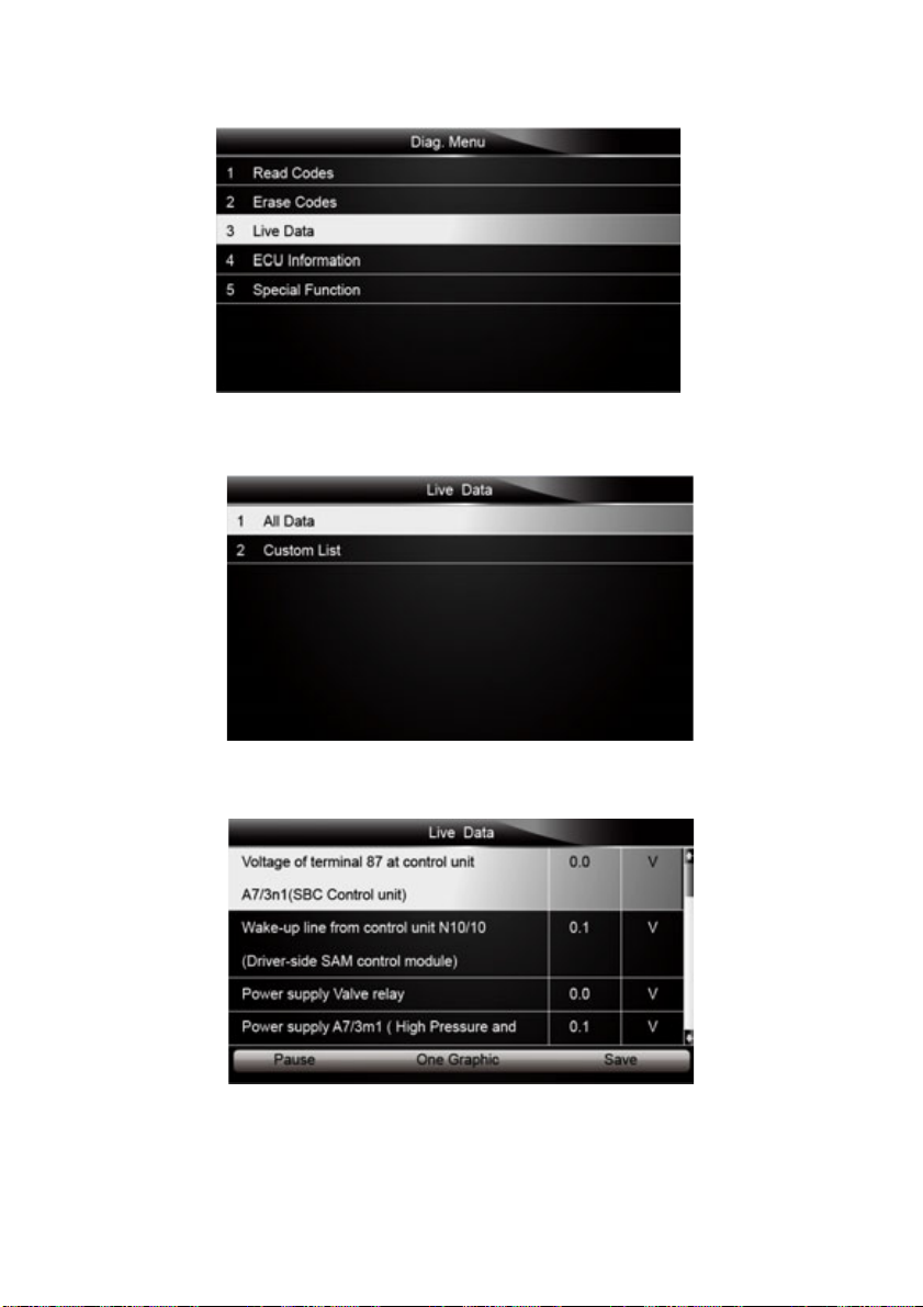
1. Scroll with the arrow keys to highlight Live Data from the menu.
Figure 4-11 Sample Diag. Menu Screen
2. Press the ENTER key to display the live data menu.
Figure 4-12 Sample Live Data Selection Screen
3. Select the All Data from the menu and press the ENTER key to display the datastream screen.
Figure 4-13 Sample All Data Screen
4. Scroll with the up and down arrow keys to highlight a line, if the One Graphic on the bottom is
highlighted, it indicates the graphing is available for the selected line. Press the function key
One Graphic to display the PID graph.

18
Figure 4-14 Sample PID graph Screen
5. Press the function key Two Graphics to display two PID graphs in one screen.
Figure 4-15 Sample Two PID Graph Screen
6. Press the function key Merge Graph to display two PID plots in one coordinate for easy and
intuitive diagnosis.
Figure 4-16 Sample Merged PID Plots Screen
7. To record the data to memory of the EPB service tool, use the function key SAVE, and press
Stop Saving to stop recording at any time.
8. Press Text to return to text viewing of PID data.
9. Select Pause to suspend collecting data from the EPB service tool and use the Continue key
to resume collecting data.
10.Press the Back key to return to the previous menu.

19
4.2.3.2 Custom Data List
Custom Data List menu lets you to minimize the number of PIDs on the data list and focus on any
suspicious or symptom-specific data parameters.
To create a custom data list:
1. Select Custom List from the menu and press the ENTER key.
Figure 4-17 Sample Live Data Screen
2. The custom datastream selection screen displays. Scroll with the up and down arrow keys to
highlight a line, press the ENTER key and then repeat the action to make more selections.
Figure 4-18 Sample Custom List Selection Screen
NOTE
To deselect an item, select it again and then press the ENTER key. Alternatively, use the function
keys SELECT ALL and CLEAR ALL to select or deselect all items at once.

20
3. When finished selection, use the function key VIEW DATA to display selected items.
Figure 4-19 Sample Datastream Screen
4.2.4 ECU Information
ECU Information screen displays the identification data of the control module under test, such as
the control module identification string and the control module coding.
To read ECU information:
1. Select ECU Information from Diag. menu and press the ENTER key.
Figure 4-20 Sample Function Menu Screen
2. A screen with detailed information of the selected control module displays.
Figure 4-21 Sample ECU Information Screen
This manual suits for next models
1
Table of contents
Popular Service Equipment manuals by other brands

Tektino
Tektino RCC-9A Maintenance manual

Selecta
Selecta DIESELPAK 300 instruction manual

FLO-DYNAMICS
FLO-DYNAMICS RADCVAC3 manual

Glentronics
Glentronics PRO Series instruction manual

HENNESSY INDUSTRIES
HENNESSY INDUSTRIES Coats H.I.T. 5000H2 instruction manual

Hedson
Hedson IRT-UVA 1 PrepCure 3 Digital Assembly, Operation and Spares Manual


