manuals.online logo
Brands
  1. Home
  2. •
  3. Brands
  4. •
  5. Drayton
  6. •
  7. Temperature Controllers
  8. •
  9. Drayton Lifestyle LP111Si Operating instructions

Drayton Lifestyle LP111Si Operating instructions

INTRODUCTION
In cases where a forced ‘service interval’ is required, a
service warning feature can be selected and programmed
by the installer only. This feature will reduce the comfort
level of the dwelling by a cycling controlled method,
The heating will run only for the first 15 mins of each hour
during the programmed time
The hot water will run only for the first 13 mins of each hour
during the programmed time.
FUNCTION
The required ‘service’ date must be set, by entering the
‘number of days’ from now to when the next service is
due and the alarm must be selected (if required)
30 days before the total ‘number of days’ have elapsed
the following warning will be shown on the display of the
programmer,
SERVICE, then...
DUE, then...
DUAL
CHANNEL
SINGLE
CHANNEL
SERVICE INTERVAL INSTRUCTIONS
For use with
for heating OR hot water
LP111Si, LP711Si LP241Si, LP522Si, LP722Si
for heating AND hot water
FOR THE INSTALLER/SERVICE ENGINEER ONLY!
DO NOT LEAVE WITH END USER!
SINGLE
CHANNEL
Timeswitch
DUAL
CHANNEL
Programmer
SERVICE INTERVAL
Lifestyle
FUNCTION Cont...
25th DEC, then...
Todays time
The backlight will flash to draw attention!
This sequence will cycle continuously for 30 days until the preset
‘service date’ (‘number of days’) is reached.
When the ‘service date’ (‘number of days’) is reached the
display will show
SERVICE
Both the LCD and backlight will flash to draw attention!
The programmer will be functioning in the ‘reduced comfort’
mode as described earlier
All normal programmer functions will be disabled
An audible alarm will sound
The alarm can be put into ‘snooze’
for 24hrs by pressing any button
The programmer can only be returned to normal operation
by re-setting with the ‘LPSi – Reset Unit’
INSTALLER/SERVICE ENGINEER INSTRUCTIONS
Setting the Service Interval Features
NOTE: ENSURE THE TIME & DATE ARE SET CORRECTLY BEFORE
SETTING/CONFIRMING THE SERVICE INTERVAL SETTINGS
To access the menu, on the LPxxxSi unit, for the service interval
feature press the ‘-‘ (minus) button for longer than 8 (eight)
seconds and the display should show,
If the programmer is in the Service mode, i.e.SEr permanently
displayed then you will have to reset the programmer by
positioning the reset unit as shown below and pressing the
button before the service interval menu can be accessed.
Press the ‘+’ (plus) button to switch the ‘service interval’
feature on or off.
Press the SET? Button to confirm this setting. The display
should now show,
Press the ‘+’ (plus) button to switch the ‘audible alarm feature
on or off. The alarm will sound after the 30 day warning period
is complete and the service is due
CHANGING THE BATTERY (Reset Unit)
Remove the screw on the bottom of the unit and take off
the back cover. This gives access to the replaceable battery
(type: CR2032 lithium cell).
Please dispose of the used battery carefully.
INSTALLER/SERVICE ENGINEER INSTRUCTIONS Cont...
Press the SET? Button to confirm this setting. The display
should now show,
e.g.
Press the ‘+’ (plus) or ‘-‘ (minus) buttons to set the required
service interval in days.
Press the SET? Button to confirm this setting. The display
should now show,
Con (confirm) will flash for 2 minutes
You now have 2 mins to send the ‘Reset’ signal using the handheld
LPSi reset unit from Drayton.
Position the reset unit 0-2.5 cm (0-1") away from the
programmers display, the reset unit should be central to
the display (see diagram below)
Press the raised button once, the programmers counter will
now be reset and the display should now show,
The Con should not flash.
This will remain for approx 10 seconds, and then the programmer
will return to normal function, and the service settings will be set.
i.e.
It will not be in the ‘Si’ special menu.
If the programmer has not received the reset signal within the
2 mins the programmer will return to the normal function but
the new settings will not be stored. You will have to start the
programming sequence again.
0 - 2.5cm
Service Interval Reset Unit
FOR THE INSTALLER/SERVICE ENGINEER ONLY!
DO NOT LEAVE WITH END USER!
Climate Controls Europe
Sales: 0845 1305522 / Technical Helpline: 0845 1307722
Email: customer[email protected] / Web: www.draytoncontrols.co.uk
06515016001 ISS.C.
INSTALLERS/ENGINEERS NOTES

Other manuals for Lifestyle LP111Si

3

This manual suits for next models

4

Other Drayton Temperature Controllers manuals

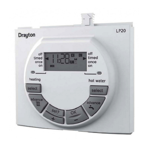
Drayton LP20 Operation manual

Drayton

Drayton LP20 Operation manual

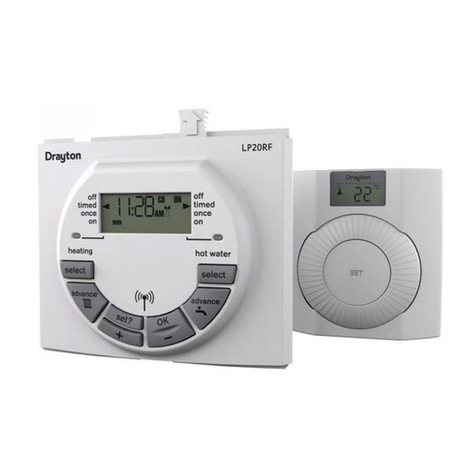
Drayton LP20RF Operation manual

Drayton

Drayton LP20RF Operation manual

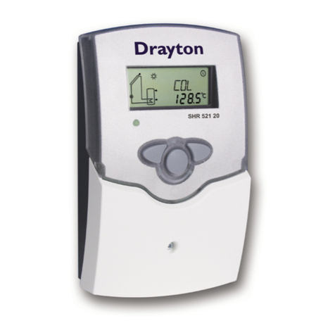
Drayton SHR 521 20 User manual

Drayton

Drayton SHR 521 20 User manual

Popular Temperature Controllers manuals by other brands

SUNWARD SUN-15T user manual

SUNWARD

SUNWARD SUN-15T user manual

Avtech RMA-DET-SEN Installation notes

Avtech

Avtech RMA-DET-SEN Installation notes

Gira 2370 operating instructions

Gira

Gira 2370 operating instructions

Omron C200H-TV Series Operation manual

Omron

Omron C200H-TV Series Operation manual

Auber Instruments WSD-1510GPH quick guide

Auber Instruments

Auber Instruments WSD-1510GPH quick guide

Fuji Electric Micro-Controller X Socket type Operation manual

Fuji Electric

Fuji Electric Micro-Controller X Socket type Operation manual

RedWave Labs LTC25 operating manual

RedWave Labs

RedWave Labs LTC25 operating manual

Temperature@lert TM-WIFI220 user guide

Temperature@lert

Temperature@lert TM-WIFI220 user guide

Siemens SITRANS TS Series operating instructions

Siemens

Siemens SITRANS TS Series operating instructions

dixell Wing XW270L Installation and operating instructions

dixell

dixell Wing XW270L Installation and operating instructions

merten 6232 Series operating instructions

merten

merten 6232 Series operating instructions

Newport 3150 user manual

Newport

Newport 3150 user manual

Future Design FDC-9090 user manual

Future Design

Future Design FDC-9090 user manual

Heat Controller B-VCH12FC-1 owner's manual

Heat Controller

Heat Controller B-VCH12FC-1 owner's manual

Aprilaire 8051 installation instructions

Aprilaire

Aprilaire 8051 installation instructions

THORLABS TED4015 Operation manual

THORLABS

THORLABS TED4015 Operation manual

Siemens QMX3.P37 Technical principles

Siemens

Siemens QMX3.P37 Technical principles

Auber Instruments WSD-1500H-W Operation & instruction manual

Auber Instruments

Auber Instruments WSD-1500H-W Operation & instruction manual

manuals.online logo
manuals.online logoBrands
  • About & Mission
  • Contact us
  • Privacy Policy
  • Terms and Conditions

Copyright 2025 Manuals.Online. All Rights Reserved.