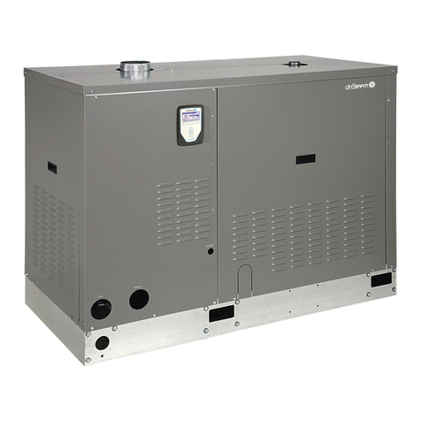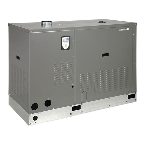
6DRISTEEM GTS HUMIDIFIER INSTALLATION AND OPERATION MANUAL
Supply water piping
TAP/SOFTENED WATER
The primary component of the supply water assembly is a solenoid valve,
which may cause noise during fill cycles.
During a fill cycle, cold supply water drops the internal tank temperature and
may collapse the boil, which can cause a low rolling sound. To minimize this,
use hot supply water.
In cases where water hammer occurs when the fill solenoid closes, a shock
arrester is recommended. Reducing the supply water pressure (minimum
172 kPa with fill valve open) or using flexible tubing (rated for 100 °C
minimum continuous operating temperature) may diminish the noise.
The minimum water conductivity for the GTS tap/softened water model
is 30 µS/cm.
RO/DI WATER OPTION
The water level in GTS humidifiers with the RO/DI water option is controlled
with a float valve. For models with the end-of-season drain option, a solenoid
valve is installed prior to the float valve.
When using nonmetallic tubing, DriSteem recommends the installer place a
50-mm water seal/loop in the supply water line to isolate steam during RO/DI
water system maintenance.
DriSteem highly recommends installing a strainer in the supply water line
to prevent clogging of the solenoid valve or float valve orifice. The strainer
prevents particulate from collecting at the solenoid valve seat.
To minimize RO/DI water waste, disconnect factory piping to the water
tempering device and pipe directly to a tap water source.
WARNING
Fire hazard if using tap/softened supply water with RO/DI water option:
If a GTS humidifier with the RO/DI water option is supplied with
tap/softened fill water, the float valve assembly will become clogged,
and particulate will accumulate on the low water cutoff switch (float
switch). This will cause failure of a critical safety circuit and the potential
for a dry tank fire, which can cause severe property damage, severe
personal injury, or death.
SUPPLY WATER FLOW RATES
The rate of supply water flow into the GTS humidifier tank is determined by the
supply water pressure and the inlet valve. See Table 6-2.
mc_071912_1545
SUPPLY WATER GUIDELINES
Supply water quality is an important
component of humidifier reliability and
maintenance.
Examples:
• Corrosive water can decrease the
service life of the humidifier.
• Excessive water hardness can
increase the humidifier maintenance
requirements.
To maximize humidifier service life
and minimize humidifier maintenance,
DriSteem has established guidelines for
supply water See Table 6-1.
Table 6-1:
DriSteem supply water guidelines
Chlorides*
RO or DI water
Softened water
Tap water
* Damage caused by
chloride corrosion is
not covered by your
DriSteem warranty.
< 5 ppm
< 25 ppm
< 50 ppm
Total hardness
Tap water < 500 ppm
pH
RO, DI, or softened
water
Tap water
7 to 8
6.5 to 8.5
Silica < 15 ppm
You may wish to take action to mitigate
potential negative effects to your
humidifier. Supply water outside of these
guidelines may void your DriSteem
warranty. Please contact your DriSteem
distributor if you need advice.
Table 6-2:
Supply water flow rates (liters per minute)
Supply
water
pressure
Solenoid valve flow rates
(tap/softened water)
Float valve flow rates (RO/DI water)
Models 100 – 400 Models 500 – 800
200 kPa 7.2 6.7 17.0
350 kPa 9.0 8.8 22.5
450 kPa 10.2 9.9 25.4
550 kPa 11.1 10.8 27.6
