Droplet SP2-XR User manual

Operator Manual
2400 Trade Centre Avenue
Longmont, CO 80503 USA
DOC-0425 Revision A
A L L R I G H T S R E S E R V E D
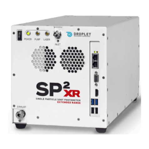
SP2XR
Single Particle Soot Photometer
Extended Range

DOC-0425 Rev A
© 2018 DROPLET MEASUREMENT TECHNOLOGIES LLC
2
C O N T E N T S
Specifications.................................................................................................... 5
1.1 General Specifications........................................................................................................... 5
1.2 Electrical Specifications......................................................................................................... 6
1.3 Physical Specifications........................................................................................................... 6
1.4 Operating Limits.................................................................................................................... 6
General Information.......................................................................................... 7
2.1 Safety Information ................................................................................................................ 8
2.2 Interface Features ................................................................................................................. 9
Introduction...................................................................................................... 9
Unpacking and Setup .......................................................................................10
4.1 Unpacking............................................................................................................................ 10
4.2 Set Up.................................................................................................................................. 10
4.3 Steps for Powering-up the System...................................................................................... 11
4.4 Powering the System Down ................................................................................................ 12
SP2-XR Software ..............................................................................................13
5.1 Output Data file types......................................................................................................... 13
5.2SP2-XR Quick-Start .............................................................................................................. 14
5.3 SP2-XR Main Screen ............................................................................................................ 17
5.4 Sequence Tab ...................................................................................................................... 18
5.5 Histograms Tab.................................................................................................................... 19
5.6 Single Particle Tab ............................................................................................................... 20
5.7 Custom tab.......................................................................................................................... 21
5.8 Config Tab............................................................................................................................ 22
5.8.1 Config / Acquisition Tab ................................................................................................ 23
5.8.2 Config / Settings Tab ..................................................................................................... 24
5.8.3 Config / Alarms Tab....................................................................................................... 24
5.8.4 Config / Sequences ........................................................................................................ 26
5.8.5 Config / Custom............................................................................................................. 27
5.9 Alarms Window................................................................................................................... 28
5.9.1 Examples of how to set parameters for Alarms............................................................ 28
5.10 System Settings tab............................................................................................................. 30
5.11 Utility Window..................................................................................................................... 31
5.11.1 Utility –Data Reader..................................................................................................... 31
5.11.2 Utility –Log reader........................................................................................................ 31
5.12 Status Window .................................................................................................................... 32
Laser Safety Interlocks .....................................................................................33
DOC-0425 Rev A 3
© 2018 DROPLET MEASUREMENT TECHNOLOGIES LLC
Routine Maintenance...................................................................................... 34
7.1 Cleaning the Laser Optics ....................................................................................................34
Troubleshooting.............................................................................................. 35
Appendix A: Theory of Operation.................................................................................. 36
Appendix B: Particle Size / Shape determination........................................................... 39
Appendix C: Particle by Particle data files...................................................................... 40
Appendix D: Housekeeping data files ............................................................................ 41
F i g u r e s
Figure 1: Front and Rear view of the SP2-XR.................................................................... 9
Figure 2: Start the Pump and Laser................................................................................ 12
Figure 3: Choose the correct Config file ......................................................................... 14
Figure 4: Choosing parameters...................................................................................... 15
Figure 5: File tab ........................................................................................................... 16
Figure 6: Data File tab ................................................................................................... 16
Figure 7: Verifying particle response ............................................................................. 17
Figure 8:Sequence tab................................................................................................... 18
Figure 9: Histograms window: Scatter (Red) and Incandescent (blue) ............................ 19
Figure 10: Single particle window.................................................................................. 20
Figure 11: Custom tab................................................................................................... 21
Figure 12: Config / Programs tab................................................................................... 22
Figure 13: Config / Acquisition tab ................................................................................ 23
Figure 14: Config / Settings ........................................................................................... 24
Figure 15: Config / Alarms............................................................................................. 25
Figure 16: Config / Sequences tab ................................................................................. 26
Figure 17: Config / Custom tab...................................................................................... 27
Figure 18: Alarms tab.................................................................................................... 28
Figure 19: System Settings tab ...................................................................................... 30
Figure 20: Utility –Data Reader..................................................................................... 31
Figure 21: Utility Log Reader ......................................................................................... 31
Figure 22: Status tab ..................................................................................................... 32
Figure 23: Cabinet Interlock Switch ............................................................................... 33
Figure 24: SP2-XR Key in the locked (laser off) position.................................................. 33
Figure 25: Cleaning port access to optics ....................................................................... 34
Figure 26: Cleaning the Optics....................................................................................... 35

DOC-0425 Rev A
© 2018 DROPLET MEASUREMENT TECHNOLOGIES LLC
4
Figure 28: SP2-XR Aerosol Flow......................................................................................37
Figure 29: SP2-XR Optical Diagram.................................................................................38
Figure 30: SP2-XR Particle trace schematic.....................................................................39

DOC-0425 Rev A 5
© 2018 DROPLET MEASUREMENT TECHNOLOGIES LLC
Specifications
1.1 General Specifications
Measured Parameters
•Single-particle laser incandescence
•Single-particle light scattering
Auxiliary Parameters
•Air, Computer, and laser temperature, cavity and
flow controller pressure, sample and sheath flow.
Derived Parameters
•BC mass distribution as function of particle diameter
•Particle number distribution as a function of particle
size
Maximum Data Acquisition Rate
•25,000 particles/second
•10% coincidence at 3000 Particles/second
Particle Size Range
Encompasses the accumulation mode of most
particles, i.e. range where most mass is found.
•Scattering signal: 100 –500 nm diameter (this range
encompasses the accumulation mode of most
particles, i.e. range where most mass is found)
•Incandescent signal: depends on particle density,
50nm –800 nm mass-equivalent diameter assuming
a black carbon density of 1.8 g/cm3
Sample Aerosol Medium
•Air, 0°C to 40°C (32° - 104°F)
Lasers
The pump laser can be controlled with the SP2-
XR software.
•Nd:YAG Laser: 1064 nm, up to 1 MW/cm2 intracavity
circulating power
•Pump Laser: 808 nm, 3 W
Sample Flow
30 –120 Standard cm3/minute
Flow Control
ALICAT Electronic flow control with a laminar flow
element (LFE) and a solenoid valve
Pump
Single-head diaphragm pump in box
Weekly Routine Maintenance:
•Conducting PSL size check to verify calibration
Monthly Maintenance
(and around field campaigns):
•Conducting zero check with high-efficiency filtered
air sample.
Annual Maintenance and
Recommended Service
Annual cleaning and calibration at DMT service facility
under normal operating conditions, may need service on
a more frequent basis depending on type of
environment where the instrument is being used.

DOC-0425 Rev A
© 2018 DROPLET MEASUREMENT TECHNOLOGIES LLC
6
Rear Panel (power connection)
Power connection –DC input, 18-36VDC (24V nominal)
*Power surge protection is highly recommended
Front Panel Display and Connections
VGA and HDMI monitor ports, Two Ethernet ports, 2x
USB 3.0 ports, and 2x USB 2.0 ports. 1/8 in. Swagelok®
sample connection line, 1/4 in. Swagelok® exhaust line,
fan inlet.
Computer System
Intel i7-6600U CPU
8 GB RAM 128 GB mSATA SSHD
Software
•SP2-XR Executable program in LabVIEW
Data Storage Capacity
Depends on the number of particles.
At a standard concentration of 1,000 #/cm3and a
standard flow rate of 100 volumetric cm3/minute, the
SP2-XR computer has the capacity to store 56 hours of
continuous data.
Backup Battery Capacity
10.24Wh (This battery pack should not be replaced or
modified in any way.)
1.2 Electrical Specifications
Voltage:
SP2-XR: 18-36VDC, (24V Nominal)
Power Consumption:
25 W maximum / 80 W typical
1.3 Physical Specifications
Weight:
13 Kg (28.5lbs) for SP2-XR Instrument
Dimensions:
SP2-XR: 41 cm W x 41 cm H x 82 cm L (Actual) Not
including inlet hardware and fuses.
Shipping Container:
Durable Pelican Case ATA Transit Case that conforms to
the Air Transport Association’s Specification 300
Category 1 standards
Other:
Suitable for airborne operation mounted in the aircraft
cabin
1.4 Operating Limits
Altitude:
0-20,000 ft.

DOC-0425 Rev A 7
© 2018 DROPLET MEASUREMENT TECHNOLOGIES LLC
General Information
In no event will Droplet Measurement Technologies, LLC (DMT) be liable for direct, indirect, special,
incidental or consequential damages resulting from any defect or omissions in this manual.
DMT reserves the right to make changes to this manual and the products it describes at any time,
without notice or obligation. Revised editions are found on the manufacturer’s website.
All DMT product names and the Droplet Measurement Technologies Logo are trademarks of Droplet
Measurement Technologies, LLC.
All other brand and product names are trademarks, or registered trademarks, of their respective
owners.
Software License
DMT licenses SP2-XR software only upon the condition that you accept all of the terms contained in this
license agreement.
This software is provided by DMT “as is” and any express or implied warranties, including, but not limited
to, the implied warranties of merchantability and fitness for a particular purpose are disclaimed. Under
no circumstances and under no legal theory, whether in tort, contract, or otherwise, shall DMT or its
developers be liable for any direct, indirect, incidental, special, exemplary, or consequential damages
(including damages for work stoppage; computer failure or malfunction; lossof goodwill; loss of use, data
or profits; or for any and all other damages and losses). Some states do not allow the limitation or
exclusion of implied warranties and you may be entitled to additional rights in thosestates.
Warranty
The seller warrants that the equipment supplied will be free from defects in material and workmanship
for a period of eighteen months from date of shipment or 12 months from the date of either installation
or first use whichever comes first. When returning the equipment to DMT for warranty or service
procedures, the equipment owner will pay for shipping to DMT, while DMT will pay the return shipping
expense. Consumable components, such as tubing, filters, pump diaphragms, and Nafion humidifiers and
dehumidifiers are not covered by this warranty.

DOC-0425 Rev A
© 2018 DROPLET MEASUREMENT TECHNOLOGIES LLC
8
2.1 Safety Information
Laser Safety
The SP2-XR is a Class 1 Laser Product when fully enclosed. Removing the outer enclosure, or the power monitor
will expose a Class IIIB laser, 1064 nm, with power of approximately 200 mW. Disassembly of the pump laser
can expose a Class 4, 808 nm with power up to 3W. Lasers in this category can cause permanent eye damage
with exposures of 1/100th of a second or more depending on the strength of the laser. A diffuse reflection is
generally not hazardous but specular reflections can be just as dangerous as direct exposure. Protective
eyewear is recommended when direct beam viewing of this class of lasers may occur. Lasers at the high-power
end of this class may also present a fire hazard and can burn skin.
CAUTION –Use of controls, adjustments, or performance of procedures other than those specified herein
may result in hazardous radiation exposure. Strict observance of the following Warning labels is advised.
Back panel of the SP2-XR Exterior of the laser frame:
Interlock switches: Back panel of the SP2-XR

DOC-0425 Rev A 9
© 2018 DROPLET MEASUREMENT TECHNOLOGIES LLC
2.2 Interface Features
The SP2-XR input and output features are shown in (Figure 1) below
Figure 1: Front and Rear view of the SP2-XR
1
Power switch
6
HDMI Port
2
Function indicators
7
Monitor Port (VGA)
3
Inlet flow (remove plug prior to power-up
8
Ethernet ports
4
Exhaust flow
9
DC input 24 VDC power connection
5
USB 2.0 ports (Mouse) and other
10
Optional Ground /Fuse drawer
Introduction
The SP2-XR directly measures the black carbon, known as soot, in individual aerosol particles. Its high
sensitivity, fast response, and specificity to elemental carbon make it the premier instrument for the
following tasks:
•Characterizing pollution sources
•Characterizing black carbon soot in snow, ice, or water
•Calibrating Aethalometers
•Documenting thin, atmospheric layers of contamination
The SP2-XR utilizes the same intracavity incandescence technology as the SP2, with an optical system that
is based on the DMT UHSAS integrated optical block. The SP2-XR uses one scattering and one
incandescence detector. The particle peak processing is done in the instrument firmware and software
which provides data without the need for two pass processing.
1
2
4
3
5
6
7
8
9
10

DOC-0425 Rev A
© 2018 DROPLET MEASUREMENT TECHNOLOGIES LLC
10
The Single Particle Soot Photometer (SP2-XR) utilizes the high optical power intra-cavity Nd:YAG laser.
Light-absorbing particles, mainly black or elemental carbon, absorb energy and are heated to the point of
incandescence. The energy emitted in this incandescence is measured, and a quantitative determination
of the black carbon mass of the particle is made. This mass measurement is independent of the particle
mixingstate, andhence the SP2-XR is a reliable measure of the black carbon mass concentration. Since the
SP2-XR detects single particles, the SP2-XR also measures the black carbon mass concentration
Unpacking and Setup
4.1 Unpacking
The SP2-XR will be shipped in 1 case. It is a case specially designed to fit and protect the contents of
the shipment. This case should be saved and used to return the instrument to DMT if service is
needed.
The shipment also includes:
•Beam Scan Camera
•Calibration
•Toolkit
•Alignment Tools
Check both cartons for damage immediately upon receipt and notify the carrier and DMT if any
damage is noted.
4.2 Set Up
1. Connect the SP2-XR power cable. Either remote power, or the provided power supply (Figure 2b.)
2. If using the provided power supply, plug in the SP2-XR power supply using the appropriate region
adapter. The optional ground is generally used to protect the instrument in an airplane.
3. If there is a plug on the inlet tube, be sure to remove it before powering up the instrument.
Power supply and cord
Optional ground
Aircraft
power cable
Fuse drawer

DOC-0425 Rev A 11
© 2018 DROPLET MEASUREMENT TECHNOLOGIES LLC
NOTE: The SP2-XR computer is intended primarily for running the software for the SP2-XR
instrument. Installing and running additional programs on the computer including Anti-Virus
software, may compromise the performance of the system.
Warning: If not properly grounded, the instrument can cause an electrical shock.
Use a three-conductor cord and a plug appropriate for the location in which the
instrument will be used. Connect the plug to a properly grounded receptacle. Be
sure to use power-surge protection for your instrument.
4.3 Steps for Powering-up the System
WARNING:Pump must be activated before the laser system is turned on.
1.) Power-up the SP2-XR using the System Power switch located on the front panel.
2.) If the unit does not power up check the fuse drawer on the rear panel.
3.) Start the SP2-XR software by double-clicking the SP2-XR icon on desktop.
4.) In the software, go to the Actions tab (A)in the upper left-hand corner of the screen.
5.) Toggle on the pump. You should hear the pump activate. Once the pump has started, it is
safe to toggle the Laser on (B) from the Actions tab or (F7) (Figure 2).
NOTE: If the Laser is on and the pump has been turned off, the pump will be prevented from
being re-activated until the laser is turned off. Turn off the laser, then the pump can be activated.

DOC-0425 Rev A
© 2018 DROPLET MEASUREMENT TECHNOLOGIES LLC
12
Figure 2: Start the Pump and Laser
4.4 Powering the System Down
To turn off the SP2-XR, follow the instructions below:
1.) On the SP2-XR software’s Actions tab (Figure 2), set the Laser Power Switch to Off.
WARNING:Laser Power must be turned off before the pump is turned off.
2.) In the Actions tab (A)(Figure 2), turn off the Pump switch to the SP2-XR.
3.) Shut down the SP2-XR software by selecting File > Exit.
4.) Turn off the SP2-XR instrument using the System Power switch located on the left front
corner of the unit.
A
B

DOC-0425 Rev A 13
© 2018 DROPLET MEASUREMENT TECHNOLOGIES LLC
SP2-XR Software
There are two software levels within the SP2-XR software suite.
•The basic software for control of the instrument, setting instrument flows, visualization of the
operation and recording of the data is not password protected.
•In the System Settings tab, there is the administrator login window.
•Entering the second level password, gives access to the acquisition settings in the single particle tab.
Thesesettingscanbe dynamicallychanged to observetheimpactonparticleacquisition.Anychanges
made here will not be saved in the .ini file.
The programs are loaded on the C: drive of the SP2-XR as well as a copy which is provided on the memory
stick that ships with the unit.
5.1 Output Data file types
SP2-XR software functions with several different types of files used for data output, a description of these
files includes:
•.INI –Configuration file –The system settings for the SP2-XR. Eachtime the program starts, the .ini
file is read and those settings are applied to the instrument.
•PBP .CSV –Information on the individual peak heights for the particles and measurement times.
•HK .CSV –Setpoints, housekeeping and binned particle data recorded at 1 Hz.
•. RAW –Raw data in A/D counts, with no conversion factors applied.
•. SP2b –Particle by particle data capturing the full signal trace for scattering and incandescent
particles. The data is automatically zipped when the preset number of particles are captured.
•Threshold data files –Relates the A/D particle signal counts to the particle size. These tables are
developed by the SP2-XR calibration program.

DOC-0425 Rev A
© 2018 DROPLET MEASUREMENT TECHNOLOGIES LLC
14
5.2 SP2-XR Quick-Start
When the SP2-XR.exe program is first opened, the main SP2-XR screen will appear with a histogram
plot detailing measured particles on the left and time series plots for all recorded parameters. Each
of the tabs will bring up a new screen allowing for instrument control or display of parameters.
•To start, make sure that the correct Config file is chosen (A)(Figure 5). Go to the Config tab and
Program Sub-tab (Figure 12) and check the Config file being viewed window. After setting up the
correct Config file, navigate to the main SP2-XR screen initiate the start-up procedure for the Pump
and laser.
•Check the status area in the upper right (B)(Figure 3) to make sure the Pump and laser are on and
running.
•
Figure 3: Choose the correct Config file
B
A

DOC-0425 Rev A 15
© 2018 DROPLET MEASUREMENT TECHNOLOGIES LLC
After finding the Main SP2-XR tab, choose the parameter (A)“Sample Flow Controller Read”, and set the
flow(B)to approximately 60 sccm. Checkthatthe flowis stable(Figure 4). Other parameters can be chosen
by scrolling through the up and down arrows to the left of the displayed parameters or by clicking in the
fields highlighted in (Figure 4) a drop-down menu will appear, and a parameter can be chosen from the list.
A full description of these parameters can be found in Appendix D “Housekeeping Data files”.
Figure 4: Choosing parameters
By default, the x and y axis of the plots will auto scale as data is collected. The user can turn the auto scale
off/on by right clicking on the axis and clicking the “Auto Scale X/Y” option. Once the auto scale is turned
off, the user can adjust minimum and maximum values of the graph by clicking on the axis and entering
the desired value.
A
B
A
A

DOC-0425 Rev A
© 2018 DROPLET MEASUREMENT TECHNOLOGIES LLC
16
(Figure 5) shows the File tab (A). It is used to save a Configuration file, save the current screen as a .jpg, or
Exit the program. This is the preferred way to close the program as the configurations and configuration
files will be saved properly.
To start recording data, choose the Data File Pull-down menu (B)(Figure 6) and Start Recording
(F1). Check the status at the top right of the main program window, the Recording / Not Recording
button shows when data is being written to a file. The data file name and location will be shown in
the Data File Path box (Figure 7) on the upper left of the single particle SP2-XR screen.
Figure 5: File tab
Figure 6: Data File tab
A
B

DOC-0425 Rev A 17
© 2018 DROPLET MEASUREMENT TECHNOLOGIES LLC
5.3 SP2-XR Main Screen
The following section details the SP2-XR main screen (Figure 7).
•The windows in the upper left (A) show the folder location and the data file name, as well as the
number of particles saved to the file.
•All of the parameters that are saved to the housekeeping data file can be viewed in the time
series windows (B).
•The default parameters are set in the Config and Program Tab, but these can be changed in real-
time by scrolling with the arrows or clicking in the legend window and activating the drop-down
menu. The time duration of the window can be set by the scroll/dropdown menu.
•The windows on the left of the tab (C) can be configured to show the histogram of the particle
size distribution, matching the Histogram tab, or the single particle signal trace, identical to the
Single Particle tab.
•The Pause Display toggle (D) will pause the data visualization display for closer inspection of a
particular data event, or to save a screen capture of the event.
Figure 7: Verifying particle response
A
B
B
B
C
C
D

DOC-0425 Rev A
© 2018 DROPLET MEASUREMENT TECHNOLOGIES LLC
18
5.4 Sequence Tab
Figure 8:Sequence tab
The Sequence Tab (Figure 8) is a quick reference to all of the Sequences available. It shows which
ones are running, and which state they are in. Specific sequences can be turned on and off by
pressing the “Running” button.

DOC-0425 Rev A 19
© 2018 DROPLET MEASUREMENT TECHNOLOGIES LLC
5.5 Histograms Tab
Figure 9: Histograms window: Scatter (Red) and Incandescent (blue)
Particle size histograms (Figure 9) detail the particle size histograms showing scatter (red) and
incandescence (blue) as developed from the threshold tables. The data is given in counts on the Y
axis. The particles per sample period are recorded in the top right field (A). The Pause Display
toggle (B)will pause the data visualization display for closer inspection of a particular data event, or
to save a screen capture of the event.
A
B

DOC-0425 Rev A
© 2018 DROPLET MEASUREMENT TECHNOLOGIES LLC
20
5.6 Single Particle Tab
Figure 10: Single particle window
The Single Particle Tab (Figure 10) shows the full digitized signal traces as recorded by the
respective detectors.
•The data can be saved in the SP2b data file format if this option is selected for writing in the
Config Programs tabs.
•The acquisition parameters shown on the right of the screen (A)can be accessed by entering
the second level password. Any changes made here will immediately change the instrument
parameters but will not be saved in the .ini file when the SP2-XR program is closed. See
Appendix A for a schematic of particle traces and how these parameters are applied.
A
Other manuals for SP2-XR
1
Table of contents
Other Droplet Measuring Instrument manuals

Droplet
Droplet Dual-Column CCN User manual

Droplet
Droplet SP2 Manual instruction

Droplet
Droplet SP2-D User manual

Droplet
Droplet SP2 User manual

Droplet
Droplet CDP-2 User manual

Droplet
Droplet SP2 User manual

Droplet
Droplet SP2 User manual

Droplet
Droplet CAS-DPOL User manual

Droplet
Droplet SP2-XR User manual
Popular Measuring Instrument manuals by other brands

Kobold
Kobold DAB operating instructions

Hanna
Hanna HI 83203 instruction manual

Endress+Hauser
Endress+Hauser Prothermo NMT 539 technical information

Zenner
Zenner zelsius C5-ISF Installation and operating manual

CDI Meters
CDI Meters CDI 5100 Installation and operating instructions

Texmate
Texmate Leopard Series manual