Prothermo NMT 539
6Endress+Hauser
Installation
Wiring Wiring of the NMT 539 must meet intrinsically safe requirements.
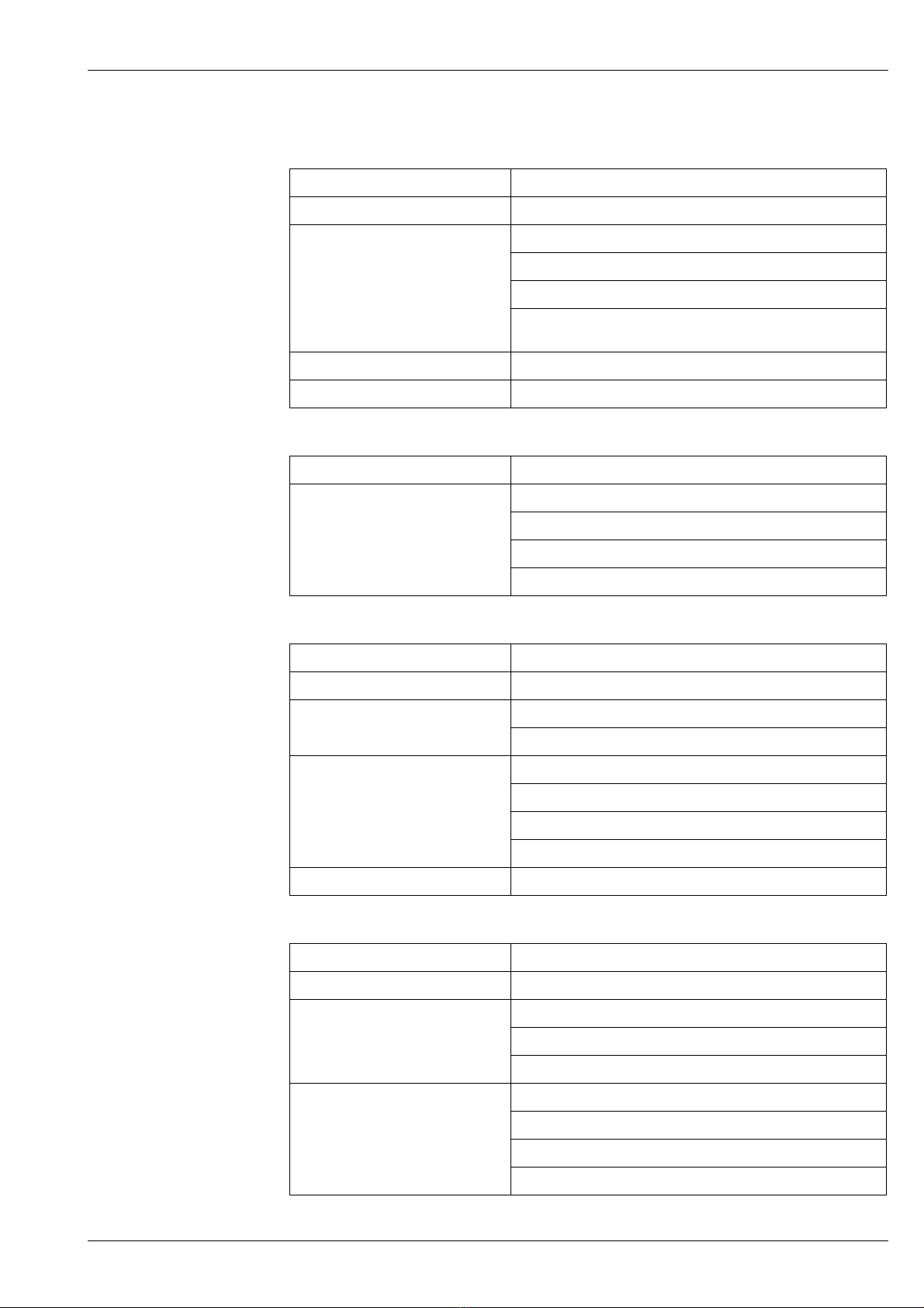
The following cable entries are available:
•G (PF) 1/2"
•NPT 1/2"
•PG 16
•M 20
Caution!
Please prepare a metal cable gland (not a plastic one) that has shield cable grounding
functionality to meet the condition of EMC certification.
No cable gland is provided with the NMT 539 as standard.
Size and condition of the communication cable must meet the requirements of intrinsically safe
HART communication.
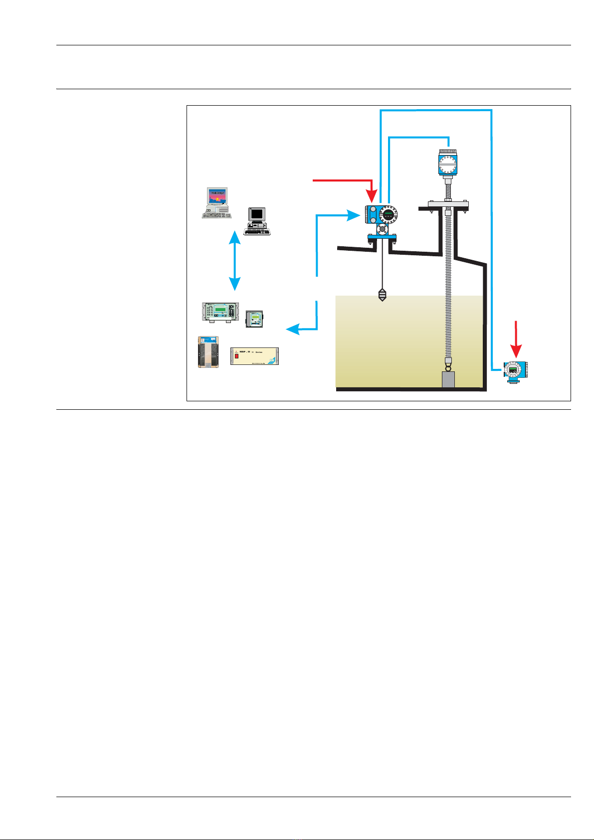
Process connection Converter only version
NMT 539's HART converter can fit onto third party average temperature probes with the following
mechanical connection size and type:
•PF3/4" (equivalent to NPS 3/4") universal coupling.... Housing type 1
•M20 threaded.... housing type 2, specific design to fit to Varec 1700 terminal housing
Note!
Use seal tape to secure the connection between converter and temperature probe.
Please refer to the NMT 539 instruction manual for the detailed installation procedure.
Converter + Temp. , Converter + WB, Converter + Temp. + WB version
All three versions have the same installation method to fit onto the tank nozzle.
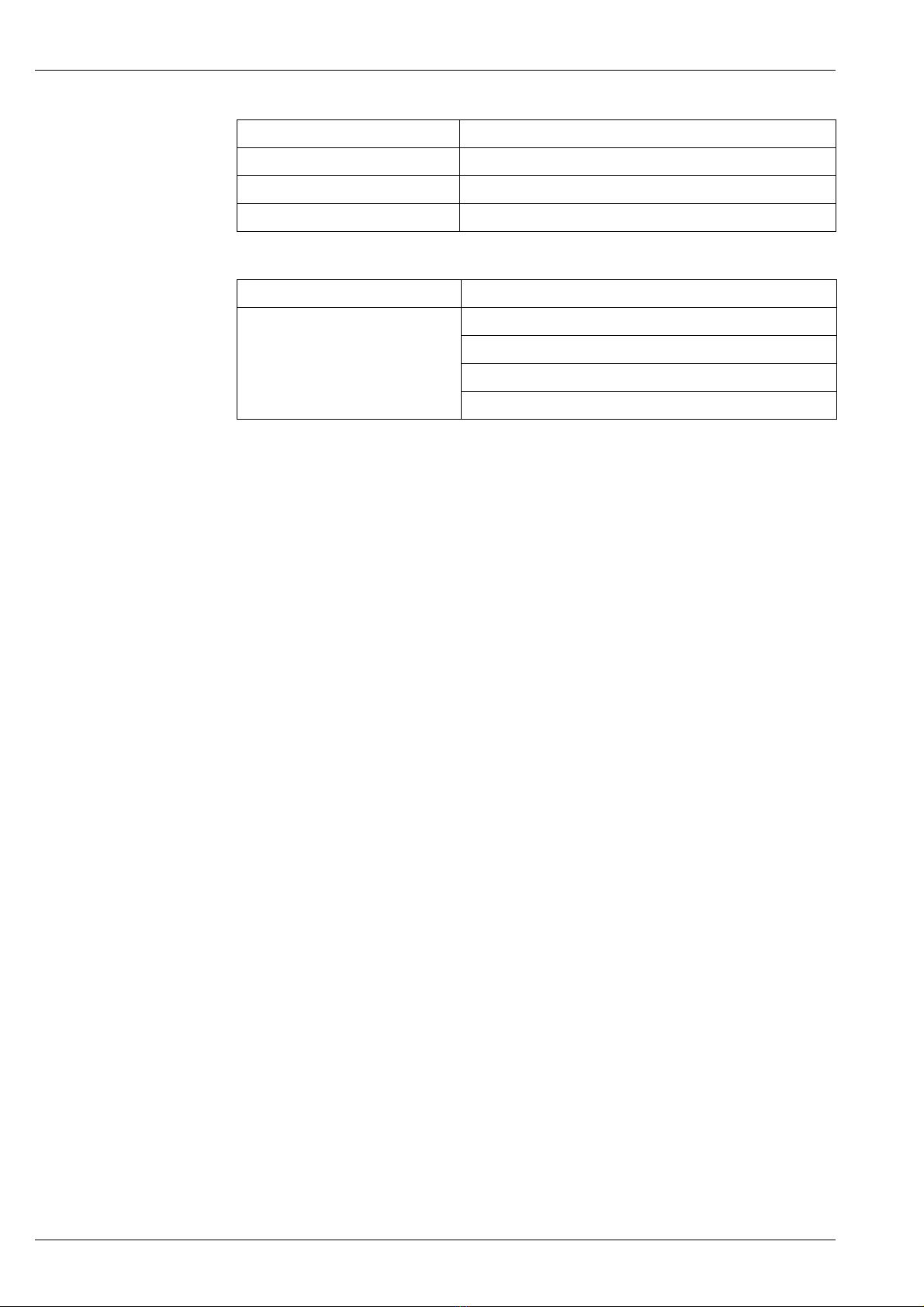
The following flange sizes are available:
•JIS 10K 50A RF... mild carbon
•ANSI 150lb 2" RF... mild carbon
•JPI 150lb 2" RF... mild carbon
•DIN DN50 PN 10RF... mild carbon
Different sizes and materials can be provided depending on the installation conditions. Please
consult your Endress+Hauser representative for the most suitable solution.
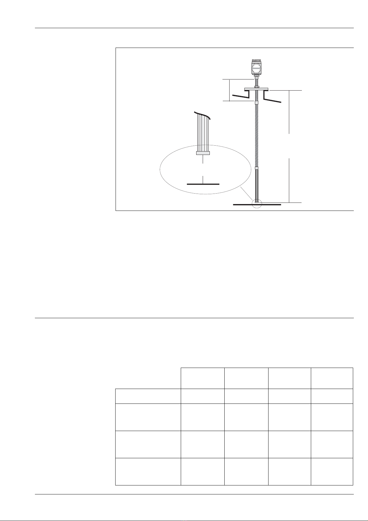
The installation height
adjuster
An additional feature of the NMT 539, the height adjuster, can be used to adjust installation height
of the NMT 539 within ±180 mm (7") from original height.
Note!
The height adjuster is not included in "Converter only" version.
Caution!
Please tighten the lock nut with seal tape to secure rigidity of the NMT 539 at the end of physical
installation and/or if the height adjuster will be used during operation. A loose lock nut can lead
to improper tank sealing or unexpected leakage into the tank.
WB blocking distance The Water Bottom sensor can be set as low as zero clearance from the tank floor by using height
adjuster. Due to mechanical design of WB sensor, bottom plate has approximately 10mm
thickness. This will become a blocking distance (ineffective measuring range).
Caution!
Calculate vertical movement of NMT 539 installation height prior to setting the WB sensor bottom
clearance. Typical tank shell deformation causes vertical movement at a minimum 20 ~ 30mm
(1"). Excessive weight load of entire NMT 539 on WB sensor by contacting tank floor may cause
critical damage that disables accurate & stable WB level measurement.