•5 •
DC CONNECTION PRECAUTIONS5.
Connect and disconnect the DC output clips only after pressing the5.1
START/STOP( )buttontoturntheoutputoffandremovingtheACplug
from the electrical outlet. Never allow the clips to touch each other.
Attach the clips to the battery and chassis, as indicated in steps 6.5, 6.65.2
and 7.2 through 7.4.
FOLLOW THESE STEPS WHEN BATTERY IS INSTALLED IN6.
VEHICLE.
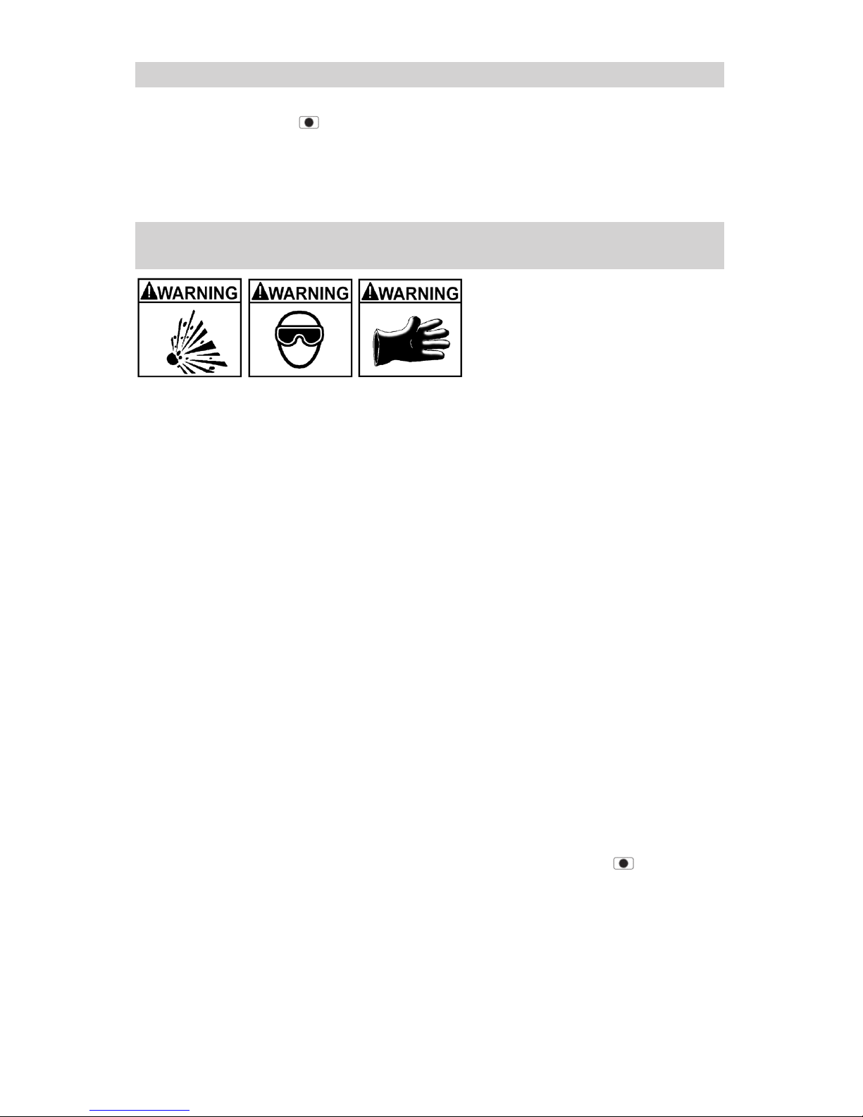
A spark near the battery may
cause a battery explosion. To
reduce the risk of a spark near
the battery:
Position the AC and DC cables to reduce the risk of damage by the hood,6.1
door and moving or hot engine parts.
Stay clear of fan blades, belts, pulleys and other parts that can cause6.2
injury.
Checkthepolarityofthebatteryposts.ThePOSITIVE(POS,P,+)battery6.3
postusuallyhasalargerdiameterthentheNEGATIVE(NEG,N,-)post.
Determinewhichpostofthebatteryisgrounded(connected)tothechas-6.4
sis.Ifthenegativepostisgroundedtothechassis(asinmostvehicles),
see step 6.5. If the positive post is grounded to the chassis, see step 6.6.
Foranegative-groundedvehicle,connectthePOSITIVE(RED)clipfrom6.5
thebatterychargertothePOSITIVE(POS,P,+)ungroundedpostofthe
battery.ConnecttheNEGATIVE(BLACK)cliptothevehiclechassisor
engine block away from the battery. Do not connect the clip to the carbure-
tor, fuel lines or sheet-metal body parts. Connect to a heavy gauge metal
part of the frame or engine block.
Forapositive-groundedvehicle,connecttheNEGATIVE(BLACK)clip6.6
fromthebatterychargertotheNEGATIVE(NEG,N,-)ungroundedpost
ofthebattery.ConnectthePOSITIVE(RED)cliptothevehiclechassisor
engine block away from the battery. Do not connect the clip to the carbure-
tor, fuel lines or sheet-metal body parts. Connect to a heavy gauge metal
part of the frame or engine block.
Whendisconnectingthecharger,presstheSTART/STOP(6.7 )button
to turn the output off, disconnect the AC cord, remove the clip from the
vehicle chassis and then remove the clip from the battery terminal.
See CALCULATING CHARGE TIME for length of charge information.6.8