DTS Synergy 7 Profile User manual


User Manual Ver. 1.08 1 di 39
SYNERGY 7 PROFILE
Release 1.08
Code: 0517I360
For more information
Language EN
Art-Net™ Designed by and Copyright Artistic Licence Holdings Ltd
All other trademarks, both marked and not marked, are the property of their respective owners.

User Manual Ver. 1.08 2 di 39
SYNERGY 7 PROFILE
ITA
Le informazioni contenute in questo documento sono state attentamente redatte e controllate. Tuttavia non è
assunta alcuna responsabilità per eventuali inesattezze. Tutti i diritti sono riservati e questo documento non può
essere copiato, fotocopiato, riprodotto per intero o in parte senza previo consenso scritto della D.T.S.
Illuminazione.
D.T.S. Illuminazione si riserva il diritto di apportare senza preavviso cambiamenti e modifiche estetiche funzionali
o di design a ciascun proprio prodotto. D.T.S. Illuminazione non assume alcuna responsabilità sull’uso o
sull’applicazione dei prodotti o dei circuiti descritti.
ENG
The information contained in this publication has been carefully prepared and checked. However, no
responsibility will be taken for any errors. All rights are reserved and this document cannot be copied,
photocopied or reproduced, in part or completely, without prior written consent from D.T.S. Illuminazione
D.T.S. Illuminazione reserves the right to make any aesthetic, functional or design modifications to any of its
products without prior notice. D.T.S. Illuminazione takes no responsibility for the use or application of the products
or circuits described herein.
FRA
Les informations contenues dans le présent manuel ont été rédigées et contrôlées avec le plus grand soin. Nous
déclinons toutefois toute responsabilité en cas d'éventuelles inexactitudes. Tous droits réservés. Ce document
ne peut être copié, photocopié ou reproduit, dans sa totalité ou partiellement, sans le consentement préalable
de D.T.S. Illuminazione.
D.T.S. Illuminazione. se réserve le droit d'apporter toutes modifications et améliorations esthétiques,
fonctionnelles ou de design, sans préavis, à chacun de ses produits. D.T.S. Illuminazione décline toute
responsabilité sur l'utilisation ou sur l'application des produits ou des circuits décrits.
ESP
Las informaciones contenidas en este documento han sido cuidadosamente redactadas y controladas. Con todo,
no se asume ninguna responsabilidad por eventuales inexactitudes. Todos los derechos han sido reservados y
este documento no puede ser copiado, fotocopiado o reproducido, total o parcialmente, sin previa autorización
escrita de D.T.S. Illuminazione.
D.T.S. Illuminazione se reserva el derecho a aportar sin previo aviso cambios y modificaciones de carácter
estético, funcional o de diseño a cada producto suyo. D.T.S. Illuminazione no se asume responsabilidad de
ningún tipo sobre la utilización o sobre la aplicación de los productos o de los circuitos descritos.

User Manual Ver. 1.08 3 di 39
SYNERGY 7 PROFILE
Table of Contents
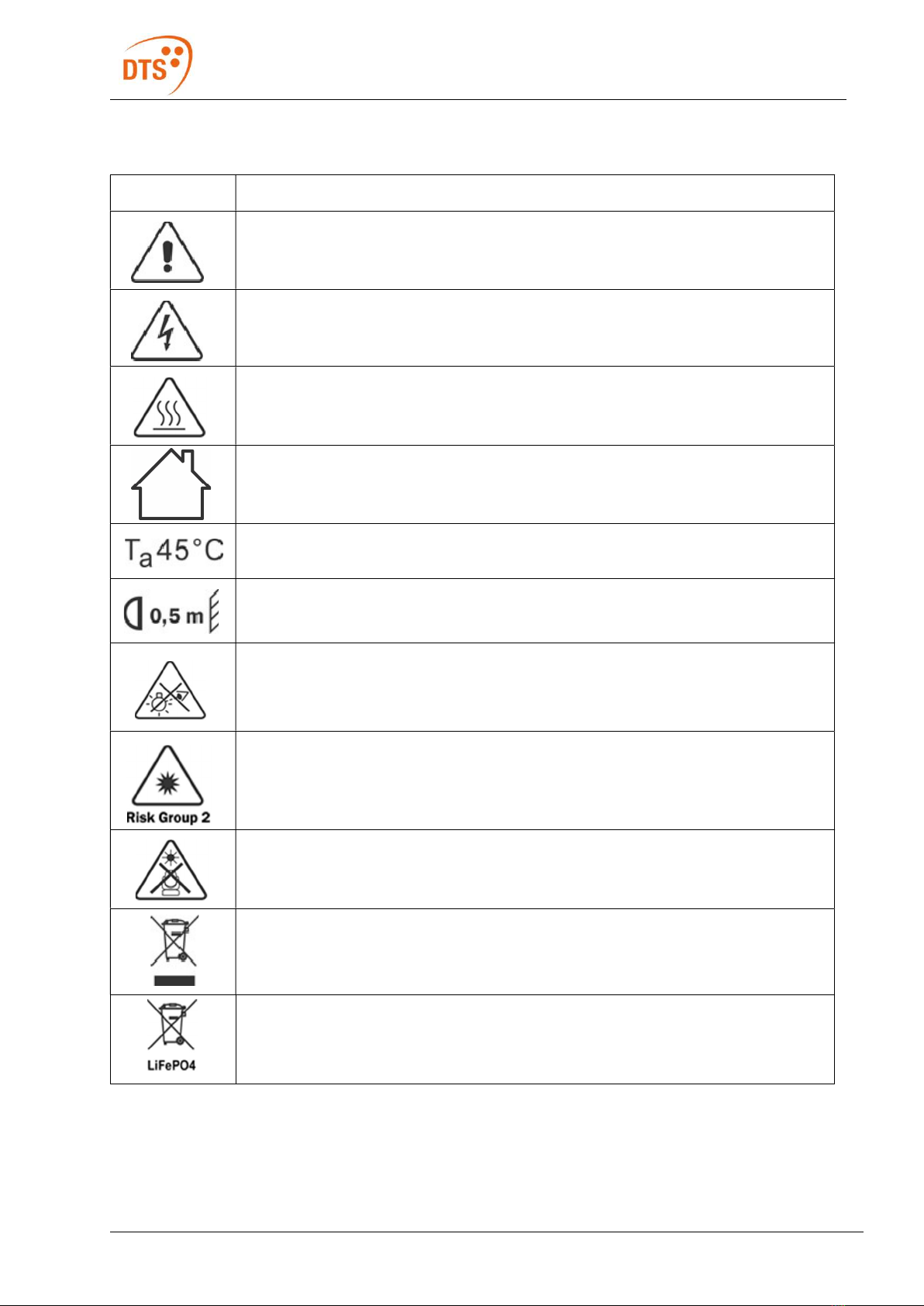
1 Symbols........................................................................................................................................................ 5
2 General Warning .......................................................................................................................................... 6
3 Important Safety Information ........................................................................................................................ 6
3.1 Fire Prevention ..................................................................................................................................... 6
3.2 Prevention of Electric Shock ................................................................................................................ 6
3.3 Safety ................................................................................................................................................... 7
3.4 Level of Protection Against the Penetration of Solid and Liquid Objects ............................................. 8
3.5 Waste Electrical and Electronic Equipment (WEEE) Directive: ........................................................... 8
3.6 Waste Electrical and Electronic Equipment (WEEE) Directive: ........................................................... 8
4 General Warranty Conditions ....................................................................................................................... 8
5 Technical Features ....................................................................................................................................... 8
5.1 Output .................................................................................................................................................. 8
5.2 Optical Group ....................................................................................................................................... 9
5.3 Color Generation .................................................................................................................................. 9
5.4 Iris ........................................................................................................................................................ 9
5.5 Dynamic Effects ................................................................................................................................... 9
5.6 Framing System ................................................................................................................................... 9
5.7 User interface ....................................................................................................................................... 9
5.8 Control ................................................................................................................................................. 9
5.9 Pan & Tilt ........................................................................................................................................... 10
5.10 Power Supply ..................................................................................................................................... 10
5.11 Connections ....................................................................................................................................... 10
5.12 Internal Protection Devices ................................................................................................................ 10
5.13 Operating Temperature ...................................................................................................................... 10
5.14 Storage Temperature ......................................................................................................................... 10
5.15 Physical .............................................................................................................................................. 10
5.16 Dimensions ........................................................................................................................................ 11
6 Pan / Tilt Lock............................................................................................................................................. 12
7 Included Items ............................................................................................................................................ 12
8 Accessories on Request............................................................................................................................. 12
9 Installation .................................................................................................................................................. 13
9.1 Safety Cable ...................................................................................................................................... 14
10 Mains Connection....................................................................................................................................... 15
10.1 Protection ........................................................................................................................................... 15
11 DMX Signal Connection ............................................................................................................................. 15
11.1 DMX Modes ....................................................................................................................................... 16
11.2 Setting Up the DMX Address ............................................................................................................. 16
12 Art-Net / sACN Signal Connection ............................................................................................................. 16
12.1 Direct Ethernet Operation .................................................................................................................. 17
12.2 Ethernet to RDM/DMX Operation ...................................................................................................... 17
13 Updating the Firmware ............................................................................................................................... 18

User Manual Ver. 1.08 4 di 39
SYNERGY 7 PROFILE
14 Rotating Framing System ........................................................................................................................... 19
15 Display Functions ....................................................................................................................................... 20
16 Error Messages .......................................................................................................................................... 27
17 Motors and LED Driver PCBs References .................................................................................................. 30
18 Opening the Housing .................................................................................................................................. 31
19 Rotating Gobo Dimensions ........................................................................................................................ 32
20 Periodic Cleaning........................................................................................................................................ 33
20.1 Lenses and Filters .............................................................................................................................. 33
20.2 Fans and Air Passages ...................................................................................................................... 33
21 Periodic Check-ups ..................................................................................................................................... 33
21.1 Mechanical Parts ................................................................................................................................ 34
21.2 Electrical Components ....................................................................................................................... 34
22 Rotating Gobo Wheel 1 .............................................................................................................................. 35
23 Rotating Gobo Wheel 2 .............................................................................................................................. 36
24 Filters Wheel ............................................................................................................................................... 37
25 Color Wheel ................................................................................................................................................ 38
NOTES ................................................................................................................................................................ 39

User Manual Ver. 1.08 5 di 39
SYNERGY 7 PROFILE
1 Symbols
Symbol Meaning
General risk.
Electric shock risk
Hot surface
Suitable for indoor use only.
Maximum operating ambient temperature.
Minimum distance from illuminated objects.
Do not stare at the operating light source.
Photobiological safety risk group2
Never expose the front lens to sunlight or any strong artificial Light source from any
angle to avoid damage of head internal parts.
European Community Directive 2012/19/EU on Waste Electrical and Electronic
Equipment (WEEE).
Dispose the battery at the end of its life according to the regulation in force

User Manual Ver. 1.08 6 di 39
SYNERGY 7 PROFILE
2 General Warning
Carefully read the instruction contained in this User Manual, as they give important information regarding your
safety and others during installation, use, and maintenance of the product.
The unit is not suitable for domestic use and must be installed by qualified personnel only.
The device must always be equipped with an efficient ground connection.
3 Important Safety Information
3.1 Fire Prevention
Minimum distance from illuminated surface: 0.5 m
Never expose the front lens, from any angle, to direct sunlight or strong
artificial light sources to avoid damage to internal parts of the product.
The front lens may act as a powerful magnifying glass if exposed towards the
sun or any strong artificial light source; this will cause damage to the internal
parts of the moving head, even if exposed for a few seconds, and even when
the unit is turned off.
It is strongly recommended to leave the front lens directed towards the
ground when switching off or leaving the unit unattended.
The unit features various air inlets and cooling fans located on both the base
and the head of the fixture. Under no circumstances should these be blocked
or obstructed whilst the projector is operating. Doing so may cause the fixture
to seriously overheat, damaging it and compromising its proper operation.
Each fixture produces heat and must be installed in a well-ventilated place.
Connect the projector to mains power via a thermal magnetic circuit breaker.
3.2 Prevention of Electric Shock
High voltage is present inside the unit.
Unplug the unit prior to performing any function which involves handling of
the insides of all parts of the product.
Class I appliance: connection must be made to a mains system fitted with an
efficient earthing.
SYNERGY 7 PROFILE requires the assistance of specialized personnel for all
servicing. Please always refer to an authorized DTS service center.

User Manual Ver. 1.08 7 di 39
SYNERGY 7 PROFILE
3.3 Safety
Risk Group 2 product according to IEC 62471.
Do not look directly at the light output and do not stare at the light beam
through optical instruments or any other device that may concentrate the light
beam. May be harmful to the eyes and skin.
Do not stare at the operating light source.
The luminaire should be positioned so that prolonged staring into the
luminaire from a minimum distance of 40.39 m is not expected.
The light source contained in this luminaire shall only be replaced by the
manufacturer or their service agent or a similar qualified person.
The unit is not suitable for domestic use and must be installed by qualified personnel
only.
The projector should always be installed with the proper tools. The fixing point must
always be capable of supporting the weight of the unit.
Always use a safety cable to sustain the weight of the unit in case of failure of the
main fixing point.
Pan: 540° rotation; Tilt: 260° rotation.
Never obstruct the projector’s movement while it is operating.
The external surface of the unit’s body, at various points, may exceed 50 °C.
Never handle the unit until at least five minutes have passed since it was
turned off.
Ambient temperature should not exceed 45 °C.
This fixture is intended for use where humidity does not exceed 90% (non-
condensing).
After storage, and before switching on the fixture, please ensure that its ambient
temperature has been restored to acceptable values.
Never install the fixture in places that lack a constant air flow.

User Manual Ver. 1.08 8 di 39
SYNERGY 7 PROFILE
3.4 Level of Protection Against the Penetration of Solid and Liquid
Objects
The projector is classified as an ordinary appliance and its protection level
against the penetration of solid and liquid objects is IP20.
The projector contains electric and electronic components which should under no
circumstances come into contact with oil, water, or any other liquid. The proper
functioning of the unit would be compromised should this occur.
Suitable for indoor use only.
3.5 Waste Electrical and Electronic Equipment (WEEE) Directive:
The projector, the accessories, and the packaging should be sorted for
environmental-friendly recycling.
For EC countries: according to the European Directive 2012/19/EU for Waste
Electrical and Electronic Equipment and its implementation into national right,
luminaires that are no longer usable must be collected separately and disposed of in
an environmentally correct manner.
3.6 Waste Electrical and Electronic Equipment (WEEE) Directive:
The projector contains a rechargeable lead-acid or lithium iron tetraphosphate
battery. To preserve the environment, please dispose the battery at the end of
its life according to the regulation in force.
4 General Warranty Conditions
The unit is guaranteed for 36 months from the date of purchase against manufacturing material defects.
The warranty covers defects in materials and workmanship. The warranty is not applicable where a defect is
caused by misuse or unauthorized repair of the product.
Any functional or/and physical modification of the product is not allowed.
5 Technical Features
5.1 Output
1.050 W pure white LED source (Lumen output: 55,000 lm @ Color temperature output: 7,000 K)
Native CRI > 75; Higher CRI (DMX-selectable) CRI >90 (R9 >80);
Average LED life: 50,000 hours (70% lumen output)

User Manual Ver. 1.08 9 di 39
SYNERGY 7 PROFILE
5.2 Optical Group
101,000 Lux (7° @ 5 m)
7° - 52° linear zoom with autofocus
Linear soft frost filter
Electronic dimmer / shutter / strobe (0.3 to 33.3 Hz)
5.3 Color Generation
Linear CMY
Linear CTO (7,000 K – 3,000 K)
Gel filters emulation
4-color wheel (white correction + UV)
5-color wheel (with double/continuous color generation)
5.4 Iris
Linear 16-blade iris (15% ÷ 100%)
5.5 Dynamic Effects
Dynamove FX Engine (DTS Patent)
Virtual Animation Wheel
2 customizable rotating 6-gobo wheel
Circular 24-facet rotating prism
Linear 6-facet rotating prism
5.6 Framing System
4-blade rotating framing system
Real ‘curtain’ effect for each blade
60° rotation for each blade (+/- 30°)
90° full system rotation (+/- 45°)
5.7 User interface
LCD graphic display + 4 soft keys (“auto-flip” and “key-lock” functions available)
Li-Fe backup battery for controlling display settings when the unit is not powered
5.8 Control
Art-Net 4, sACN, RDM/DMX 512 protocols
52 DMX channels (Default)
61 DMX channels
16-bit index for insertion and rotation of each blade

User Manual Ver. 1.08 10 di 39
SYNERGY 7 PROFILE
16-bit index for blade system rotation
“Standard”, “Silent” and “Ultra-silent” operation modes
Noise level in “Ultra-silent” mode: 36dBA @ 1 m (normal operation, full power)
Internal operating system updatable via DTS firmware uploader dongle
5.9 Pan & Tilt
Pan: 540°
Tilt: 260°
Tri-phase stepper motor technology
16-bit resolution
Pan / Tilt lock
5.10 Power Supply
Wide-range 100-240 Vac 50/60 Hz
Power consumption: 1,400 W max
Power Factor: PF >0.90
5.11 Connections
DMX: XLR 3-pole and 5-pole In / Out panel connectors
Power supply: powerCON TRUE1 panel connector
Art-Net / sACN: etherCON RJ45 panel connector
5.12 Internal Protection Devices
Overvoltage and over temperature circuits protection
Auto-parking: internal collision protection system
5.13 Operating Temperature
-10 °C / 45 °C
5.14 Storage Temperature
-20 °C / 60 °C
5.15 Physical
IP20
Weight: 46.5 kg
Finishing: Black

User Manual Ver. 1.08 11 di 39
SYNERGY 7 PROFILE
5.16 Dimensions

User Manual Ver. 1.08 12 di 39
SYNERGY 7 PROFILE
6 Pan / Tilt Lock
When moving or servicing the unit, you can lock the pan and tilt movements.
To lock or release the pan and tilt, follow the instructions as seen below:
7 Included Items
1x PowerCON TRUE1 female connector (code 0520P066)
2x Omega clamp with ¼- turn “Fast Lock” connection (code 02K00549)
8 Accessories on Request
Aliscaf clamp for Ø 48-51 mm tube - max load 200 Kg (code 0521A033)
Indicated for any kind of loads, both vertical and/or horizontal.

User Manual Ver. 1.08 13 di 39
SYNERGY 7 PROFILE
Professional G-QUICK clamp - max load 100 Kg (code 0521A037)
Not indicated for horizontal load.
Safety cable 5 x 600 mm (Max load 60 Kg) (code 0521A038)
DTS firmware uploader dongle (code 03.LA.206)
9 Installation
The unit is suitable for dry locations only.
SYNERGY 7 PROFILE may be either floor or ceiling mounted.
For floor mounting installations, SYNERGY 7 PROFILE is supplied with four rubber mounting feet on the base.
For ceiling mounted installations, DTS recommend the use of appropriate clamps to fix the unit to the mounting
surface.
The supporting structure from which the unit is hung should be capable of bearing the weight of the unit, as
should any clamps used to hang it.
The structure should also be sufficiently rigid as not to move or shake whilst the SYNERGY 7 PROFILE is
moving.
Four ¼-turn “Fast Lock” connections placed in the base of the unit allow SYNERGY 7 PROFILE to hang by
using two Omega brackets (provided with the unit) in conjunction with an Aliscaf clamp (available on demand).

User Manual Ver. 1.08 14 di 39
SYNERGY 7 PROFILE
9.1 Safety Cable
A safety cable must be securely fixed to SYNERGY 7 PROFILE and to the suspension truss in
order to avoid the fixture accidentally falling, should the main fixing point fail.
The safety cable used must be approved by a notified body according to IEC 60598-2-17 and
must be capable of bearing at least 10 times the weight of the unit. For more information,
please refer to an authorized DTS service center.
A suitable safety cable (code 0521A038) is available on demand.
You may attach the safety cable to the attachment point (A) located at the base of the fixture, as shown in the
picture below.
A

User Manual Ver. 1.08 15 di 39
SYNERGY 7 PROFILE
10 Mains Connection
SYNERGY 7 PROFILE operates at 100-240 Vac 50/60 Hz.
Prior to connecting the unit to the mains, ensure that your local mains electricity supply properties are
compatible with those of the product.
For connection purposes, ensure that your plug is capable of supporting 6,5 A at 230 Vac or 14 A at 100 Vac
for each unit connected.
Strict adherence to regulatory norms is strongly recommended.
10.1 Protection
The use of a thermal magnetic circuit breaker is recommended for each unit.
Class I appliance: connection must be made to a mains system fitted with an efficient earthing.
11 DMX Signal Connection
• The unit operates using the digital USITT DMX512 signal.
• Connection between the light controller and the projector, or between projectors, must be carried out using a
two-pair screened ø 0.5 mm cable, and a XLR 5 or 3 pins connector.
• Ensure that the conductors do not touch each other. Do not connect the ground cable to the XLR chassis.
The housing of the plug must be isolated.
• Connect the light controller to the DMX IN panel connector of the projector; to create a link to the next
projector, simply connect the DMX OUT plug of the former to the DMX IN plug of the new fixture in line.
Following this procedure, all the projectors will be cascade connected.
PS. If the display showing the DMX address flashes, then one of the following errors has occurred:
- DMX signal not present
- DMX reception problem
MAINS IN
100 - 240 Vac 50 / 60Hz
male PowerCON TRUE1 panel connector

User Manual Ver. 1.08 16 di 39
SYNERGY 7 PROFILE
The use of a DMX terminator is recommended.
The DMX terminator is a male XLR 3- or 5-pins connector with a 120 Ω resistor between pin 2 and pin 3.
The DMX terminator must be plugged in into the last unit’s DMX OUT panel connector of the DMX line.
Place a 120 Ω resistor between pin 2 and 3 of a male XRL
connector;
Plug the resistor into the DMX OUT panel connector of the last unit
connected to the DMX line.
11.1 DMX Modes
SYNERGY 7 PROFILE can be controlled with 52 DMX channels (Default) or 61 DMX channels.
e.g., when using the unit in 52 DMX channels mode (Default), set the following addresses on the light desk:
Projector 1 A001
Projector 2 A053 If you want to select the next projector, just add “52” to the former DMX address
Projector 3 A105
….. A….
projector 6 A261
11.2 Setting Up the DMX Address
1 Press the UP and DOWN key until you reach the desired DMX address. The numbers on the display will
start flashing (new DMX address hasn't yet been set).
2 Press ENTER to confirm your selection. The numbers on the display will stop flashing; the projector is now
set to the new DMX address.
TIP: if you keep pressed down the UP or DOWN keys, address scrolling will be quicker allowing thus for a
faster selection.
12 Art-Net / sACN Signal Connection
SYNERGY 7 PROFILE can be controlled through Art-Net / sACN signals.
Connection between the light controller and the projector must be carried out using a category 5 network cable
and a standard RJ45 connector.

User Manual Ver. 1.08 17 di 39
SYNERGY 7 PROFILE
12.1 Direct Ethernet Operation
For direct Ethernet operation, connect the light controller’s Art-Net / s-ACN output signal via Ethernet switch to
each unit’s etherCON RJ45 IN connector.
For each unit, scroll to “NETWORK” menu (refer to the paragraph “Display Function” for further details):
Inside the “INPUT” menu, select “Art-Net” or “sACN” as input control signal.
Inside the “IP ADDRESS MODE” menu, select “Default” or “Static” mode.
Inside the “ETH TO DMX” menu, select ON.
Set the IP address and Net Mask. IP address must be different for each unit on a network.
Set the Art-Net or sACN Universe.
DMX address: 1 DMX address: 53 DMX address: 105
IP address: 002.214.192.007 IP address: 002.214.192.008 IP address: 002.214.192.009
Universe: 1 Universe: 1 Universe: 1
12.2 Ethernet to RDM/DMX Operation
For Ethernet to RDM/DMX operation, connect the light controller’s Art-Net / s-ACN output signal via Ethernet
switch to the etherCON RJ45 input connector of the first unit only.
In this configuration, the first unit works as an Ethernet-to-DMX converter and sends RDM/DMX signal to its
DMX output connector. All the other units must be connected as a DMX chain with standard DMX settings.
Only for the first unit, scroll until reaching “NETWORK” menu (refer to DISPLAY FUNCTIONS for details):
Inside the “INPUT” menu, select “Art-Net” or “sACN” as input control signal.
Inside the “IP ADDRESS MODE” menu, select “Default” or “Static” mode.
Inside the “ETH TO DMX” menu, select ON.
Set the IP address and Net Mask. IP address must be different for each unit on a network.
Set the Art-Net or sACN Universe.

User Manual Ver. 1.08 18 di 39
SYNERGY 7 PROFILE
DMX address: 1 DMX address: 53 DMX address: 105
IP address: 002.214.192.007
Universe: 1
DMX address: 1 DMX address: 53 DMX address: 105
IP address: 002.214.192.008
Universe: 2
The use of a DMX terminator is recommended.
Please refer to page 16 for further information DMX terminators.
13 Updating the Firmware
In order to update to the latest firmware release of the SYNERGY 7 PROFILE, you will need:
DTS firmware uploader dongle (code 03.LA.206).
“DTS Firmware Upgrade Utility v.2.02” program installed on PC (Windows OS).
Latest firmware release available for the SYNERGY 7 PROFILE.
Updating to the latest firmware release:
To perform the update, please follow the procedure as described below:
1 Connect the DTS Firmware Uploader Dongle to a spare USB port on the PC.
2 Connect the unit’s DMX IN to the DTS Firmware Uploader Dongle’s DMX OUT with a standard DMX cable
and turn on the fixture.
3 Send the new firmware release into the unit by using “DTS Firmware Upgrade Utility v.2.02” program. At
the end of the procedure, the unit will commence a reset.
For more information, please refer to an authorized DTS service center.
Other manuals for Synergy 7 Profile
1
Table of contents
Other DTS Dj Equipment manuals

DTS
DTS MINI BRICK User manual

DTS
DTS PROFLO LED 200 CT User manual

DTS
DTS Wonder D User manual

DTS
DTS X BRICK User manual

DTS
DTS 03.MS014.EBLFP User manual

DTS
DTS XR2000 SPOT CMY User manual

DTS
DTS DOCTUS Series User manual

DTS
DTS NICK NRG 1401 User manual

DTS
DTS EUPHONY 3 User manual

DTS
DTS NICK NRG 1401 User manual

DTS
DTS SCENA LED 200 Series User manual

DTS
DTS ARTEMIO PROFILE User manual

DTS
DTS Synergy 7 Profile User manual

DTS
DTS Portfolio User manual

DTS
DTS SOPRANO Series User manual

DTS
DTS DELTA 10 F User manual

DTS
DTS X-BRICK User manual

DTS
DTS ALCHEMY 5 User manual

DTS
DTS SCENA LED 80 CT User manual

DTS
DTS Titan HP User manual