manuals.online logo
Brands
  1. Home
  2. •
  3. Brands
  4. •
  5. DTS
  6. •
  7. Dj Equipment
  8. •
  9. DTS DELTA 10 F User manual

DTS DELTA 10 F User manual

Other manuals for DELTA 10 F

1

Other DTS Dj Equipment manuals

DTS Wonder D User manual

DTS

DTS Wonder D User manual

DTS X BRICK User manual

DTS

DTS X BRICK User manual

DTS Synergy 7 Profile User manual

DTS

DTS Synergy 7 Profile User manual

DTS Synergy 7 Profile User manual

DTS

DTS Synergy 7 Profile User manual

DTS Portfolio User manual

DTS

DTS Portfolio User manual

DTS XR2000 SPOT CMY User manual

DTS

DTS XR2000 SPOT CMY User manual

DTS SCENA LED 120 HQS User manual

DTS

DTS SCENA LED 120 HQS User manual

DTS PROFLO LED 200 CT User manual

DTS

DTS PROFLO LED 200 CT User manual

DTS XR2000 SPOT CMY User manual

DTS

DTS XR2000 SPOT CMY User manual

DTS NICK NRG 501 User manual

DTS

DTS NICK NRG 501 User manual

DTS XR250 WASH User manual

DTS

DTS XR250 WASH User manual

DTS SCENA LED 200 Series User manual

DTS

DTS SCENA LED 200 Series User manual

DTS EUPHONY 3 User manual

DTS

DTS EUPHONY 3 User manual

DTS ARTEMIO PROFILE User manual

DTS

DTS ARTEMIO PROFILE User manual

DTS DOCTUS Series User manual

DTS

DTS DOCTUS Series User manual

DTS 03.MS014.EBLFP User manual

DTS

DTS 03.MS014.EBLFP User manual

DTS NICK NRG 1401 User manual

DTS

DTS NICK NRG 1401 User manual

DTS BRICK User manual

DTS

DTS BRICK User manual

DTS Titan HP User manual

DTS

DTS Titan HP User manual

DTS Synergy 5 Spot User manual

DTS

DTS Synergy 5 Spot User manual

DTS SOPRANO Series User manual

DTS

DTS SOPRANO Series User manual

DTS ALCHEMY 5 User manual

DTS

DTS ALCHEMY 5 User manual

DTS NICK NRG 1401 User manual

DTS

DTS NICK NRG 1401 User manual

DTS SCENA LED 80 CT User manual

DTS

DTS SCENA LED 80 CT User manual

Popular Dj Equipment manuals by other brands

MAGMATIC Prisma Wash 25 user manual

MAGMATIC

MAGMATIC Prisma Wash 25 user manual

HERA PROCOLOR 60 RGBW SERIES User manual & installation guide

HERA

HERA PROCOLOR 60 RGBW SERIES User manual & installation guide

EuroLite LED TSL-600 SCAN COB user manual

EuroLite

EuroLite LED TSL-600 SCAN COB user manual

Ledj Slimline 12HEX12 user manual

Ledj

Ledj Slimline 12HEX12 user manual

Laserworld Garden GS-50RG Xmas manual

Laserworld

Laserworld Garden GS-50RG Xmas manual

Chauvet OVATION E-930VW Quick reference guide

Chauvet

Chauvet OVATION E-930VW Quick reference guide

Snow Masters Zig Oscillator user manual

Snow Masters

Snow Masters Zig Oscillator user manual

EuroLite 50530554 user manual

EuroLite

EuroLite 50530554 user manual

Beamz BUV243 user manual

Beamz

Beamz BUV243 user manual

Eagletone 6 Eyes Flower user manual

Eagletone

Eagletone 6 Eyes Flower user manual

EuroLite FLD-1508 user manual

EuroLite

EuroLite FLD-1508 user manual

Technical Pro LG8xSEA user manual

Technical Pro

Technical Pro LG8xSEA user manual

JB Systems Lounge Laser DMX Operation manual

JB Systems

JB Systems Lounge Laser DMX Operation manual

Elation FUZE WASH Z350 user manual

Elation

Elation FUZE WASH Z350 user manual

Maverick MK3 WASH Quick reference guide

Maverick

Maverick MK3 WASH Quick reference guide

Infinity TF-260C7 Fresnel manual

Infinity

Infinity TF-260C7 Fresnel manual

Chauvet EVE E-50Z Quick reference guide

Chauvet

Chauvet EVE E-50Z Quick reference guide

Eliminator Lighting E 138 manual

Eliminator Lighting

Eliminator Lighting E 138 manual

manuals.online logo
manuals.online logoBrands
  • About & Mission
  • Contact us
  • Privacy Policy
  • Terms and Conditions

Copyright 2025 Manuals.Online. All Rights Reserved.

GB
Made in Italy
DELTA 10 F
User’s Manual rel 1.3
D.T.S. Illuminazione srl - ITALY
http://www.dts-lighting.it
IP65
03.LDF004.T12
03.LDF004.T25
03.LDF004.T45
03.LDF004.T12.WS
03.LDF004.T25.WS
03.LDF004.T45.WS
2 DELTA 10 F
Le informazioni contenute in questo documento sono state attentamente redatte e controllate. Tuttavia
non è assunta alcuna responsabilità per eventuali inesattezze. Tutti i diritti sono riservati e questo
documento non può essere copiato, fotocopiato, riprodotto per intero o in parte senza previo consenso
scritto della D.T.S .
DTS si riserva il diritto di apportare senza preavviso cambiamenti e modifiche estetiche , funzionali o di
design a ciascun proprio prodotto. D.T.S non assume alcuna responsabilità sull’uso o sull’applicazione
dei prodotti o dei circuiti descritti.
The information contained in this publication has been carefully prepared and checked. However, no
responsibility will be taken for any errors. All rights are reserved and this document cannot be copied,
photocopied or reproduced, in part or completely, without prior written consent from D.T.S.
D.T.S. reserves the right to make any aesthetic, functional or design modifications to any of its products
without prior notice. D.T.S. assumes no responsibility for the use or application of the products or circuits
described herein.
Les informations contenues dans le présent manuel ont été rédigées et contrôlées avec le plus grand
soin. Nous déclinons toutefois toute responsabilité en cas d'éventuelles inexactitudes. Tous droits
réservés. Ce document ne peut être copié, photocopié ou reproduit, dans sa totalité ou partiellement,
sans le consentement préalable de .
se réserve le droit d'apporter toutes modifications et améliorations esthétiques, fonctionnelles ou
de design, sans préavis, à chacun de ses produits. décline toute responsabilité sur l'utilisation ou
sur l'application des produits ou des circuits décrits.
D.T.S
D.T.S.
D.T.S.
Las informaciones contenidas en este documento han sido cuidadosamenteredactadas y
controladas. Con todo, no se asume ninguna responsabilidad por eventuales inexactitudes.
Todos los derechos han sido reservados y este documento no puede ser copiado, fotocopiado
o reproducido, total o parcialmente, sin previa autorizaciónescrita de
se reserva el derecho a aportar sin previo aviso cambios y modificaciones de carácter
estético, funcional o de diseño a cada producto suyo. no se asume responsabilidad de
ningún tipo sobre la utilización o sobre la aplicació
n de los productos o de los circuitos descritos.
D.T.S.
D.T.S.
D.T.S.
3 DELTA 10 F
INDEX:
1- SYMBOLS 4
2- GENERAL WARNING 4
3- GENERAL WARRANTY CONDITION 4
4- TECHNICAL FEATURES 5
5- ACCESSORIES 5
6- IMPORTANT SAFETY INFORMATION 7
6.1 Fire prevention
6.2 Prevention of electric shock
6.3 Protection against direct light radiation
6.4 Safety
6.5 Level of protection against the penetration of solid and liquid matter
7- VOLTAGE AND FREQUENCY 8
8- INSTALLATION 8
8.1 Safety cable
8.2 Protection against liquid
8.3 Movement
8.4 Risk of fire
8.5 Forced ventilation
8.6 Ambient temperature
9- MAINS CONNECTION 9
9.1 Protection:
10- DMX SIGNAL CONNECTION 10
10.1 DMX Addresses
10.2 Selecting the DMX address
11- FIRMWARE UPDATING 11
12- DISPLAY FUNCTIONS 12
13- AUTOMATIC OPERATION 17
13.1 CUPr-RAIn-CU01/CU16-Wh01/Wh16
13.2 ChPr MASTER/SLAVE
13.3 Rec mode
14- PERIODIC CLEANING 19
15- PERIODIC CONTROLS 19
16- REPLACING THE LENSES 20
17- DMX PROTOCOL 21
1- SYMBOLS
Graphic symbols used on this manual
2- GENERAL WARNING
Read the instruction contained in this user manual carefully, as they give important information
regarding safety during installation , use and maintenance.
The device is not for domestic use and must be installed by a qualified electrician or experienced
person.
Always disconnect the device from the mains before replacing the lamp.
The lamp must be replaced if it has been damaged or deformed by prolonged use or overheating.
The device must always be equipped with an efficient ground connection.
3- GENERAL WARRANTY CONDITIONS
The unit is guaranteed for 36 months from the date of purchase against manufacturing material defects.
THIS SYMBOL INDICATES A HOT SURFACE
THIS SYMBOL INDICATES ELECTRIC SHOCK RISK
THIS SYMBOL INDICATES GENERAL RISK
THIS SYMBOL MEANS “DO NOT PLACE THE UNIT ON
INFLAMMABLE SURFACES”
F
!
1M THIS SYMBOL INDICATES THE MINIMUM DISTANCE TO
BE KEPT BETWEEN THE DEVICE AND THE LIT OBJECT
DELTA 10 F
4
5
4- TECHNICAL FEATURES
DELTA 10 F RGBW is a new colour changer with LED technology, with a high protection rating (IP65), ideal
for use both indoors and outdoors.
DELTA 10 F RGBW is the brightest LED colour changer in its category: 8.300 Lux at 5 m.
In fact its light source is composed of 240 LEDs (60 x Red, 60 x Green, 60 x Blue, 60 x White) with 19.500
total lumens.
Five interchangeable lenses sets are available: spot (12°), medium flood (25°), wide flood (45°), elliptical
(15° x 45°) and asymmetrical, offering different light beam projection angles.
The LEDs even distribution pattern featuring the same quantity of red, green, blue and white LEDs
guarantees high mixing quality for RGBW colours and a uniform projection on surfaces, no matter what
colour is used. DELTA 10 F RGBW can generate 16 million colours; colour temperature can be varied over a
linear range from 2800 °K to 6500 °K.
DELTA 10 F RGBW offers an IP65 protection rating, making it suitable for a vast variety of uses, either
outdoors or indoors.
DELTA 10 F RGBW has a full-range AC 90-260 V, 50-60 Hz power supply, and therefore ensures reliable
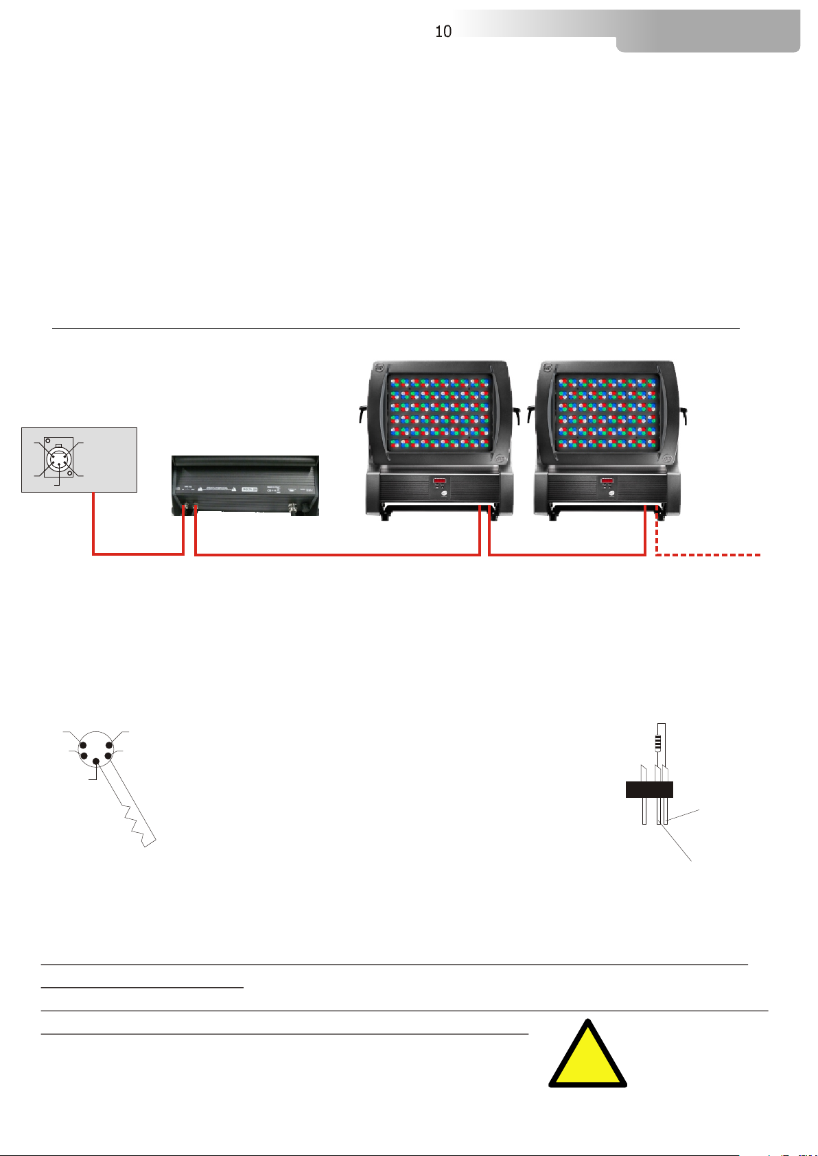
operation even in the case of voltage drops. DELTA 10 F RGBW can be used without external consoles, in
chains of colour changers including up to 32 units.
All functions of the internal DELTA 10 F RGBW menu can be programmed and memorized in a sequence of
events (including different luminosity settings, generation of 16 million different colours, special effects, etc.),
which can be played back in a predetermined sequence over an entire week.
The DELTA 10 F RGBW can operate in vertical, horizontal or inverted positions, and can be positioned on the
floor or ground, or fitted to trusses; it is complete with a practical accessory.
DELTA 10 F is also available as DELTA 10 F CT (240 LEDs: 180 x White, 60 x Amber).
On demand, the unit is also available in RGBA version.
DELTA 10 F RGBW
Code: 03.LDF004.T12 - Spot lenses
Code: 03.LDF004.T25 - Medium flood lenses
Code: 03.LDF004.T45 - Wide Flood lenses
Code: 03.LDF004.T12.WS - Spot lenses, Wireless DMX ready (external Antenna needed)
Code: 03.LDF004.T25.WS - Medium flood lenses, Wireless DMX ready (external Antenna needed)
Code: 03.LDF004.T45.WS - Wide Flood lenses, Wireless DMX ready (external Antenna needed)
LED technology
240 LEDs (60 x Red, 60 x Green, 60 x Blue, 60 x White)
LEDs average lifespan: 100.000 hours
Total luminous flux: 19.500 Lumens
Luminosity: 8.300 Lux at 5 m (12°)
RGBW colour generation (16 million colours)
Colour temperature variable on a linear range (2.800°K÷6.500°K); no infrared / no ultraviolet emissions
Lenses sets
Spot (12°), Medium flood (25°), Wide flood (45°), Elliptical (15° x 45°), Asymmetrical
Lenses sets are interchangeable
User interface
OLED display + 4 buttons; Infrared remote control
Independent operation
Fully programmable via built-in user interface
Master or Slave capability (chains of up to 32 interconnected units)
Control
Remotely controlled by cable or wireless (on request); USITT DMX 512 serial digital protocol (reception /
transmission)
DMX channels: 10
Protection
Full IP65 protection level
DELTA 10 F
6
4- TECHNICAL FEATURES
Power supply / consumption
Full range AC 90-260V, 50-60Hz
Power consumption:
* 90 V – 5,3 A – 480 W * 120 V – 4 A – 480 W
* 230 V – 2,1 A – 480 W * 260 V – 1,85 A – 480 W
Thermal
Operating ambient temperature: -10° / +40°
Weight
18Kg
Finishes
Black, white
Certifications and safety
CE certification; LED class: Class 2 LED product
Dimensions
5- ACCESSORIES
Optional (on request)
• Lenses set Medium flood (25°) (Code: 03.LK.064)
• Lenses set Wide flood (45°) (Code: 03.LK.065)
• Lenses set Elliptical (15° x 45°) (Code: 03.LK.063)
• Diffusion Frost Glass (Code: 0506V022.F)
• Wireless DMX receiver card (Code: 03.LA.012)
• External 2dBi IP65 Omni-directional Antenna (Code: 0508A040)
• “C” Clamp G60 black (max. load 50Kg) (Code: 0521A004)
• “C” Clamp G60 chrome (max. load. 50Kg) (Code: 0521A004.20)
• Safety wire (3mm x 60 cm), ring spring catch, max. capacity load 60Kg (Code: 0521A010)
DELTA 10 F
Unit Dimensions (LxWxH)
454x205x443mm
Weight: 18 Kg
Packaging Dimensions (LxWxH)
630 x 500 x 660 mm
Weight: 20 Kg
454 mm
413 mm205 mm
443 mm
DELTA 10 F
1M
F
!
!
7
6- IMPORTANT SAFETY INFORMATION
6.1 Fire prevention:
-Never locate the fixture on any flammable surface.
-Minimum distance from flammable materials: 1 m.
-Minimum distance from the closest illuminable surface: 1 m.
-Replace any blown or damaged fuses only with those of identical value. Refer to the wiring diagram if
there is any doubt.
-Connect the projector to mains power via a thermal magnetic circuit breaker.
6.2 Prevention of electric shock:
-High voltage is present inside the unit. Isolate the projector from the mains supply prior to performing
any function which involves touching the inside of the unit.
-The level of technology inherent in the DELTA 10 F requires the assistance of specialised personnel for
all servicing.Please refer to an authorised D.T.S. service centre.
-A good earth connection is essential for proper functioning of the projector.
Never connect the unit without proper earth connection.
-The fixture should be located in places with a good air ventilation.
6.3 Protection against direct light radiation:
-Never turn the unit on if any of the lenses or the glass lenses protection is damaged.
-Never look directly the leds when they are on.
6.4 Safety:
-The projector should always be installed with bolts, clamps and other tools that are capable of
supporting the weight of the unit.
-Always use a second safety chain to sustain the weight of the unit in case of the failure of the main
fixing point.
-The external surface of the unit, at various points, may exceed 80°C.
Never handle the unit until it’s on.
-Never install the fixture in an enclosed area lacking sufficient air flow.
-The ambient temperature should not exceed 40°C.
6.5 Level of protection against the penetration of solid and liquid matter:
-The projector is classified as an ordinary appliance and its protection level against the penetration of
solid and liquid matter is IP 65.
8 DELTA 10 F
.7- VOLTAGE AND FREQUENCY:
Delta 10 F can operate at 90-260VAC, 50 or 60 Hz.
8- INSTALLATION:
10 F
10 F
10 F
8.1 Safety cable:
Delta may be either floor or ceiling mounted.
For floor mounting installations, the unit is supplied with four rubber mounting feet on the base.
For ceiling mounted installations, we reccommend the use of appropriate clamps to fix the unit to the
mounting surface.
The supporting structure from which the unit is hung should be capable of bearing the weight of the
unit, as should any clamps used to hung it. The structure should also be sufficiently rigid so as not to
move or shake whilst the Delta is moving.
The Delta is fitted with 7 fixing points on the bottom used to attach accessories (clamps, hooks,
etc.)
.
We recommend the use of a safety cable or chain connected to the Delta 10 F and to the suspension
truss in order to avoid the fixture accidentally falling should the main fixing point fail. Make sure that the
iron cable or chain can bear the weight of the entire unit.
You may attach the safety chain to the holes located on the base of the fixture.
8.2- Protection against liquids
The projector contains electric and electronic components which should under no circumstances come
into contact with oil, water or any other liquid. The proper unit functioning would be compromised
should this occur.
8.3- Movement
The projector has a maximum movement of 90° for Tilt. DO NOT place any obstructions in the path of
the projector's movement.
!
90° 90° !
WARNING
Do not place any object in the path
of the projector’s movement
9 DELTA 10 F
8.4- Risk of fire
Each fixture produces heat and must be installed in a well-ventilated place. The minimum recommended
distance from flammable material is 1 MT.
Minimum distance from the object being illuminated is 1 MT.
8.5- Forced ventilation
You will note, on inspection, that the unit features various air inlets and cooling fans located on the head
of the fixture. These should, under no circumstances, be blocked or obstructed whilst the projector is in
operation.
Doing so could cause the fixture to seriously overheat thereby compromising its proper operation.
8.6- Ambient temperature
The projector should never be installed in places that lack a constant air flow. The ambient temperature
should NOT exceed 40°C.
Prior to connecting the unit to your mains supply, ensure that the model in your possession correctly
matches the mains supply available.
9- MAINS CONNECTION:
Delta 10 F can operate at 90-260V, 50 or 60Hz.
For connection purposes, ensure that your plug can handle at least 400W power consuption.
Strict adherence to regulatory norms is strongly Recommended.
9.1 Protection:
The use of a thermal magnetic circuit breaker is recommended for each Delta 10 F.
A good earth connection is essential for the correct operation of the projector
1M
F
!
Electronic power supply
90-260VAC 50 / 60Hz
MAINS
FUSE: 6A T
DMX IN / OUT
03.LDF004.T12
03.LDF004.T25
03.LDF004.T45
03.LDF004.T12.WS (WIRELESS DMX READY)
03.LDF004.T25.WS (WIRELESS DMX READY)
03.LDF004.T45.WS (WIRELESS DMX READY)
Electronic power supply
90-260VAC 50 / 60Hz
MAINS
FUSE: 6A T
DMX IN / OUT Panel connector for
external WIRELESS DMX Antenna
Metal support for
external WIRELESS DMX Antenna
10- DMX SIGNAL CONNECTION
The unit operates using the digital DMX 512 (1990) signal. Connection between the mixer and the
projector or between projectors must be carried out using a two pair screened ø 0.5 mm cable and a XLR
5 or 3 pins connector. Ensure that the conductors do not touch each other. Do not connect the cable
ground to the XLR chassy
The plug housing must be isolated. Connect the mixer signal to the DMX IN projector plug and connect it
to the next projector by connecting the DMX OUT plug on the first projector to the DMX IN plug of the
second one.
This way, all the projectors are cascade connected.
NB. If the display showing the DMX address flashes, then one of the following errors has occurred:
- DMX signal not present
- DMX address not valid
- DMX reception problem
For Installations where long distance DMX cable connections are needed, we suggest to use a DMX
terminator.
The DMX terminator is a male XLR 3-5 pins connector with a 120 ohm resistor
Between pin 2 and 3.
The DMX terminator must be plugged into the last unit (DMX out panel connector) of the DMX line.
1
2
3
5
4
OUT
120 ohm
PIN 3
PIN 2
PLACE A 120 OHM RESISTOR BETWEEN PIN 2
AND 3 OF A MALE XRL CONNECTOR AND PLUG IT
INTO THE DMX OUT PANEL CONNECTOR OF THE
LAST UNIT CONNECTED TO THE DMX LINE
5
3
4 2
11=GND
2=DATA-
3=DATA+
CONTROLLER
S TA N D A R D
D M X 5 1 2
10 DELTA 10 F
DMX OUT DMX OUT DMX OUT DMX OUTDMX IN DMX IN DMX IN
Please note that the XLR connectors installed on the DELTA 10 F have an
IP20 protection rate.
Thus, for any application where an IP65 rate is needed, the XLR connectors
must be protected within an IP65-rated container.
!