WFCH2 Series 8V4.0
These units are intended for non-commercial use. They should be used only in
ambient air temperature of between 35 degrees F / 2 degrees C and 100 degrees
F / 38 degrees C. Placement of these units in direct sunlight or use of electrical
heating equipment on these units must be avoided. Replace filter cartridge when
and as directed in the installation/ operation instructions included with each
cartridge. Replacement filter cartridges are available at retail outlets.
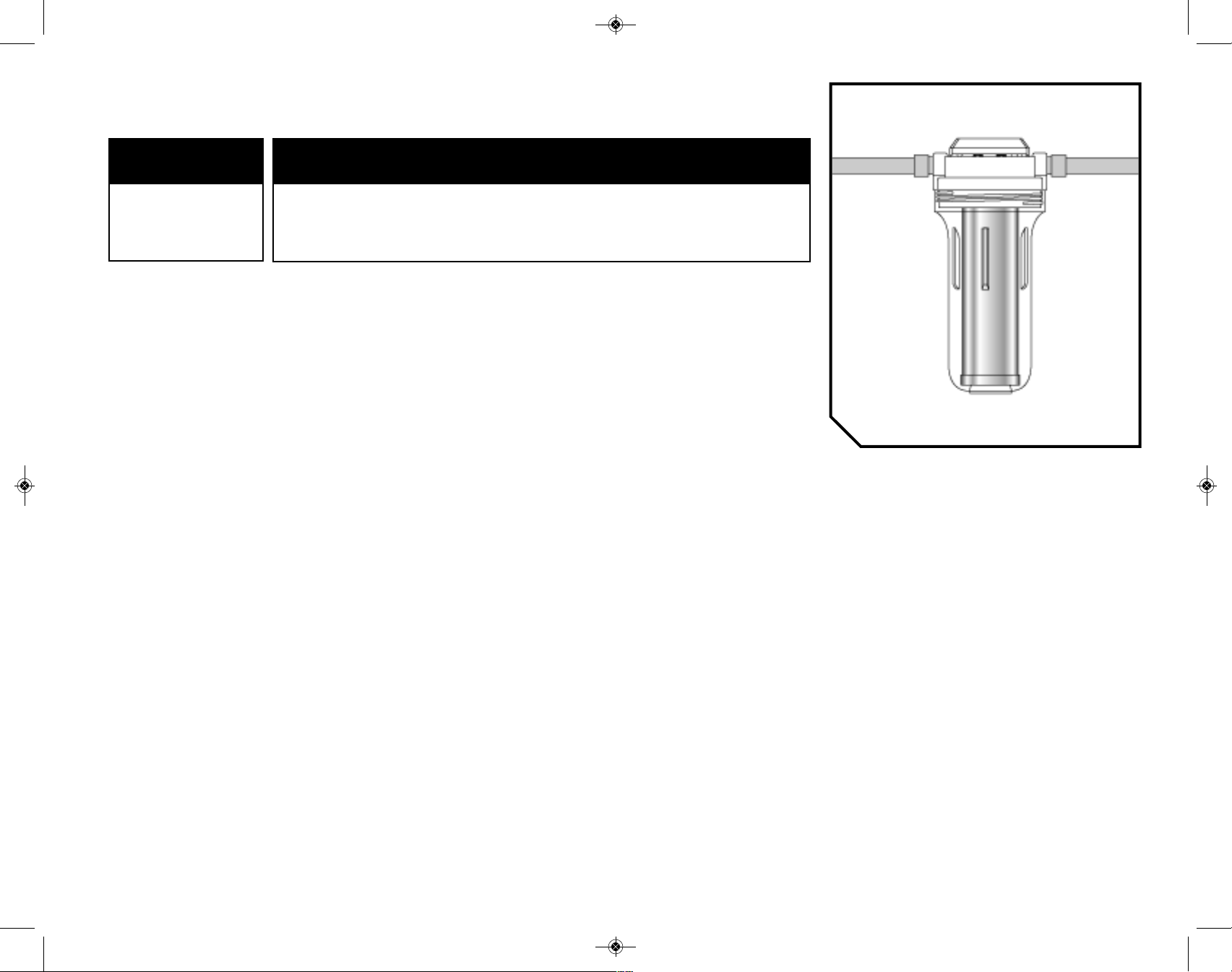
Operation/Maintenance Data
These filters are not water purifiers. Do not use with water that is microbiologically
unsafe or of unknown quality without adequate disinfection before or after the
system. Systems certified for Cyst reduction may be used on disinfected waters
that may contain filterable Cysts.
This unit is not designed to filter sulfur (rotten egg odor). Use of carbon filters to
treat sulfur may intensify taste/odor problems.
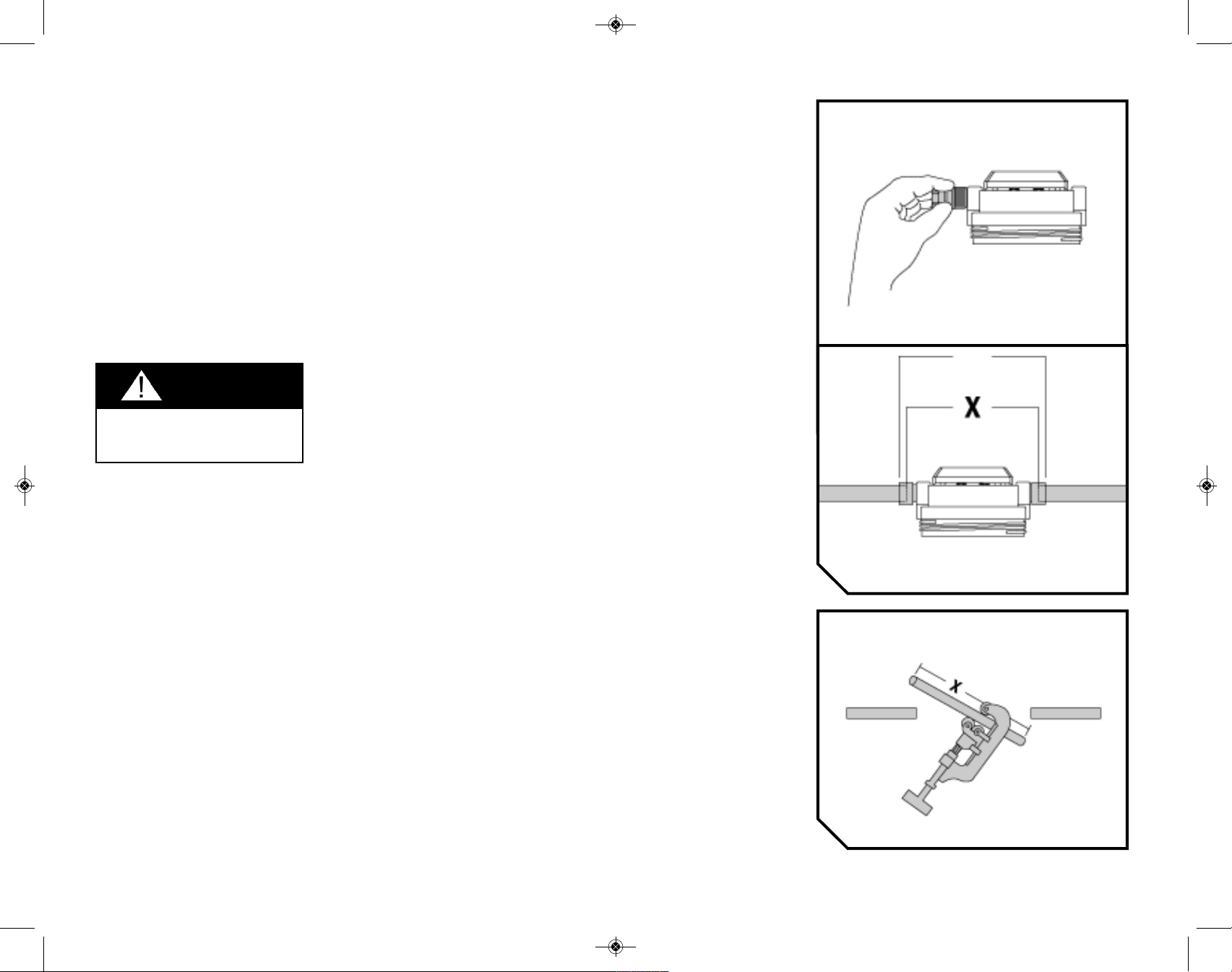
Please comply with all state and local regulations regarding the installation of
water treatment devices.
The contaminants or other substances reduced by the water filter device are not
necessarily in your water.
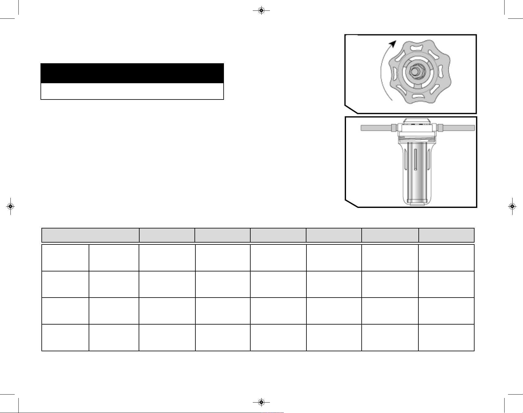
CAUTION
Usage and quality of water in your incoming water line affect the life of filter cartridges
and determine when the cartridge should be changed. Cartridges should be replaced
sooner if water pressure at the faucet begins to drop noticeably or if the filter fails to
perform satisfactorily.
Replacement Cartridges
DuPont™ Universal Valve-in-Head
Whole House Filtration Systems WFPF3800 and WFPF2800 Series
System Cartridge Model Numbers
________________________________________________________________________________________________
Universal Valve-in-Head WFPFC3002, WFPFC4002, WFPFC5002,
Whole House Filtration System WFPFC8002, WFPFC9002
WFPF2800 Series
________________________________________________________________________________________________
Universal Valve-in-Head WFPFC3002, WFPFC4002, WFPFC5002,
Whole House Filtration System WFPFC8002, WFPFC9002
WFPF3800 Series
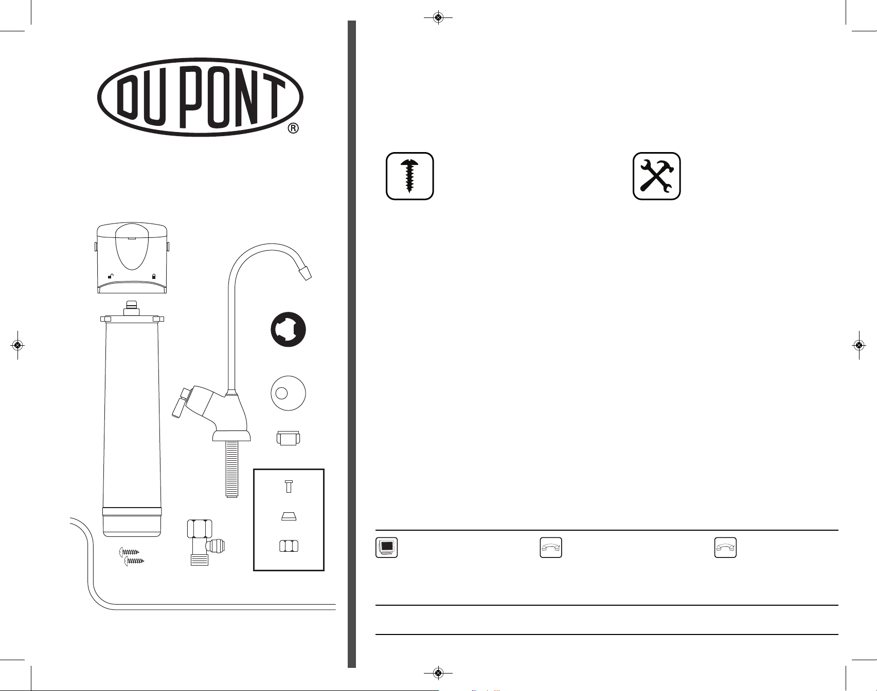
Replacement Parts
DuPont™ Universal Valve-in-Head
Whole House Filtration Systems WFPF3800 and WFPF2800 Series
Part Number Description
________________________________________________________________________________________________
WFAB150 Mounting Bracket
________________________________________________________________________________________________
WFAO150 O-Ring
________________________________________________________________________________________________
WFAW150 Filter Housing Wrench
________________________________________________________________________________________________
www.waterfiltration.DuPont.com
Protect Plus, LLC n Hickory, NC 28601 USA
866-709-2086 Gratis
For Service Requests & Product Information
Hours of Operation: 24 Hours/Day, 7 Days/Week
Ordering Information:
IM WFCH2 40 P :WFCH1_inst 8/13/09 1:47 PM Page 9