DUO-FAST DF150-CS User manual

IMPORTANT!
DO NOT DESTROY
It is the customer’s responsibility to have all
operators and service personnel read and
understand this manual.
OPERATING MANUAL AND
SCHEMATIC
511206-1
11/10
© 2010, Illinois Tool Works,Inc.
MODEL DF150-CS
Cap Stapler

2
INTRODUCTION
The DF150-CS cap stapler is a quality-built tool designed for use in residential
building applications. This tool will deliver efficient, dependable performance when used
according to the manufacturer’s guidelines. Please study this manual including the safety
instructions to fully understand the operation of this tool.
TOOL AND FASTENER SPECIFICATIONS ................................................................. 3
SAFETY INSTRUCTIONS ............................................................................................. 4
TOOL INSTALLATION AND OPERATION ................................................................ 5-8
FEATURES AND BENEFITS .......................................................................................... 9
EXPLODED VIEW AND SPARE PARTS LIST ....................................................... 10-11
MAINTENANCE ....................................................................................................... 12-13
TROUBLESHOOTING .................................................................................................. 14
WARRANTY .................................................................................................................. 15
ACCESSORIES ........................................................................................................... 16
Duo-Fast®

3
TOOL SPECIFICATIONS
MODEL NO. DF150-CS (Part# 511200)
HEIGHT 10 1/2”
WIDTH 4”
LENGTH 15 1/2"
WEIGHT 4 lbs. 8oz.
OPERATING PRESSURE 70 to 110 psi (4.8-7.6 bar)
FASTENER SPECIFICATIONS
TOOL AIR FITTINGS:
This tool uses a 1/4” N.P.T. male plug. The fitting must be capable of discharging tool
air pressure when disconnected from the air supply.
OPERATING AIR PRESSURE:
70 to110 psi (4.8 to 7.6 bar). Select the operating air pressure within this range
for best tool performance.
DO NOT EXCEED THIS RECOMMENDED OPERATING PRESSURE.
STAPLE RANGE 3/4”-1 1/2” (19-38mm)
STAPLE SIZE 18 Gauge, 3/8” Crown
TOOL AND FASTENER SPECIFICATIONS
STAPLE CAPACITY
CAP CAPACITY 240 Caps/Spool
90 Staples

4
WARNING
Failure to follow any of the above instructions could result in severe personal
injury to tool user and bystanders or cause damage to tool and property.
SAFETY INSTRUCTIONS
SAFETY FIRST
These safety instructions provide information necessary
for safe operation of Duo-Fast®tools. DO NOTATTEMPT
TO OPERATE THE TOOL UNTILYOU READ AND
UNDERSTAND ALL SAFETY PRECAUTIONS AND
MANUAL INSTRUCTIONS.
WEAR EYE AND HEARING PROTECTION
Always wear hearing and eye protection devices, that
conform to ANSI Z87.1 requirements, when operating
or working in the vicinity of a tool. As an employer you
are responsible for enforcing the use of eye protection.
Wear hard hats in environments that require their use.
THE TOOL MUST BE USED ONLY FOR THE PUR-
POSE FOR WHICH IT WAS DESIGNED
Do not throw the tool on the floor, strike the housing in
any way or use the tool as a hammer to knock
material into place.
NEVER ENGAGE IN HORSEPLAY WITH THE TOOL
The tool is not a toy so do not use it like one. Never
engage in horseplay with the tool or point it at yourself
or any other person, even if you think it is not loaded.
NEVER ASSUME THE TOOL IS EMPTY
Check the magazine for fasteners that may be left in the
tool. Even if you think the tool is empty or disconnected,
never point it at anyone or yourself. Unseen fasteners
could fire from the tool.
NEVER CLAMP THE TRIGGER IN A LOCKED OR
OPERATING POSITION
The trigger of the tool must never be tampered with,
disabled or clamped in a locked or operating position
since this will cause the tool to drive a fastener any
time the work contacting element is depressed.
DO NOT LOAD FASTENERS WITH THE AIR LINE
CONNECTED, OR WITH THE TOOL TRIGGER OR
WORK CONTACTING ELEMENT DEPRESSED
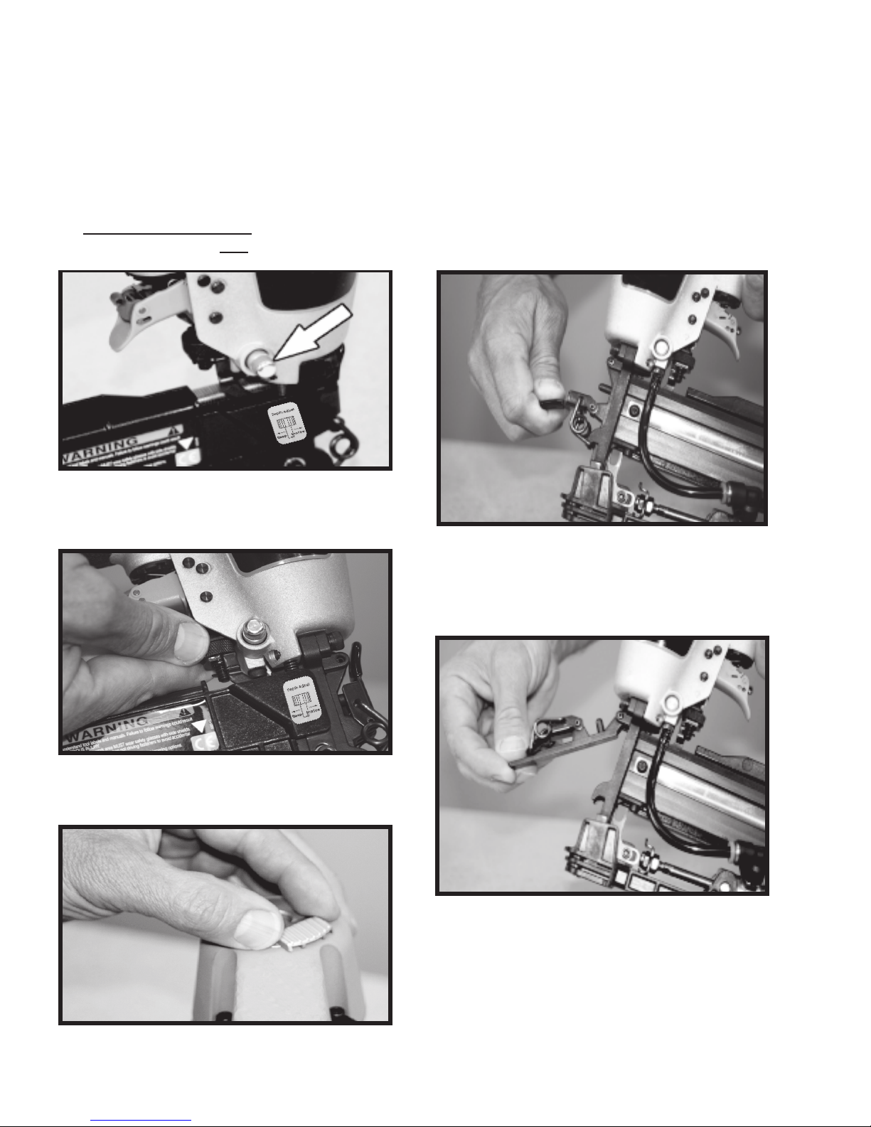
When loading fasteners into the tool be sure you
disconnect the air line and that you do not depress
the trigger or work contacting element.
OPERATE THE TOOL ONLY ON A WORKPIECE
The tool should be operated only when it is in contact
with the workpiece. Even then you should be careful
when fastening thin material or working near the edges
and corners of the workpiece since the fasteners may
drive through or away from the workpiece.
DO NOT DISABLE OR REMOVE THE WORK
CONTACTING ELEMENT
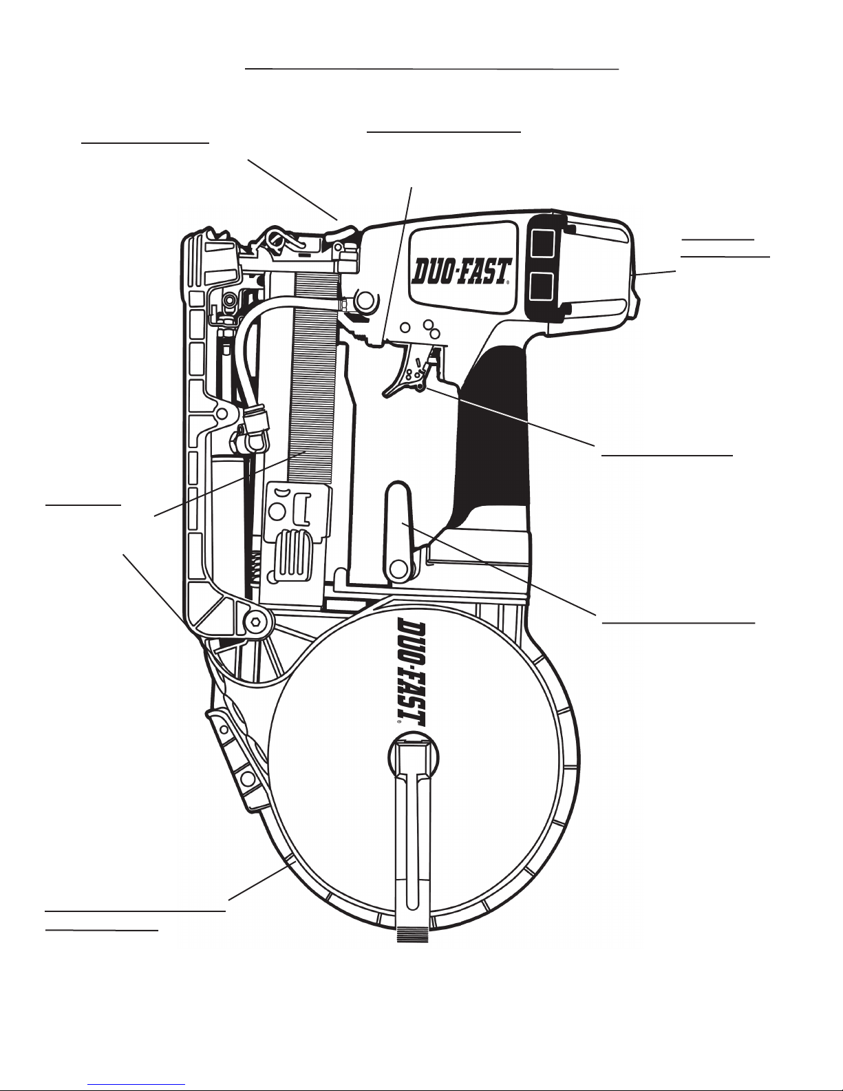
This tool is equipped with a safety mechanism, called
a work contacting element, to help prevent accidental
firing. Never tamper with, disable or remove the work
contacting element. Do not use the tool unless the
work contacting element is working properly. The tool
could fire unexpectedly.
DISCONNECT THE TOOL WHEN NOT IN USE
Always disconnect the tool from the air line when it
is not in use, when you leave the work area or when
moving the tool to a new location. The tool must
never be left unattended because people who are
not familiar with the tool might handle it and injure
themselves or others.
CARRY THE TOOL ONLY BY THE HANDLE
Always carry the tool by the handle only. Never carry
the tool by the air hose or with the trigger depressed
since you could drive a fastener unintentionally and
injure yourself or someone else.
DO NOT WEAKEN THE TOOL HOUSING
The tool housing is a pressure vessel and should never
be weakened by having your company’s name, area of
work or anything else stamped or engraved into its
surface.
DISCONNECT THE TOOL WHEN PERFORMING
REPAIRS AND CLEARING JAMS
Never attempt to clear a jam or repair a tool unless you
have disconnected the tool from the air line and
removed all remaining fasteners from the tool.
ALWAYS USE THE PROPER FITTING FOR THE
TOOL
Only MALE pneumatic type air connectors should be
fitted to the tool, so that high pressure air in the tool is
vented to atmosphere as soon as the air line is
disconnected.
NEVER install FEMALE quick disconnect couplings on
the tool. Female couplings will trap high pressure air in
the tool when the air line is disconnected, leaving the
tool charged and able to drive at least one fastener.
DO NOT EXCEEDTHE MAXIMUM RECOMMENDED
AIR PRESSURE
.erusserpriadednemmocerehttaylnolootehte
tarepO
Do not exceed the maximum air pressure marked on
the tool. Be sure the air pressure gauge is operating
properly and check it at least twice a day.
Never use any bottled air or gases such as oxygen to
operate the tool since they could cause the tool to
explode.
INSPECT TOOL FOR PROPER OPERATION
.deriuqersaetacirbuldnayliadtsaeltalootehtnaelC
Never operate a dirty or malfunctioning tool.
USE ONLY DUO-FAST RECOMMENDED PARTS AND
FASTENERS
Use only parts and fasteners specifically designed and
recommended by Duo-Fast®for use in the tool and for
work to be done. Using unauthorized parts and
fasteners or modifying the tool in any way creates
dangerous situations. Replace all missing warning
labels---refer to tool schematic for correct placement
and part number.

5
TOOL INSTALLATION
Your Duo-Fast®tool comes ready for immediate use
and can be installed by following these steps:
1. SAFETY - All tool operators and their immediate
supervisors must become familiar with the operator
safety instructions before operating the tool. The
instructions are on page 4 of this manual.
2. Included with each tool is a copy of this
manual and tool schematic.
Keep this publication for future reference. An
oownership registration card is also included.
This card must be completed and returned to
Duo-Fast®immediately to register your ownership.
3. The tool is shipped with a 1/4” male air fitting.
If you replace the air fitting, use only a male
pneumatic type that discharges the air from the
tool when the air line is disconnected.
4. Install a filter/regulator/lubricator unit, with a
gauge as close as practical to the tool, preferably
within ten feet. Refer to the Air Systems section of
this manual for air hose requirements and lengths.
In general, no other special installation is required.
5. If the operator is working at a bench or table,
it is usually best to run the air line underneath the
bench. A small tray under the benchtop can hold
the fastener supply and the tool when not in use.
6. If this tool does not work when it is first connect-
ed, do not try to make repairs. Call your Duo-Fast®
representative immediately.
Pneumatic System Maintenance
- Be certain that:
•Pneumatic fittings are tight and do not leak.
and ensure that automatic draining systems are
operating correctly.
• Air lines are cleared to prevent freezing,
especially in winter.
• Lubricator operation is checked regularly and
ensure it has an adequate supply of lubricant.
( Part No. 403720).
• Only regulated air is being used and that each
regulator is operating properly.
Tool Lubrication
It is most important that the tool be properly
lubricated by keeping the air line lubricator filled
and correctly adjusted. Without proper lubrica-
tion the tool will not work properly and parts will
wear prematurely.
Use the proper lubricant in the air line lubricator.
The lubricator should be of low air flow or
changing air flow type, and should be kept filled
to the correct level.
Use only Duo-Fast®recommended lubricants.
Substitutes may harm the rubber compounds in
the tools O-rings and other rubber parts. Part No.
403720 is a pneumatic lubricating oil specially
made for pneumatic applications.
If a filter/regulator/ lubricator is not installed on
the air system, air operated tools should be
lubricated at least once a day with 6-12 drops of
oil, depending on the work environment, directly
through the male fitting in the tool housing.

6
Loading of Staples
1. Pull the staple pusher back into the
locked position. Load a strip of staples onto
the rail.
2. Press the pusher release button and ease
the pusher forward until it engages with the
staples.
WARNING
Never load the tool with the trigger or work contact depressed.
TOOL OPERATION
1. Lift up the canister lever. (Remove the
empty spool.) Remove the tape from the
end of the cap strip.
Install the cap spool onto the canister
spindle with the end of the spool feeding
clockwise.
Loading of Caps
2. Slide the caps through the track to the
front of the nose. Close the canister lever
and snap it over the rim of the canister.

7
TOOL OPERATION -
continued
Triggering Selection
The tool is equipped with a trigger that can be switched
from sequential operation to bounce drive operation.
To switch the trigger, push the red lever inside the
trigger to the side and rotate it up or down until it locks
into the desired position.
The indicates that the tool is in the sequential position
and the indicates the tool is in the bounce drive
position.
Sequential Operation
The sequential trigger position prevents succesive or "bounce"
driving.
■ Depress the work contacting element and hold it against the
work surface before pulling the trigger.
■ After each fastener is driven, completely release the trigger
and lift the tool from the work surface.
Precision Placement Driving
■
Grasp the tool handle firmly and place the bottom of
the work contacting element firmly against the work-
■Squeeze the trigger to drive the fastener.
■ Lift the tool from the workpiece.
■ Repeat the procedure for the next fastener.
Successive (Bounce) Driving
■ Grasp the handle firmly.
■ Squeeze the trigger and move the tool along the workpiece
with a bouncing motion, depressing the work contacting element
at the points where you want to insert a fastener.
■ Keep the trigger depressed and continue to bounce the work
contacing element against the workpiece, positioning the tool
above as carefully as possible.
■ When the desired number of fasteners have been driven,
release the tool trigger to avoid unintentional fastener discharge.
Sequential
Drive Position
Successive (Bounce)
Drive Position
piece until it is completely depressed.

8
TOOL OPERATION -
continued
Staple Only Select Switch
The tool is equipped with a switch so it
will only drive staples.
To use this feature, position the switch so
the red bar on the switch is showing.
To feed caps and staples, push the switch
so that the red bar is not showing.
The depth of drive can be adjusted by rotating
the knurled wheel directly below the trigger.
Depth of Drive
Adjustable Air Deflector
The air deflector can be rotated so it will
exhaust the air away from the tool operator
Clearing a Jam
Should a jam occur, disconnect the air
supply and remove any remaining
staples from the tool.
Release the latch on the front of the nose
of the tool and lift up the front guide.
Remove the jammed fastener and close
the front guide and latch.

9
DF150-CS
FEATURES & BENEFITS
Directable
Exhaust Cap
Can be rotated to
direct exhaust away
from operator
AdjustableDepthofDrive
Provides precise control
of staple depth without adjusting
the compressor.
Versatility
Can drive staples
only,
or with caps.
Adjustable Belt Hook
Conveniently stowes the
tool.
Switchable Trigger
Switches from sequential to
bounce drive.
Easy to manuever with less arm
fatigue.
Balanced, Light weight,
In-Line Design
Quick Clear Nose
Easy access to clear jams.

1502576 1 Nyloc screw M4
2 502577 1 Washer 12*5*1
3 502578 1 Exhaust Cover
4 502579 1 O-Ring 8*2.5
5 502580 2 Cover, Grip
6 502581 2 Cap Guard
7 502582 4 Screw Set M4*25
8 502583 4 Screw M4*25
9 590042 4 Washer #4*1T
10 511205 1 Cap, Top
11 502585 1 O-Ring 15*2.5
12 502586 1 Seal, Air
13 502587 1 Gasket
14 502588 1 Spring
15 502589 1 Firing Valve Piston Set
16 502590 1 O-Ring 33.5*2.5
17 502591 1 Firing Valve Piston
18 502592 2 O-Ring 26.59*2.95
19 502593 1 Piston Stopper
20
502594 1 Piston Driver Assembly W/ O-Ring
21
502595 1 O-Ring 22.4*3.3
22
23
24
25
26
502600 1 Sleeve Retainer
27
502601 1 Cylinder Sleeve
28
502602 1 O-Ring 32*2.5
29
502603 1 Spacer
30
502604 1 O-Ring 44.8* 2.6
31
502605 1 Bumper
32
502606 1 Nozzle Washer
33
502607 1 Handle Grip
34
502608 1 Trigger Pin
35
502609 1 Body
36
502610 4 Pin Retainer ‘5.5*2
37
502611 1 Gasket
38
502612 1 Washer ‘12.5*1.6T
39
502613 1 Tail Cover
40
502614 1 Air Plug
PARTS LEGEND DF150-CS 511200
41
502615 1 Belt Hook
42
590055 1 Screw M5*20
43
502616 1 O-Ring 2.5*1.5 (Blue)
44
590043 1 Screw M4*8
45
502617 1 FW Air Plug
46
502618 1 Control Valve Rod Set
47
502619 1 Label
48
502620 2 O-Ring 5.8*1.9
49
502621 1 Control Valve Rod
50
502622 1 Support
51
502623 4 Screw M4*30
52
502624 1 Trigger Valve Set
53
502625 1 O-Ring 8*1.8
54
502626 1 Trigger Valve Head
55
502627 1 Spring
56
502628 2 O-Ring 2.6*1.2
57
502629 1 Trigger Valve Stem
58
502630 1 O-Ring 12.5*1.8
59
502631 1 Trigger Valve Guide
60
502632 1 O-Ring 14*1.8
61
502633 1 Trigger Set
62
502634 1 Extention Spring
502635 1 Releasing Blade
502636 1 Trigger Spring
65
502637 1 Trigger Guide
66
502638 1 Trigger
67
68
69
502641 1 Safety Adjustment Wheel
70
502642 1 Container Pin
71
502643 1 Spring
72
502644 1 Container
73
502645 1 Spacer
74
502646 1 Container Latch
75
502647 1 Pin ‘4*20
76
502648 1 Screw Set M5*22
77
590001 2 Screw M5*22
78
590002 2 Washer #5*1.2T
79
502649 1 Spacer
**
*
80
502650 1 Screw
81
502651 1 Spring 5.4*26.5L
82
502652 1 Release Catch
83
502653 1 E-Ring\ M+2A3704
84
502654 1 Magazine Cover
85
502655 1 Magazine Cover Spacer
86
502656 1 Spring
87
502657 1 Screww M4*28
88
590130 2 Nylon Nut M6
89
502658 1 Outlet Site Cover Set
90
502659 1 Stopper
91
502660 1 Spring Pin 3*28
92
502661 1 Outlet Site Cover
93
502662 1 Outlet Site Catch Assy.
94
502663 1 Outlet Site
95
502664 1 Magazine
96
590028 2 E-Ring ‘2.5
97
502665 1 Spring Set
98
502666 1 Nylock Screw M4*10
99
502667 1 B.H.C.S. M4*4
100
502668 1 Pusher
101
502669 1 Pusher Grip
102
502670 1 Compression Spring
103
502671 1 Lock Pin
104
502672 1 B.H.C.S. Screw M6*50
105
502673 4 Screw M4*10
106
502674 1 Pusher
107
502675 1 Cylinder Set
108
502676 1 Black Hose
109
502677 1 SPL601 Air Plug
110
502678
111
1 Nylon Nut M4
112
502679 1 Tray
113
502680 2 Wear Pad
114
502681 1 Nylock Screw M4*12
115
502682 1 F.H.C. Screw M3*12
116
117
118
590148 1 Hex Nut M6
119
502686 1 Spacer
120
502687 1 Spring
121
502688 1 Wheel
122
502689 1 Step Pin 3.5*16.3
123
502690 1 Pusher Set
511201 1 Housing Label, Left
511202 1 Housing Label, Right
511203 1 Model/ Warning Label
511204 2
*8
Name Plate
Denotes Normal Wear Item
Make sure Warning Label (511204 ) is properly affixed. Replace if Necessary. Label Available at no Charge through the Service Parts Dept.
Denotes New Change
➔
*
*
*
*
*
*
*
*
*
*
*
*
**
10
502692 1 Depth adjustment label
502693 1 Directional label
*
*
*
502683 1 Plate
63
64
502639 1 Pin
502640 1 Safety Guide Plate
*

11
DF150-CS
511200
123
1
2
121
29
22
24
23
25
26
27
28
30
31
32
33
32
35
36
34
37
38
39 40 41
42
43
44
45
46
47
48
49
50
51
52
53
54
55
56
57
58
59
60
52
61
62
63
64
65
66
67
68
69
70
71
72
73
74
75
76
103
77
78
79
80 81 82 83 84
85
86
87
88
89
90
91
92
93
94
95
96
97
98 99
100
101
102
104
105
106
107
108
109
110
112
111
113
114
115
116
117
118
119
120
122 92
84
101

12
MAINTENANCE
Duo-Fast
®tools are built for ease of maintenance. A few
simple details will assure trouble-free operation and long
tool life. Anyone who uses or maintains the tool must read
the safety and maintenance instructions. Study the sche-
matic drawing before starting any repairs on the tool.
Air-operated tools must be inspected periodically, and worn
or broken parts must be replaced to keep the tool operating
safely and efficiently. Also the items on the maintenance
chart must be checked often.
Cold Weather Care
When temperatures are below freezing, tools should be
kept warm by any convenient, safe method. If this is not
possible, the following procedure should be used to warm
up the tools.
❑ Reduce the regulated air pressure to 30 psi.
❑ Remove all fasteners from the tool.
❑ Connect an air line and blank fire the tool. The reduced
air pressure will be enough to free-fire the tool. Slow speed
operation tends to warm up the moving parts. Slowing up
the piston helps the bumper and the O-rings to become
springy.
❑ Once the tool is warmed up, readjust the regulator to the
proper working pressure and reload the tool.
❑ Tool operators working outdoors or in unheated areas in
extremely cold temperatures should also:
Use pneumatic oil with antifreeze in the
lubricator, Part No. 219090 (8oz.)
Once a week, depending on the amount of tool use,
take the tool apart and wash away any sludge with
tool cleaner (Part No. 219086) to keep the tool
operating efficiently.
Cleaning the air-operated tools with solvents removes the
thin coating of grease applied to the cylinder wall and
O-rings at the factory. To replace this coating of grease,
use Chemplex grease (Part No. 403734).
❑ Open the drain on the air compressor tank to drain any
moisture at least daily in extremely cold or humid weather.
A few ounces of anti-freeze in the tank will keep the air
free of frost.
Testing the Tool After Servicing
After replacing any part or parts, it is important to check
the tool for proper operation. This ensures that the tool
was put together correctly, is safe to use, and will perform
the job properly.
❑ Ensure that all hardware is tight.
❑ Ensure that the work contacting element is installed
correctly in relation to the trigger, and that both parts move
freely.
❑ Ensure that the magazine is properly attached.
❑ Ensure that the required safety information on the tool
is legible.
❑ Use only Duo-Fast®approved fasteners in the tool, and
ensure that they are correct for the application.
❑ Ensure that a male air fitting is securely connected to
the tool.
❑ Test the tool by driving fasteners into a workpiece iden-
tical to the tool's application.
❑ Check the tool for air leaks during testing and for the
proper sequence of operation.
❑ Ensure that all fasteners are driven to the same depth
and that the crown of the fastener is flush with the work-
piece.

13
MAINTENANCE - Continued
Drain air line filter(daily).
Keep lubricator filled.
Clean filter element-then blow
air through filter in direction
opposite to normal flow.
Check that all screws on tool
are tight.
Keep work contacting element
working properly.
Keep magazine and feeder
mechanism clean.
Lubricate "O" rings that are
replaced.
Use only Duo-Fast®replacement
parts.
ACTION WHY HOW
MAINTENANCE TABLE
Prevent accumulation of
mositure and dirt.
Keep tool lubricated.
Prevent clogging of filter with
dirt.
Prevent air leakage and pro-
mote efficient operation.
Promote operator safety and
efficient tool operation.
Prevent jamming of fasteners.
Assure long life and proper
operation of tool.
Keep tool operating efficiently
and maintain Duo-Fast®tool
warranty.
Open manual petcock (most
air supply systems have such
a valve).
Fill with pneumatic tool
lubricant. Part No.
403720.
Wash with soap and water or
follow manufacturers instruc-
tions.
Check screws daily.
Blow clean daily.
Blow clean daily.
Use Chemplex grease, Part
No. 403734.
Order any repacement parts
needed from Duo-Fast®Dealer.
CAUTION
Disconnect the tool when performing
repairs or clearing jams.

14
OPERATOR TROUBLESHOOTING
PROBLEM CORRECTIVE ACTION
Fasteners will not drive completely into wood.
Fasteners penetrate properly during normal
operation, but won't drive fully at faster speeds.
Fasteners drive too deeply into wood.
Tools skips during operation - no fasteners are
driven from time to time.
Tool operates, but no fasteners are driven.
Air leaks when tool is connected to air.
Adjust work contacting element (retract length).
Increase air pressure (do not exceed 120 psi).
Increase air flow to tool -- use larger air lines.
Adjust work contacting element (extend length).
Reduce air pressure.
Check magazine for proper fasteners. Magazine fol-
lower should slide freely. Clean as needed to remove
debris.
Make sure correct fasteners are being used.
Use fasteners that meet Duo-Fast®
specifications
Increase air flow to tool -- use larger air lines.
Adjust work contacting element.
Check magazine for proper fasteners. Fasteners
should slide freely with no follower pressure.
Increase air pressure (do not exceed 120psi).
Tighten screws and fittings.
No cap feed.
Check Cap feed switch to make sure it is in the cap
feed position.
Cap chain may be broken in track. Thread caps from
canister to pusher.
14
CAUTION
Disconnect the tool when performing
repairs or clearing jams.
only.

15
An Illinois Tool Works Company
955 National Parkway
Schaumburg, Illinois 60173-5172
TOOL WARRANTY AND LIMITATIONS
TOOL WARRANTY
Duo-Fast warrants that newly purchased power
fastening tools, parts and accessories will be free
from defects in material and workmanship for the
period shown below, after the date of delivery to
the original user.
90-DAY LIMITED WARRANTY
A 90-day warranty will apply to all parts, except
those which are specifically covered by an extended
warranty.
EXTENDED LIMITED WARRANTY FOR ON SITE
CONSTRUCTION APPLICATIONS
assembly castings. A six month warranty will apply
to all magazine parts.
NORMAL WEARING PARTS
The following parts are considered normal wearing
parts and are not under warranty.
• Bumper
• Driver Blades
• ”O” Rings
• Piston Rings
WARRANTY STATEMENT
Thiswarrantyislimitedtotoolssoldandservicerequested
in the United States. To obtain information on warranty
service in the United States, refer to the Service Center
listing that was provided with your tool.
Duo-Fast's sole liability hereunder will be to replace any part
or accessory which proves to be defective within the specific
time period. Any replacement part or accessory provided in
accordance with this warranty will carry a warranty for the
balance of the period of warranty applicable to the part it
replaces. This warranty does not apply to part replacement
required due to normal wear.
This warranty is void as to any tool which has been subjected
to misuse, abuse, accidental or intentional damage, use with
fasteners,fuel, batteries, or batterychargersnotmeetingDuo-
Fast
®
specification, size, or quality, improperly maintained,
repairedwith other than genuine Duo-Fast replacementparts,
damagedintransitor handling,orwhich,inDuo-Fast'sopinion,
has been altered or repaired in a way that affects or detracts
from the performance of the tool.
DUO-FAST MAKES NO WARRANTY,EXPRESSED OR
IMPLIED, RELATING TO MERCHANTABILITY, FITNESS,
OR OTHERWISE, EXCEPT AS STATED ABOVE, and DUO-
FAST's liability AS STATED ABOVE AND AS ASSUMED
ABOVE is in lieu of all other warranties arising out of, or
in connection with, the use and performance of the tool,
except to the extent other wise provided by applicable law.
DUO-FAST
SHALL IN NO EVENT BE LIABLE FOR ANY
DIRECT, INDIRECT, OR CONSEQUENTIAL DAMAGES,
INCLUDING, BUT NOT LIMITED TO, DAMAGES WHICH
MAY ARISE FROM LOSS OF ANTICIPATED PROFITS OR
PRODUCTION, SPOILAGE OF MATERIALS, INCREASED
COST OF OPERATION, OR OTHERWISE.
A one year warranty will apply to all housing and cap
®
®
®
®

Lubricants and Loctite
Loctite 242 (Blue) Part No. 093500
Lubricating Oil 16 oz. Part No. 403720
Lubricating Oil with Antifreeze 8 oz. Part No. 219090
Chemplex 710 Lubricant 1lb. Part No. 403734
Tool Cleaner
Ideal cleaner for all Duo-Fast®tools. Part No. 219348
Safety Glasses
Clear Part No. 401382
ACCESSORIES
Part No. 502694
An Illinois Tool Works Company
955 National Parkway
Schaumburg, Illinois 60173-5172
Tool Case
Table of contents
Other DUO-FAST Power Tools manuals
Popular Power Tools manuals by other brands

Atlas Copco
Atlas Copco QST42-50CT-T50-L134-H13 Product instructions

jcb
jcb 21-18BLID Instructions & user's manual

Wacker Neuson
Wacker Neuson PV 35A Operator's manual

Greencut
Greencut GM650X Series instruction manual

Baileigh Industrial
Baileigh Industrial DP-1000VS Operator's manual

Porter-Cable
Porter-Cable 643 instruction manual

Graco
Graco 244766 Instructions-parts list

Weber mt
Weber mt SRV 620 Operating and maintenance manual

Bostitch
Bostitch TU-216-2330K-E Original instructions

Black & Decker
Black & Decker 1VPX instruction manual

Wacker Neuson
Wacker Neuson DPU 25 Series Operator's manual

HIKOKI
HIKOKI M 8V2 Handling instructions