Duralloy TIG 191P AC/DC User manual

.
TIG 191P AC/DC
OWNER’S MANUAL
www.duralloy.net.au | 1300 369 456

CONTENT
1 SAFETY....................................................................................................................................................1
1.1 SIGNAL EXPLANATION..........................................................................................................................1
1.2 ARC WELDING DANGERS.................................................................................................................... 1
1.3 THE KNOWLEDGE OF ELECTRIC AND MAGNETIC FIELDS......................................................................5
2 SUMMARY.............................................................................................................................................6
2.1 BRIEF INTRODUCTION........................................................................................................................ 6
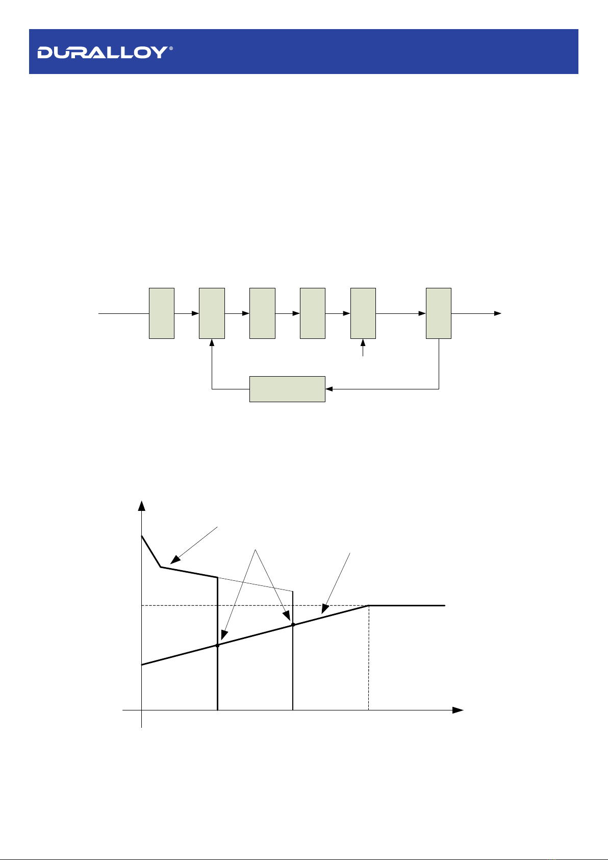
2.2 WORKING PRINCIPLE.........................................................................................................................8
2.3 VOLT-AMPERE CHARACTERISTIC....................................................................................................... 8
3 INSTALLATION AND ADJUSTMENT..................................................................................................9
3.1 PARAMETERS..................................................................................................................................... 9
3.2 DUTY CYCLE & OVER HEAT.............................................................................................................10
3.3 MOVEMENT AND PLACEMENT...........................................................................................................10
3.4 POWER SUPPLY INPUT CONNECTION................................................................................................. 11
3.5 POLARITY CONNECTION(MMA).................................................................................................. 11
3.6 ASSEMBLING THE EQUIPMENT (TIG).................................................................................................12
4 OPERATION......................................................................................................................................... 13
4.1 LAYOUT FOR THE PANEL...................................................................................................................13
4.2 CONTROL PANEL.............................................................................................................................. 14
4.4 ARGON ARC WELDING OPERATION................................................................................................. 18
4.4.1 TIG welding (4T operation)
...................................................................................................
18
4.4.2 TIG welding (2T operation)
.................................................................................................
19
4.5 WELDING PARAMETERS................................................................................................................... 21
4.5.1 Joint forms in TIG/MMA
........................................................................................................
21
4.5.2 The explanation of welding quality
....................................................................................
21
4.5.3 TIG Parameters Matching
....................................................................................................
21
4.6 OPERATION ENVIRONMENT.............................................................................................................24
4.7 OPERATION NOTICES......................................................................................................................24
5 MAINTENANCE & TROUBLESHOOTING........................................................................................25
5.1 MAINTENANCE.................................................................................................................................25
5.2 TROUBLESHOOTING........................................................................................................................26
5.3 ELECTRICAL PRINCIPLE DRAWING.....................................................................................................29
6 EXPLODED VIEW DRAWING............................................................................................................ 30
TIG191P AC/DC OWNER’S MANUAL
www.duralloy.net.au | 1300 369 456

1
1 .SAFETY
1.1 Signal Explanation.
The above signals mean warning! Notice! Running parts and getting an electric shock or
thermal parts will take damage for your body or others. The corresponding notices are as
follows. It is quite a safe operation after taking several necessary protection measures.
1.2 Arc Welding dangers.
The following signals and word explanations are some dangers for your body or others near
the welding operation. While seeing these, please remind of yourself this operation can be
dangerous.
Only ones who are trained professionally can install, debug, operate, maintain, and repair the
equipment.
During the operation no other people should be present.
After turning off the machine power, please maintain and examine the equipment according
to (5) because of the DC voltage existing in the electrolytic capacitors.
ELECTRIC SHOCK CAN KILL.
Never touch electrical parts.
Wear dry, hole-free gloves and clothes to insulate yourself.
Insulate yourself from work and ground using dry insulation. Make certain the insulation is
large enough to cover your full area of physical contact with work and ground.
Take care when using the equipment in a small space, uneven surface, and wet areas.
Never turn on the machine power before installation and adjustment.
Ensure to install the equipment correctly and ground the work or metal to be welded to a
good electrical (earth) ground according to the operation manual.
The electrode and work (or ground) circuits are electrically “hot” when the welder is on. Do
not touch these “hot” parts with your bare skin or wet clothing. Wear dry, hole-free gloves to
insulate hands.
TIG191P AC/DC OWNER’S MANUAL
www.duralloy.net.au | 1300 369 456

2
In semiautomatic or automatic wire welding, the electrode, electrode reel, welding head,
nozzle or semiautomatic welding gun are also electrically “hot”.
Always be sure the work cable makes a good electrical connection with the metal being
welded. The connection should be as close as possible to the area being welded.
Maintain the electrode holder, work clamp, welding cable and welding machine in good, safe
operating condition. Replace damaged insulation.
Never dip the electrode in water for cooling.
Never simultaneously touch electrically “hot” parts of electrode holders connected to two
welders because voltage between the two can be the total of the open circuit voltage of both
welders.
When working above floor level, use a safety belt to protect yourself from a fall should you
get a shock.
FUMES AND GASES CAN BE DANGEROUS.
Welding may produce fumes and gases hazardous to health. Avoid breathing these fumes
and gases. When welding, keep your head out of the fume. Use enough ventilation and/or
exhaust at the arc to keep fumes and gases away from the breathing zone. When welding with
electrodes which require special ventilation such as stainless or hard facing or on lead or
cadmium plated steel and other metals or coatings which produce highly toxic fumes, keep
exposure as low as possible and below Threshold Limit Values using local exhaust or
mechanical ventilation. In confined spaces or in some circumstances, outdoors, a respirator may
be required. Additional precautions are also required when welding on galvanized steel.
Do not weld in locations near chlorinated hydrocarbon vapors coming from degreasing,
cleaning or spraying operations. The heat and rays of the arc can react with solvent vapors to
form phosgene, a highly toxic gas, and other irritating products.
Shielding gases used for arc welding can displace air and cause injury or death. Always use
enough ventilation, especially in confined areas, to ensure breathing air is safe.
Read and understand the manufacturer’s instructions for this equipment and the
consumables to be used, including the material safety data sheet and follow your employer’s
safety practices.
TIG191P AC/DC OWNER’S MANUAL
www.duralloy.net.au | 1300 369 456

3
ARC RAYS CAN BURN.
Use a shield with the proper filter and cover plates to protect your eyes from sparks and the
rays of the arc when welding or observing open arc welding.
Use suitable clothing made from durable flame-resistant material to protect your skin and
that of your helpers from the arc rays.
Protect other nearby personnel with suitable, non-flammable screening and /or warn them
not to watch the arc nor expose themselves to the arc rays or to hot spatter or metal.
SELF-PROTECTION.
Keep all equipment safety guards, covers and devices in position and in good repair. Keep
hands, hair, clothing and tools away from V-belts, gears, fans and all other moving parts when
starting, operating or repairing equipment.
Do not put your hands near the engine fan. Do not attempt to override the governor or idler
by pushing on the throttle control rods while the engine is running.
DO NOT adds the fuel near an open flame welding arc or when the
engine is running. Stop the engine and allow it to cool before refueling to prevent spilled fuel
from vaporizing on contact with hot engine parts and igniting. Do not spill fuel when filling tank.
If fuel is spilled, wipe it up and do not start engine until fumes have been eliminated.
WELDING SPARKS can cause fire or explosion.
Remove fire hazards from the welding area. If this is not possible, cover them to prevent the
welding sparks from starting a fire. Remember that welding sparks and hot materials from
welding can easily go through small cracks and openings to adjacent areas. Avoid welding near
hydraulic lines. Have a fire extinguisher readily available.
Where compressed gases are to be used at the job site, special precautions should be used
to prevent hazardous situation.
When not welding, make certain no part of the electrode circuit is touching the work or
TIG191P AC/DC OWNER’S MANUAL
www.duralloy.net.au | 1300 369 456

4
ground. Accidental contact can cause overheating and create a fire hazard.
Do not heat, cut or weld tanks, drums or containers until the proper steps have been taken to
ensure that such procedures will not cause flammable or toxic vapors from substances inside.
They can cause an explosion even though they have been “cleaned”.
Vent hollow castings or containers before heating, cutting, or welding. They may explode.
Sparks and spatter are thrown from the welding arc. Wear oil free protective garments such
as leather gloves, heavy shirt, cuff less trousers, safety boots and welding hood. Wear ear plugs
when welding out of position or in confined places. Always wear safety glasses with side shields
when in a welding area.
Connect the work cable to the work as close to the welding area as practical. Work cables
connected to the building framework or other locations away from the welding area increase
the possibility of the welding current passing through lifting chains, crane cables or other
alternate circuits. This can create fire hazards or overheat lifting chains or cables until they fail.
Rotating parts may be dangerous.
Use only compressed gas cylinders containing the correct shielding gas for the process used
and properly operating regulators designed for the gas and pressure used. All hoses, fittings,
etc. should be suitable for the application and maintained in good condition.
Always keep cylinders in an upright position securely chained to an undercarriage or fixed
support.
Cylinders should be located:
-Away from areas where they may be struck or subjected to physical damage.
-A safe distance from arc welding or cutting operations and any other source of heat,
sparks, or flame.
Never allow the electrode, electrode holder or any other electrically “hot” parts to touch a
cylinder.
Keep your head and face away from the cylinder valve outlet when opening the cylinder
valve.
Valve protection caps should always be in place and hand tight except when the cylinder is
in use or connected for use.
TIG191P AC/DC OWNER’S MANUAL
www.duralloy.net.au | 1300 369 456

5
1.3 The knowledge of Electric and Magnetic Fields.
Electric current flowing through any conductor causes localized Electric and Magnetic Fields
(EMF). The discuss on the effect of EMF is ongoing all the world. Up to now, no material
evidence shows that EMF may have effects on health. However, the research on damage of
EMF is still ongoing. Before any conclusion, we should minimize exposure to EMF as few as
possible.
To minimize EMF, we should use the following procedures:
Route the electrode and work cables together – Secure them with tape when possible.
All cables should be put away and far from the operator.
Never coil the power cable around your body.
Make sure welding machine and power cable to be far away from the operator as far as
possible according to the actual circumstance.
Connect the work cable to the workpiece as close as possible to the area being welded.
The people with heart-pacemaker should be away from the welding area.
TIG191P AC/DC OWNER’S MANUAL
www.duralloy.net.au | 1300 369 456

6
2.SUMMARY
2.1 Brief Introduction.
TIG-191PACDC welding machine adopts the latest pulse width modulation (PWM)
technology and insulated gate bipolar transistor (IGBT) power module, which can change
work frequency to medium frequency to replace the traditional large transformer style
machine. Thus, it is characterized with portable, small size, light weight, low power
consumption etc.
The parameters of TIG-191PACDC on the front panel all can be adjusted continuously, such
as start current, crater arc current, welding current, base current, duty ratio, up-slope time,
down-slope time, pre-gas, post-gas, pulse frequency, AC frequency, balance, hot start, arc
force and arc length etc. When welding, it takes high frequency and high voltage for arc
ignition to ensure the success ratio of initiating the arc.
TIG-191PACDC Characteristics:
MCU control system responds immediately to any changes.
High frequency and high voltage for arc igniting to ensure the success ratio of igniting
the arc, the reverse polarity ignition ensures good ignition behavior in TIG-AC
welding.
Avoid AC arc-break with special means, even if arc-break occurs the HF will keep the
arc stable.
Pedal foot control of the welding current. (optional)
TIG/DC operation, If the tungsten electrode touches the work piece when welding,
the current will drop to short-circuit current to protect tungsten.
Intelligent protection: over-voltage, over-current, over-heat, when the problems listed
before occurring, the alarm lamp on the front panel will be on and the output current
will be cut off. It can self-protect and prolong the equipment lifespan.
Double purposes: AC inverter TIG and DC inverter TIG/MMA, Excellent performance
on Al-alloy、carbon steel、stainless steel、titanium.
According to choosing the front panel functions, the following five welding processes
can be used.
TIG191P AC/DC OWNER’S MANUAL
www.duralloy.net.au | 1300 369 456

7
DC MMA
DC TIG
DC Pulse TIG
AC TIG
AC Pulse TIG
1.For DC MMA, polarity connection can be chosen according to different electrodes,
please refer to (3.5).
2.For DC TIG, DCEP is used normally (work piece connected to positive polarity, while
torch connected to negative polarity). This connection has many characters, such as
stable welding arc, low tungsten consumption, more welding current, narrow and deep
weld.
3.For AC TIG (square wave), arc is more stable than Sine AC TIG. At the same time,
you can not only obtain the max penetration and the min tungsten consumption, but
also obtain a better cleaning effect.
4.DC Pulsed TIG has the following characters: 1) Pulse heating. Metal in Molten pool
has short time on high temperature status and freezes quickly, which can reduce the
possibility to produce hot crack of the materials with thermal sensitivity. 2) The work
piece gets little heat. Arc energy is focused. Is suitable for thin sheet and super thin
sheet welding. 3) Exact control heat input and the size of the molten pool. The depth of
penetration is even. Is suitable for welding by one side and forming by two sides and
all position welding for pipe. 4) High frequency arc can make metal for microlite fabric,
eliminate porosity, and improve the mechanical performance of the joint. 5) High
frequency arc is suitable for high welding speed to improve productivity.
TIG-191P series welding machine is suitable for all positions welding for various plates
made of stainless steel, carbon steel, alloyed steel, titanium, aluminium.
MMA——Manual Metal Arc welding.
PWM——Pulse-Width Modulation.
IGBT——Insulation Gate Bipolar Transistor.
TIG——Tungsten Insert Gas welding.
TIG191P AC/DC OWNER’S MANUAL
www.duralloy.net.au | 1300 369 456

8
2.2 Working Principle.
The working principle of TIG191P welding machines is shown as the following figure.
Single-phase 220V work frequency AC is rectified into DC (about 312V), then is converted
to medium frequency AC (about 50KHz) by inverter device (IGBT module), after reducing
voltage by medium transformer (the main transformer) and rectifying by medium frequency
rectifier (fast recovery diodes), then is outputted DC or AC by selecting IGBT module. The
circuit adopts current feedback control technology to insure current output stably.
Meanwhile, the welding current parameter can be adjusted continuously to meet with the
requirements of the process.
Rectif
ier
Invert
er
Trans
forme
r
Rectif
ier
Hall
devic
e
Current feedback
control
Single-phase, AC DC AC DC
220V,50Hz
AC Invert
er
AC or DC
Control signal
AC or DC
2.3 Volt-Ampere Characteristic.
TIG-191PACDC welding machine has an excellent volt-ampere characteristic, whose graph
is shown as the following figure. The relation between the conventional rated loading
voltage U2 and the conventional welding current I2 is as follows:
67
34
10
0 600 I2(A)
U2(V)
Working
point
Volt-ampere characteristic The relation between the
conventional loading
voltage and welding current
When I2≤600A,U2=10+0.04I2(V); When I2>600A,U2=34(V).
TIG191P AC/DC OWNER’S MANUAL
www.duralloy.net.au | 1300 369 456

9
3.Installation and Adjustment
3.1 Parameters
Models
Parameters
TIG-191P AC/DC
Input power
1~240±10%,50Hz
Rated input current(A)
37(TIG)
44(MMA)
Rated input power
(KVA)
8.2(TIG)
9.6(MMA)
Power factor
0.73
Max no-load voltage(V)
78
Adjustment range of
start current(A)
TIG
MMA
AC
DC
DC
HF
LIFT
10~welding
current
—
10~welding
current
30~welding
current
Adjustment range of
welding current(A)
10~200
30~200
10~200
10~180
Adjustment range of
Crater arc current(A)
10~200
30~200
10~200
10~180
Adjustment range of
downslope time(S)
0~5
Pre-gas time(S)
0.1~1
Adjustment range of
post-gas time(S)
0.1~10
Clearance effect(%)
20~50
Efficiency
Duty cycle
AC
DC
10% 200A
10% 180A
60% 82A
60% 73A
100% 63A
100% 57A
Protection class
IP21S
Insulation class
H
Dimensions of Machine
(L×W×H)(mm)
475X185X325
Weight (Kg)
8
TIG191P AC/DC OWNER’S MANUAL
www.duralloy.net.au | 1300 369 456

10
3.2 Duty cycle & Overheat.
The letter “X” stands for duty cycle, which is defined as the proportion of the time that a
machine can work continuously within a certain time (10 minutes). The rated duty cycle
means the proportion of the time that a
machine can work continuously within 10
minutes when it outputs the rated
welding current.
The relation between the duty cycle “X”
and the output welding current “I” is
shown as the right figure.
If the welder is over-heat, the IGBT
over-heat protection unit inside it will output an instruction to cut output welding current
and illuminate the over-heat pilot lamp on the front panel. At this time, the machine should
be rested for 15 minutes to cool. When operating the machine again, the welding output
current or the duty cycle should be reduced.
3.3 Movement and placement.
Please take care of the welder when moving it.
It also can be carried by the handle on the top of the welder. Place the welder in the right
position. When the machine gets to the destination, it needs to be placed on a flat surface.
Any movement may result in the potential danger or substantive hazard, so please make
sure that the machine is on the safe position before using it.
I(A)
0
100%
25%
100 200
XThe relation of the welding current and
duty cycle for WSME-200
TIG191P AC/DC OWNER’S MANUAL
www.duralloy.net.au | 1300 369 456

11
3.4 Power supply input connection.
TIG-191P welding machines’ power supply connects to 240V 10a.
When the power supply voltage is over the safe work voltage, there are over voltage and
under voltage protection inside the welder, the alarm light will illuminate, at the same time,
the current output will be shut off.
If the power supply voltage continually goes beyond the safe work voltage range, it will
decrease the welder’s lifespan. The below measures can be used:
Ensure the machine is plugged into a 240v 10amp supply.
3.5 Polarity Connection(MMA).
MMA (DC): Choosing the connection of DCEN or DCEP according to the different
electrodes. Please refer to the electrode manual.
MMA: requirements for polarity connection.
TIG191P AC/DC OWNER’S MANUAL
www.duralloy.net.au | 1300 369 456

12
3.6 Assembling the equipment (TIG)
Workpiece is connected to the positive electrode of welding machine, and welding
torch is connected to the negative electrode, which is called DC POSITIVE
CONNECTION; otherwise, that is called DC NEGATIVE CONNECTION. Generally, it is
usually operated in DC POSITIVE CONNECTION in TIG welding mode.
The control cable of torch switch consists of 2 wires, pedal control of 3 wires and the
aero socket is 5 pin.
Consumable parts for TIG torch, such as tungsten electrode, gas nozzle electrode
etc , please email or phone according to the accessory codes.
When AC/DC welding machines are operated in HF ignition method, the ignition spark
can cause interferences in equipment near the welding machine. Be sure to take
specially safety precautions or shielding measures.
TIG191P AC/DC OWNER’S MANUAL
www.duralloy.net.au | 1300 369 456

13
4 .Operation
4.1 Layout for the panel
1Aviation socket connected to torch switch control wire.
2Negative output welder’s negative ( - ) polarity output.
3Shield gas connector Is connected to the gas input hose of the torch.
4Positive output welder’s positive ( + ) polarity output.
5Power source switch Switch to “ON”, the welder is turned on, while switch to “OFF”, the
welder is turned off.
6Power source input connect power source.
7Shield gas input connect the gas hose while the other end is connected to argon
regulator & gas cylinder.
1
2
3
4
7
5
6
TIG191P AC/DC OWNER’S MANUAL
www.duralloy.net.au | 1300 369 456

14
(5)Selection & Adjustments key (Press)
4.2 Control panel
(3) AC/DC selecting key
(2) Mode selecting key
(4)2T/4T Selection
(1) Display
(6) Arc force/Hot start
TIG191P AC/DC OWNER’S MANUAL
www.duralloy.net.au | 1300 369 456

15
Overview.
The key feature of the control panel is the logical way in which the controls are arranged. All the main
parameters needed for day-to-day working.
-selected with the keys
-altered with the adjusting dial
-shown on the display during welding.
The illustration below shows an overview of the main settings needed for day-to-day use, using the
TIG-191P control panel as an example. You will find a detailed description of these settings in the following
section.
(1) AC/DC selection key
AC welding
DC welding
(2) Mode selection key
2-step mode
4-step mode
(3.1) HF TIG
(3.2) LIFT TIG
(3.3) MMA Mode
(3.4) Gas-test key
(4) Parameter selection keys (Press to adjust)
(8) Adjusting dial
If the parameter indicator lights up, then the selected parameter can be altered on adjusting dial.
Available parameters where 2T and 4T mode have been selected:
TIG191P AC/DC OWNER’S MANUAL
www.duralloy.net.au | 1300 369 456

16
Pre-flow time
Unit S
Setting range 0.1—1
Factory setting 0.3
Start (starting only with 4T)
Unit A
Setting range 10—100%of main current Iw (DC);10—100%of main current Iw (AC-HF)
10—100%of main current Iw (AC-LIFT)
Factory setting 5
Upslope time
Unit S
Setting range 0—5
Factory setting 0
IMMA/ITIG: Welding current
Unit A
TIG-200 10—200 (TIG-DC) ;10—200 (TIG-AC-HF);10—200 (TIG-AC-LIFT);
10—180 (MMA-DC) ;
Base: Base current
Unit A
TIG-200 10—200 (DC);10—200 (AC-HF) ;10—200 (AC-LIFT)
Important! Only selectable when “pulse key” has been pressed.
Suggestion! Ib and Iw cannot differ greatly.
Width Ratio of pulse duration to base current duration.
Unit %
Setting range 5—100
Factory setting 5
Important! Only selectable when “pulse key” has been pressed.
Hz: Pulse frequency
Unit Hz
Setting range 0.5—200
Factory setting 0.5
Important! Only selectable when “pulse key” has been pressed.
D slope : Downslope time
Unit S
Setting range 0—5
Factory setting 0
TIG191P AC/DC OWNER’S MANUAL
www.duralloy.net.au | 1300 369 456

17
Stop: Crater arc current (only with 4T)
Unit S
Setting range 10—100% of main current Iw (DC);10—100% of main current Iw (AC-HF)
10—100% of main current Iw (AC-LIFT)
Factory setting 5
Post-flow
Unit S
Setting range 0.1—10
Factory setting 3
Hz: AC frequency (only with TIG-AC)
Unit Hz
Setting range 40—200
Balance (only with TIG-AC)
Balance adjustment is mainly used to set the adjustment of eliminating metal-oxide (such as Aluminium,
Magnesium and its alloy) while AC output.
Unit %
Setting range 20—50
Factory setting 20
(9) Electrode (MMA) welding key
Parameter Setting range
Arc force 0-10
Hot start 0-10
.
(11) Welding voltage/other parameter display
Indicate the welding voltage or other parameter.
Before the start of welding, the right-hand display shows the pre-set value of Tpr, Tup, Dcy, Fp, Tdown andTpo.
There is a 3s time-lag, open-circuit voltage is displayed after adjusting those parameters.
After the start of welding, the right-hand display shows the present actual value of the welding voltage.
(12) Welding current display
Display the pre-set or the actual welding current value.
Before the start of welding, the left-hand display shows the pre-set current value of Is, Iw, Ib and Ic.
After the start of welding, the left-hand display shows the present actual value of the welding current.
The control panel indicates which position has been reached in the welding process by brightening the light.
NOTE:
Only “Parameter selection keys” and “Adjusting dial” can be used in the welding process.
Only “Rod electrode welding key”, “Adjusting dial” and “AC/DC selecting key” can be used on MMA mode.
TIG191P AC/DC OWNER’S MANUAL
www.duralloy.net.au | 1300 369 456

18
4.4 TIG Welding Operation
4.4.1 TIG welding (4T operation)
The start current and crater current can be pre-set. This function can compensate the possible crater
that appears at the beginning and end of the welding. Thus, 4T is suitable for the welding of medium
thickness
plates.
Introduction :
0:Press and hold the gun switch, Electromagnetic gas valve is turned on. The shielding gas starts to
flow.
0~t1:Pre-gas time (0~1S);
t1~t2:Arc is ignited at t1 and then output the setting value of start current.
t2:release the gun switch, the output current slopes up from the start current.
t2~t3:The output current rises to the setting value (Iw or Ib), the up-slope time can be adjusted.
t3~t4:Welding process. During this period, the gun switch is released.
Note: Select the pulsed output, the base current and welding current will be outputted alternately.
otherwise, output the setting value of welding current.
t4:Press the torch switch again, the welding current will drop in accordance with the selected
down-slope time.
t4~t5:The output current slopes down to the crater current. The down-slope time can be adjusted.
t5~t6:The crater current time.
t6:Press the gun switch, stop arc and keep argon flowing.
TIG191P AC/DC OWNER’S MANUAL
www.duralloy.net.au | 1300 369 456
Table of contents
Other Duralloy Welding System manuals
Popular Welding System manuals by other brands

Mosa
Mosa TS 200 DS/CF Use and maintenance manual, spare parts catalog

Lincoln Electric
Lincoln Electric POWER-ARC IM871-A Operator's manual

OTC
OTC Welbee P400 II owner's manual

Sealey
Sealey MIGHTYMIG90.V2 instructions

IPOTOOLS
IPOTOOLS MIG-160ER instruction manual

Leister
Leister Hot-Jet S operating instructions

ESAB
ESAB PT-31XL instruction manual

Cebora
Cebora PLASMA PROF 164 HQC instruction manual

Kemppi
Kemppi MLS 2300 ACDC operating manual

Miller Electric
Miller Electric AUTO ARC MW 4230 owner's manual

Thermadyne
Thermadyne THERMAL ARC ARC-MASTER 351 owner's manual

Lincoln Electric
Lincoln Electric AIR VANTAGE 500 Operator's manual