Duramaxx BigBig Box User manual

10027854
Fahrrad-Anhänger

2
Sehr geehrter Kunde,
wir gratulieren Ihnen zum Erwerb Ihres Gerätes. Lesen Sie die folgenden Anschluss- und Anwen-
dungshinweise sorgfältig durch und befolgen Sie diese, um möglichen technischen Schäden vorzu-
beugen. Für Schäden, die durch Missachtung der Sicherheitshinweise und unsachgemäßen Gebrauch
entstehen, übernehmen wir keine Haftung.
Technische Daten
Artikelnummer 10027854
Gewicht 8,8kg
Zulässige Beladung 31,2kg
Zulässiges Gesamtgewicht 40kg
Zulässige Höchstgeschwindigkeit 16km/h
Sicherheitshinweise
• Der Anhänger darf nicht mit mehr als 31,2kg beladen werden.
• Die empfohlene Höchstgeschwindigkeit beträgt 16km/h.
• Der Anhänger darf nicht benutzt werden, um Personen damit zu befördern.
• Führen Sie keine technischen Modikationen am Gerät durch. Dies kann zu Gefahren im Straßen-
verkehr führen und die Herstellergarantie erlischt.
• Tragen Sie immer einen Helm.
• Nutzen Sie den Anhänger nicht auf steinigem, unebenem Gelände und in gefährlichen Verkehrs-
situationen.
• Das ziehende Fahrrad muss in einwandfreiem Zustand sein. Die Bremsen sollten perfekt funktio-
nieren. Mit Anhänger (und Beladung) verlängert sich Ihr Bremsweg.
• Beladen Sie den Anhänger nur bis zur Oberkante, damit nicht herausfallende Dinge den Straßen-
verkehr gefährden.
Lieferumfang / Teile
# Anzahl Beschreibung Bild
1 1x Transport-Box
2 1x Rahmen (inklusive Transport-Abdeckungen)
3 2x 16“ Räder mit Reifen
4 1x Zugstange mit Griff
5 1x Zugstange (Verlängerung)

2 3
# Anzahl Beschreibung Bild
6 2x Rote Reektoren
7 2x Weiße Reektoren
8 4x Reektor-Halterung
9 2x Achse
10 1x Pin mit Sicherheitshaken
11 1x Kupplung
12 1x Schelle zur Montage an der Sattelstange
13 1x Kupplung
14 2x M8-Schraube (6cm) (inkl. Unterlegscheibe und
Mutter)
15 1x M8 Schraube (3,5cm) (inkl. Unterlegscheibe und
Mutter)
16 2x M6 Schraube (3,5cm) (inkl. Unterlegscheibe und
Mutter)
17 2x Plastik-Zwischenstücke
18 1x M8 Schraube (5,5cm) (inkl. Unterlegscheibe und
Mutter) - für Sattelstangen-Montage
19 1x M6 Schraube (2,3cm) (inkl. Unterlegscheibe und
Mutter) - für Sattelstangen-Montage

4
Zusammenbau
Schritt 1
Entfernen Sie die zwei schwarzen Transport-Protektoren
vom Rahmen (2).
Schritt 2
Bringen Sie die Halterungen für die Reektoren (8) am Rah-
men (2) an, wie hier zu sehen.
Bringen Sie anschließend die Reektoren an - die weißen
Reektoren nach vorn (in Fahrtrichtung), die roten nach
hinten zeigend.

4 5
Schritt 3
Entfernen Sie die Mutter und die Unterlegscheibe von der Rad-
nabe. Schieben Sie die Achse(9) durch die Radnabe.
Bringen Sie die Mutter und die Unterlegscheibe wieder an.
Überprüfen Sie den festen Sitz der Mutter in regelmäßigen Ab-
ständen.
Schritt 4
Verbinden Sie die Zugstange mit dem Griff-Element (4) und
dem Zwischenstück (5).
Nutzen Sie die 5,5cm-M8-Schraube (15).
Verbinden Sie nun die zusammengesetzte Zugstange mit dem
Rahmen(2). Nutzen Sie dafür die zwei 6cm-M8-Schrauben (14).

6
Schritt 5
Nutzen Sie die zwei 3,5cm-M6-Schrauben (16), um die
Kupplung (13) an dem Griff-Element (4) zu befestigen.
Schritt 6
Sichern Sie die Sattelstangen-Montage (12) mithilfe der
Kunststoff-Zwischenstücke (17) ab.
Schieben Sie das am besten passende Teil über die Sattel-
stange und die Schelle (12) darüber.
Nutzen Sie die M8-Schraube (19), um die Schelle (12) an
der Sattelstange zu befestigen.
Schrauben Sie die Kupplung mit der längeren M8-Schraube (18) an der Schelle fest.

6 7
Schritt 7
Drücken Sie die Räder
mit den Achsen in die
entsprechenden Öff-
nungen am Rahmen
(2).
Sichern Sie die Achsen
mit dem Pin (10) wie in
der rechten Abbildung
zu sehen.
Schritt 8
Ziehen Sie den Sicherheitshaken an der Kupplung (11) nach
Oben und legen Sie das Kupplungselement der Ziehstange (13)
hinein.
Ziehen Sie die Sicherheits-Schraube an, damit die Ziehstange
während der Fahrt an Ort und Stelle bleibt.
Gute Fahrt!
Hersteller
CHAL-TEC Vertriebs- + Handels GmbH, Wallstraße 16, 10179 Berlin.

8
Dear Customer,
Congratulations on purchasing this product. Please read and follow these instructions, in order to avoid
damaging the item. We do not cover any damages that may arise from improper use of the item or the
disregard of the safety instructions.
Technical Data
Article no. 10027854
Weight 8,8kg
Maximum rated load 31,2kg
Permissible total weight 40kg
Speed limit 16km/h
Safety Instructions
• Do not exceed the trailer ’s permitted maximum weight of 40 kg.
• The trailer must not be used to transport passengers.
• Do not carry out technical modications of any kind on the trailer.
• Do not attempt to carry additional loads on the tow bar.
• Maximum road speed: 10 mph (16 km/h)
• Do not use the trailer on stony or uneven road surfaces, or in road conditions otherwise conside-
red dangerous.
• Proceed with great care when on public roads in order to avoid hazards.
• The person riding the towing bicycle must be at least 18 years of age and in a t state to be in
charge of a vehicle.
• Ensure that the towing bicycle is in a perfect state of repair.
• Check all components for tightness before each trip, paying particular attention to the quick-
action coupling and wheels.
• Please note that we cannot accept liability for accessories obtained from other suppliers.
• Only bicycles must be used as towing vehicles. The cycle used must be specically identied in
its manufacturer ’s instructions as being suitable for towing purposes.
• Ask your specialist dealer to check that the brakes are capable of towing the trailer.
• Never load the trailer to above the top edge of the side rails, as falling objects may endanger
other trafc.
• Load the trailer to its maximum capacity and practice towing it on an enclosed piece of land befo-
re venturing out onto public roads. Take special care to practice riding around bends and up and
down slopes, and try out your emergency-braking and setting-off techniques on different road
surfaces.
• Note that there is an increased risk of tipping over when stationary when the trailer is attached
• Ensure at all times that the towing bicycle is in a t state to tow the loaded trailer.
• Push the load well inside the trailer or otherwise secure it to prevent loss.
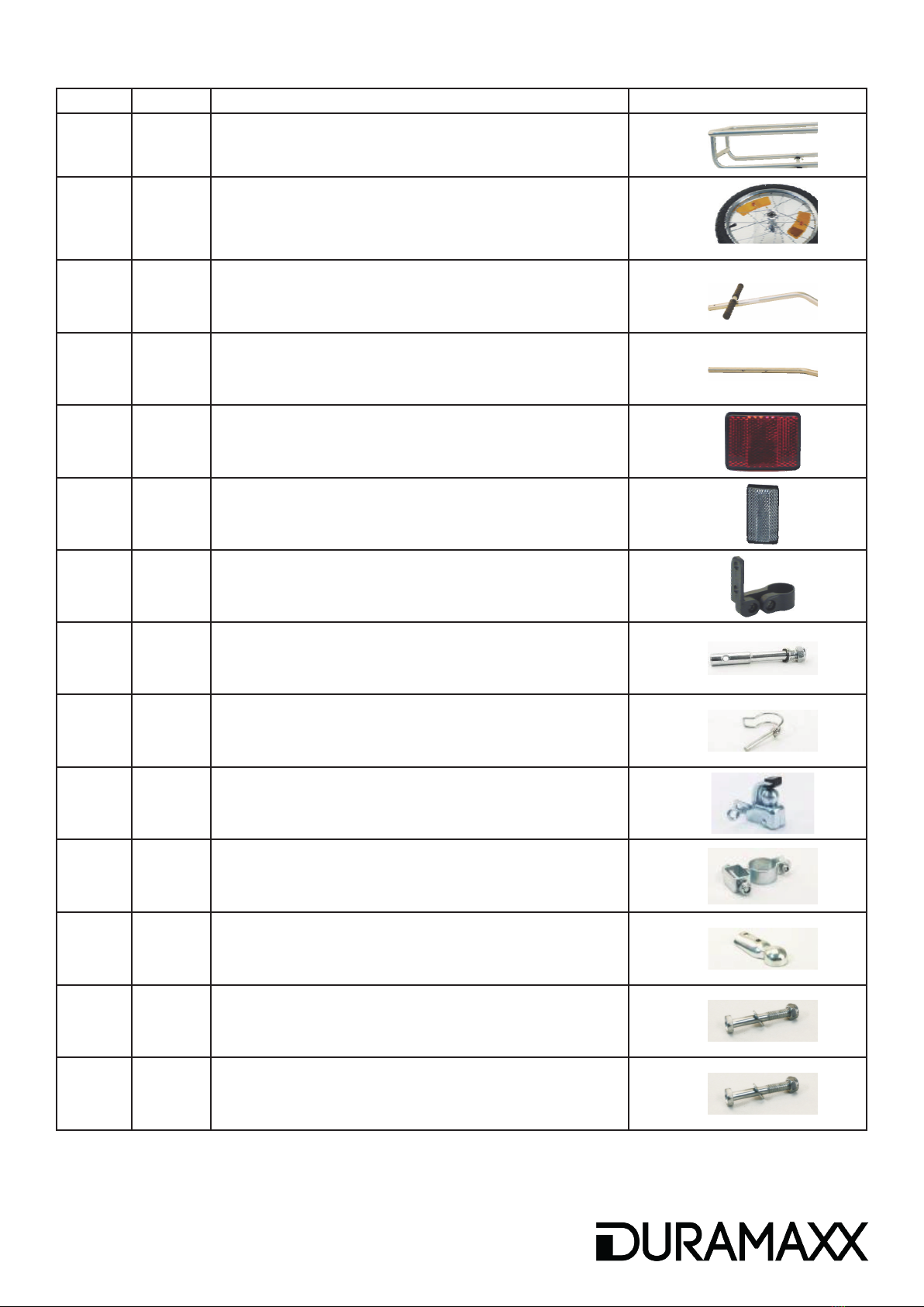
Parts List
# Pieces Description Picture
1 1x Transport box

8 9
# Pieces Description Picture
2 1x Base frame (including protective covers)
3 2x 16“ wheels with pneumatic tyres
4 1x Tow bar with handle section
5 1x Tow bar with intermediate section
6 2x Red reectors
7 2x White reectors
8 4x Reektor mounting
9 2x Axle
10 1x Pin with safety catch
11 1x Ball-type coupling
12 1x Saddle support mounting
13 1x Coupling
14 2x M8 screw (6cm) (incl. Washer and Nut)
15 1x M8 screw (3,5cm) (incl. Washer and Nut)

10
# Pieces Description Picture
16 2x M6 screw (3,5cm) (incl. Washer and Nut)
17 2x Plastic shims
18 1x M8 screw (5,5cm) (incl. Washer and Nut)
19 1x M6 screw (2,3cm) (incl. Washer and Nut)
Assembly
Step 1
Remove the two black transport protectors
from the frame (2)
Step 2
Fit the reector mounting (8) to the frame (2), as shown. Fit
the two red reectors (6) to face the rear, and the two white
reectors (7) to face the front.
After tting the reector mountings (8) to the frame (2), push
each reector (6+7) into its respective mounting (8).

10 11
Step 3
Remove the locknut and washer from the axle (9).
Insert the axle (9) through the hub of each 305 mm (16“) wheel
(3). Ret the washer to the axle (9), then tighten the locknut.
Ensure that each locknut is correctly tightened. Check the lock-
nuts at regular intervals for correct tightness.
Step 4
Join the tow bar to the handle element (4) and intermediate
section (5). Use the 5.5 cm M8 screw (15) for this purpose.
Now t the assembled tow bar (4+5) to the frame (2). Use the
two 6 cm-long M8 screws (14) for this purpose.

12
Step 5
Fit the ball coupling (13) to the handle section (4) of the
tow bar. Use the two 3.5 cm-long M6 screws (16) for this
purpose.
Step 6
Secure the saddle-support mounting (12), with the help of
the plastic shims (17), to the saddle pillar of your bicycle.
Now use the screw (18) that is ready-tted to the saddle
support mounting (12) to attach the ball-head coupling (11)
to the saddle support mounting (12).

12 13
Step 7
Push the axle (9) of
each wheel (3) into its
mounting on the frame
(2).
Secure using the 5 cm
pin with safety catch
(10).
Step 8
Pull forwards the safety catch on the ball-head element (11)
and attach the ball coupling (13).
Tighten the securing screw in order to hold the coupling in place.
This will prevent the ball-head coupling and tow bar becoming
separated during use.
You‘re good to go! Good job!
Manufacturer
CHAL-TEC Vertriebs- + Handels GmbH, Wallstraße 16, 10179 Berlin.
This manual suits for next models
1
Table of contents
Languages:
Other Duramaxx Bicycle Accessories manuals