manuals.online logo
Brands
  1. Home
  2. •
  3. Brands
  4. •
  5. Duro Dyne
  6. •
  7. Control System
  8. •
  9. Duro Dyne DynaTite CL6-WC2 User manual

Duro Dyne DynaTite CL6-WC2 User manual

Step 1: Insert and tighten the Dyna-
Stud into a threaded receptacle of the
corresponding size. A locking jam nut
is recommended to prevent the Dyna-
Stud from turning. *If using Drop-In
see instructions below.
®
End Fixings Installation Instructions
Swaged
Dyna-Stud
*When using Dyna-Stud Drop-In
(sold separately)
:
Before
starting
to drill the
hole, it is
important
that eye
and ear
protection
are used.
Step 1: Insert a carbide tip
masonry bit into the ham-
mer-drill chuck and tighten
it in place. The depth of
the hole to be drilled can
easily be set by using the
depth gauge on the drill
or by wrapping the bit with
tape at the required depth.
Make sure that the hole
depth will allow the anchor
to be flush with the surface
of the concrete.
Step 2: Make sure the
hammer drill is in the
hammer mode and start
drilling your hole. Continue
drilling until the tape on the
bit or the drill gauge meets
the base material - this
means that the required
depth has been reached.
Step 3: Before proceeding
with installation, the hole
must be cleaned of all
concrete dust to ensure
proper fastening. Use a
wire brush, a vacuum or
compressed air to clean
out the hole completely.
Step 4: Next, insert the
drop-in anchor with the
open side up. Drop the
anchor into the hole. Tap
lightly to get the anchor
flush with the base
material.
Step 5: Now, take the
setting tool and insert
it into the anchor.
Strike the setting tool
with a hammer until
the lip of the anchor
touches the lip of the
setting tool. This will
ensure the anchor is
properly set.
CAUTION
Step #1: Pass the end of the wire rope
around the anchor point and through
the cable loop.
Step 2: Using the appropriate cable lock
(see the chart on back), pull adjustment
pin back and pass the end of the wire rope
through the Dyna-Tite Cable Lock.
Looped Cable
Assembly Eyelets
Step 1: Attach the wire rope to
a convenient anchor point with
appropriate fastener.
Step 3: Loop the wire rope around the duc-
twork or through attachment bracket and
back up through the Cable Lock.
ALWAYS CONFIRM ENGAGEMENT OF CABLE LOCK ON WIRE BEFORE APPLYING LOAD
'L'
'L'
'L'
1-1/2"
(LISTED)
CABLE
(LISTED)
45°EYELET
(LISTED)
CABLE
90°EYELET
(LISTED)
(LISTED)
CABLE
BRACKETw/DRIVE PIN
'L'
'L'
'L'
1-1/2"
(LISTED)
CABLE
(LISTED)
45° EYELET
(LISTED)
CABLE
90° EYELET
(LISTED)
(LISTED)
CABLE
BRACKET w/DRIVE PIN
®
End Fixings Installation Instructions
IMPORTANT WARNINGS AND RECOMMENDATIONS
When installing Duro Dyne Dyna-Tite cable attachments to buildings or equipment careful consideration must
be made to the attachment method and the material being attached to. It is the responsibility of the installer for
the proper selection, installation and appropriateness of the attachment to the job specifications and any codes.
Duro Dyne can give general guidance, but any questions regarding this should ultimately be directed to the project
engineer of the job.
TO ENSURE THE INTEGRITY OF ANY DYNA-TITE CABLE LOCK SYSTEM OR ACCESSORY,
USE ONLY CABLE LOCKS AND WIRE ROPE SUPPLIED BY DURO DYNE.
81 Spence Street • Bay Shore, NY 11706 • Tel: 631-249-9000 • Fax: 631-249-8346
R
DO NOT EXCEED THE SAFE WORKING LOAD RANGE OF THE PRODUCT
THE PRODUCTS ARE PROVIDED ON AN “AS IS” BASIS; THERE SHALL BE NO EXPRESS OR IMPLIED
WARRANTY, INCLUDING WITHOUT LIMITATION, WARRANTY OF MERCHANTABILITY OR FITNESS
FOR A PARTICULAR PURPOSE. SUPPLIER SHALL NOT UNDER ANY CIRCUMSTANCES, BE LIABLE FOR
INDIRECT, SPECIAL OR CONSEQUENTIAL DAMAGES OR LOST PROFITS.
Wire Rope
Safe Working Load Range
at 5:1 Safety Factor
WC3-CL12 25-150 lbs.
(12-68 kg)
Wire Rope
Safe Working Load Range
at 5:1 Safety Factor
WC4-Cl18 25-250 lbs.
(12-114 kg)
Wire Rope
Safe Working Load Range
at 5:1 Safety Factor
WC2-CL6 10-75 lbs.
(5-34 kg)
WORKING LOAD RANGE
Duro Dyne Looped Cable Assembly, Eyelets, and Dyna-Studs are limited to the working load limit of the appropriate
Dyna-Tite Cable Lock used with it. See charts below.
12/27/18
®
CL12-WC3CL6-WC2
CL18-WC4
FOR STATIC LOAD APPLICATIONS ONLY!
ALWAYS CONFIRM ENGAGEMENT OF CABLE LOCK ON WIRE BEFORE APPLYING THE LOAD: By pushing the adjustment pin in the opposite direction of the
arrows on the cable lock and then pulling the cable also in the opposite direction of the arrows on the cable lock.
PULL ADJUSTMENT PIN BACK AND PASS WIRE ROPE THROUGH DYNA-TITE CABLE LOCK: Failure to pull adjustment pin rst may cause damage to serrated
teeth and reduce holding capacity.
TO ENSURE HANGING SYSTEM INTEGRITY AND SAFETY: Use only Duro Dyne wire rope.
DO NOT EXCEED THE WORKING LOAD LIMIT (WLL) OF THE CABLE LOCK: Each product is load rated and incorporates a minimum safety factor of 5:1. This WLL
takes into account the specication criteria of the Dyna-Tite Cable Lock and the wire rope.
DO NOT USE ON COATED WIRE ROPE: It is important to maintain the metal to metal contact between the locking pawls in the Dyna-Tite and the wire rope.
DO NOT APPLY PAINT OR OTHER COATING: to any part of the assembly as these may impair the free movement of the locking pawls inside the Dyna-Tite Cable
Lock.
DO NOT APPLY LUBRICANT: to any part of the assembly as this will alter the surface nature of the wire rope and attract dirt and debris.
DO NOT USE FOR LIFTING: (Under Hook slings) This product is designed for static load applications only.
KEEP THE PRODUCT CLEAN AND FREE FROM DIRT: Any dirt should be removed from the product prior to assembly.
INSPECT PERIODICALLY: Upon inspection, discard and replace if worn, distorted, or damaged.
REMOVE DAMAGED WIRE ENDS: Using a designated pair of wire rope cutters prior to inserting into the Dyna-Tite Cable Lock.
FOR DRY LOCATIONS ONLY
DO NOT USE IN CHLORINATED ATMOSPHERES SUCH AS POOLS AND NATATORIUM
GYMNASIUM INSTALLS MUST BE USING LOCKING CABLE LOCKS ONLY

This manual suits for next models

2

Other Duro Dyne Control System manuals

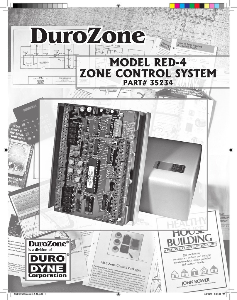
Duro Dyne DuroZone RED-4 User manual

Duro Dyne

Duro Dyne DuroZone RED-4 User manual

Duro Dyne DuroZone SMZ-AC User manual

Duro Dyne

Duro Dyne DuroZone SMZ-AC User manual

Popular Control System manuals by other brands

A1S Group Evo1-MCP 1 Technical manual

A1S Group

A1S Group Evo1-MCP 1 Technical manual

Nordyne Airzone iQ Zone user manual

Nordyne

Nordyne Airzone iQ Zone user manual

Varifan MVS-1C user guide

Varifan

Varifan MVS-1C user guide

BLAUBERG Ventilatoren S21 user manual

BLAUBERG Ventilatoren

BLAUBERG Ventilatoren S21 user manual

Pellini ScreenLine F Series manual

Pellini

Pellini ScreenLine F Series manual

Exhausto EXact Basic instructions

Exhausto

Exhausto EXact Basic instructions

Parker Sea Recovery Aquamatic Quick start & troubleshooting guide

Parker

Parker Sea Recovery Aquamatic Quick start & troubleshooting guide

Siemens SINUMERIK 840D Operator's guide

Siemens

Siemens SINUMERIK 840D Operator's guide

GE POWER LEADER DEH-210 user guide

GE

GE POWER LEADER DEH-210 user guide

KAR-TECH CAN RANGER Operation manual

KAR-TECH

KAR-TECH CAN RANGER Operation manual

RIB STOPPER manual

RIB

RIB STOPPER manual

Laguna Tools MCNC Plasma 48 x 48 manual

Laguna Tools

Laguna Tools MCNC Plasma 48 x 48 manual

Sony PWS-110CM1 Operation manual

Sony

Sony PWS-110CM1 Operation manual

Piusi MC BOX Instructions for installation, use and maintenance manual

Piusi

Piusi MC BOX Instructions for installation, use and maintenance manual

Crestron IRP2 installation guide

Crestron

Crestron IRP2 installation guide

Guardian EMC3B manual

Guardian

Guardian EMC3B manual

ROJ PCS 200 Original instructions

ROJ

ROJ PCS 200 Original instructions

WEISS HP140 operating instructions

WEISS

WEISS HP140 operating instructions

manuals.online logo
manuals.online logoBrands
  • About & Mission
  • Contact us
  • Privacy Policy
  • Terms and Conditions

Copyright 2025 Manuals.Online. All Rights Reserved.