Dust Free 19300 User manual

LIGHTSTICK®
Germicidal UV-C Ultraviolet Light
Lightstick #19300
Installation & Operation Manual
INCLUDED INSIDE BOX
• Power module
• Germicidal UV lamp
• Remote lamp extension cord
• Mounting bracket
• UV safety viewport
• UV radiation hazard labels
• UV duct label
• Installation & operation manual
• Installation hardware
GENERAL
This product emits germicidal ultraviolet
(UV-C) light to dose the cooling coil, drain
pan, and internal surfaces of HVAC
systems for improved indoor air quality
where the light shines.
BEFORE INSTALLING OR
MAINTAINING
• Read all instructions carefully. Failure
to do so could damage the equipment
or cause harm to yourself or others.
• Acknowledge all warnings.
• Only qualified technicians should
perform the installation.
• Install in accordance with national and
local wiring regulations and
mechanical codes.
• This appliance contains a UV-C lamp.
213097-00 Rev. 3A 02/24

DUST FREE®LIGHTSTICK®INSTALLATION & OPERATION MANUAL
2
Germicidal
UV-C Lamp
Power Module
UNIT OVERVIEW
Fig. 1 Unit component identication.
Direct Mounting 15.1 in (384 mm)
2.0 in
(50 mm)
3.5 in
(89 mm)
Bracket Mounting 19.1 in (485 mm)
Fig. 2 Minimum clearances.
INCLUDED MOUNTING HARDWARE
• (2) 8-32 brass knurled nuts
• (2) 6-20 x 7/16in Philip pan screws
• (3) 8-18 x 3/4in Philip pan screws
• (3) 8-18 x 2-1/2in Philip pan screws
• (1) Lamp knockout gasket
• (2) 1/8in ID rubber washers
4.75”3.16”
3.35”
5.3”
1.75”

3
DUST FREE®LIGHTSTICK®INSTALLATION & OPERATION MANUAL
SPECIFICATIONS
U.S. Patent Nos. 5,334,347, 5,817,276, 6,245,293, 6,267,924, 6,280,686, 6,313,470, 6,627,000, 6,539,727,
6,932,494, 6,550,257.
EPA Establishment No. 73316-TX-1
Dust Free® uses independent labs and universities for product testing.
Visit http://www.dustfree.com/testing.
The product and technologies described are not medical devices, and are not intended to diagnose,
treat, cure, or prevent any disease or illness.
UL COMPLIANCES:
UL 60335-2-40:2022 Ed.4 , UL 1598:2021 Ed.5, CSA C22.2#60335-1:2016 Ed.2, and
CSA C22.2#250.0:2021 Ed.5
Certain Conditions of Acceptability (COAs) required during install to meet all
compliances. See UV Installation Notes on page 4 for details.
This unit has been evaluated for use with non-integral UV-C germicidal lamp system
field installation accessory model #19302 and #19303.
Power: 24VAC (Expanded range ballast: 20V-30V), 50/60Hz, 1.0A.
3000V surge protection.
Cordage: 3-ft 24V power cord. 4-ft lamp cord.
UL 2998 validated no ozone.
Meets California ozone emissions limit: CARB certied.
High-humidity, water-resistant, 15" lamp length.
Power Module: 4.75″L x 3.16″W x 1.75″H
Mounting Bracket: 3.5″L x 2.25″W x 3.5″H
Weight: 2 lbs.
9,000 hour.
Lightstick #19300
Model
Electrical
Ozone
Lamp
Warranty
Replacement
Parts
Size and
Weight
Lamp Life
Injection-molded thermoplastic co-polymer high-strength
power module.
Construction
4-year on power module. 1-year on lamp.
UV-C Lamp: #19302 Replace lamp annually.

DUST FREE®LIGHTSTICK®INSTALLATION & OPERATION MANUAL
4
UV INSTALLATION NOTES
• Unintended use of the appliance or damage to the housing may result in the escape of
dangerous UV-C radiation. UV-C radiation may, even in small doses, cause harm to the
eyes and skin.
• Appliances that are obviously damaged must not be operated.
• The appliance must be disconnected from the supply before replacing the UV-C LAMP.
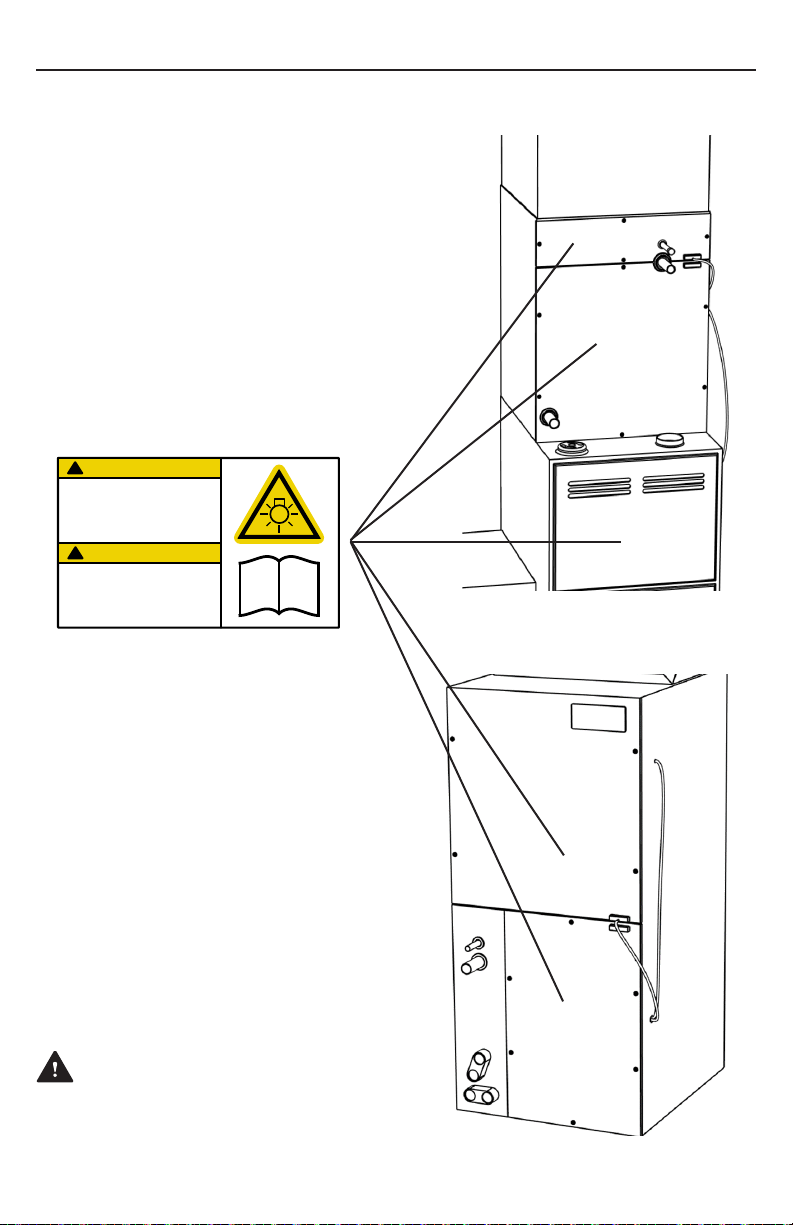
• Doors and access panels bearing the ultraviolet radiation hazard label, which may have
UV-C SPECTRAL IRRADIANCE greater than 1.7 µW/cm, are provided with an interlock
switch to interrupt the power to the UV-C LAMPS for your safety. Do not override. See
figure 3.
• To comply with UL Standards, a magnetic switch must be deployed across all access
panels and doors that can expose an operator to more than of 1.7 µW/cm UV intensity.
• To comply with UL Standards, a UV-C Radiation Hazard label must be placed on any
doors or access panels which can expose an operator to more than 1.7 µW/cm of UV
intensity.
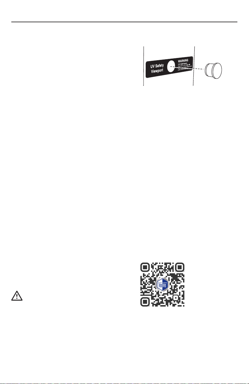
• Before opening doors and access panels bearing the ULTRAVIOLET RADIATION
hazard symbol for the conducting USER MAINTENANCE, it is recommended to
disconnect the power.
• UV-C BARRIERS bearing the ULTRAVIOLET RADIATION hazard symbol should not be
removed.
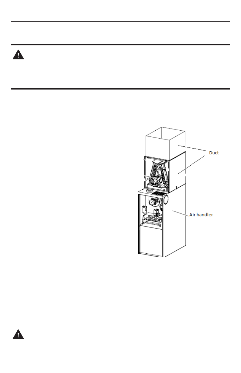
• Do not operate UV-C LAMPS outside of the appliance.
WIRING AND TRANSFORMER INSTALLATION NOTES
This device requires a constant 24V-AC power source. It is recommended that the device
be powered by a dedicated, non-cycling, 40VA transformer. Cycling this UV light will void the
lamp’s warranty and lessen the eective lifetime of the lamp. If powering from an existing
transformer already integrated on a furnace, air handler, or other appliance, an upgrade may
be required to the OE transformer. Ensure there is adequate volt-ampere (VA) capacity on
the existing transformer to support an additional 1.4A draw from this product
1. Verify the available volt amperes prior to connecting the UV xture to the 24VAC circuit. Energize
all 24VAC components so they reach their maximum amp load (Straight cool system - activate
cooling. Heat pump - activate heating mode.)
2. After obtaining the available volt amperes, determine if the existing transformer can accommodate
a 1.4 amp load.
3. Beware that inadequate transformers may initially seem to power up the circuit only to then
overheat as a result of an overdrawing system.
4. After installing the UV xture, energize all 24VAC components at their full amp draw, including the
UV xture, and ensure that all systems are operational and that fuses remain intact.
5. If the SUPPLY CORD is damaged, it must be replaced by the manufacturer, its service agent, or
similarly qualied persons in order to avoid a hazard.
i
UV
!
CAUTION
AVERTIR
!
UV radiation hazard.
Disconnect power before
opening this access panel.
Follow operating
instructions.
219320-00
Risque de rayonnement UV.
Débranches l'alimentation
avant d'ouvrir ce panneau.
Suivre les instructions
d'utilisation.
Fig. 3 Disconnect power before opening any doors
or access panels bearing this label. See page 9.

5
DUST FREE®LIGHTSTICK®INSTALLATION & OPERATION MANUAL
UV INSTALLATION LOCATION
This device may be installed in an air
handler unit, a cased evaporator coil, or in
an air plenum/duct.
If the UV device is installed on the inlet
side (return air side) of a coil, make sure
that the UV rays are directed away from
any lter medias, plastic duct lining, plastic
components, or accessible doors and
panels.
If the UV device is installed near an air lter,
check with lter manufacturer for UV-C
resistance properties.
If the desired UV installation location is
intended to irradiate an air lter, to neutralize
the microbiological matter on the air lter
surface, such as would be found in the
return air drop of a basement application or
in the return plenum of a horizontal system
in an attic; take precautions as described in
note above, and make sure the UV xture is
placed on the return side of the lter.
DO NOT INSTALL THE UV FIXTURE ON
EITHER SIDE OF THE FILTER IN HALL /
CLOSET RETURN AIR APPLICATIONS.
The power module must be mounted directly to
a metal surface.
This will help the ballast dissipate heat. Failing to mount the ballast properly
will void warranty and may lead to pre-mature UV lamp failure.
Fig. 3 Cased evaporator coil/furnace
installation.
WARNING
UV Light Hazard.
Can cause serious eye and skin damage.
Do not look at UV-C light. Wear UV-C eye and
skin protection.

DUST FREE®LIGHTSTICK®INSTALLATION & OPERATION MANUAL
6
• With the lamp cordage facing away from
the mounting surface, install the power
module in a suitable location on the side
of the system or within the control panel
of the air handler using the two long
self-drilling screws (included). Do not
overtighten.
• Drill a 7/8” knockout in the outer sheet
metal where the remote lamp extension
cord will be inserted.
• Connect the power module to constant
24VAC power.
• Connect lamp to power module.
Connectors are keyed for proper
alignment.
POWER MODULE INSTALLATION (Remote Lamp)
Fig. 5 Secure power module to air
handler or duct with long screws. Do not
overtighten.
NOTICE
Fully Seat Lamp Connector.
Failure to properly seat lamp connector could
result in improper lamp operation and/or
compromise water resistance.
REMOTE LAMP INSTALLATION (A-Coil Delta Plate)
• Drill a 7/8” knockout into the delta plate
and place gasket (included) around
knockout.
• Insert lamp directly into knockout and
secure the lamp to the delta plate with
two self-drilling screws. (Screws and
rubber washers included.)
• Connect remote lamp extension cord.
Note: A-Coil delta plate installation
does not use lamp bracket.
Fig. 4. Insert lamp into delta plate
knockout and secure with screws
and washers. Connect remote lamp
extension cord.
WARNING
UV Light Hazard.
Can cause serious eye and skin damage.
Do not look at UV-C light. Wear UV-C eye and
skin protection.
NOTICE
Clean lamp prior to installation.
Use a cotton cloth to remove dirt and
fingerprints. Failure to do so could shorten the
lamp’s lifespan.
NOTICE
Lamp cleaning not required after
installation.
Reference specifications page for lamp
replacement part number and schedule.

7
DUST FREE®LIGHTSTICK®INSTALLATION & OPERATION MANUAL
WARNING
Electric Shock Hazard.
Can cause injury or death.
Disconnect all electrical power supplies
before servicing.
WARNING
For Use With 24VAC Only.
Do not exceed voltage rating.
Severe damage to device and/or fire could
result. Verify proper voltage.
• Drill a 7/8” knockout in the outer sheet
metal where the power cord will be
inserted.
• Connect the power module to constant
24VAC power.
• Connect lamp connector to power
module connector. Connectors are
keyed for proper alignment.
POWER MODULE
INSTALLATION (Direct Lamp)
DIRECT LAMP INSTALLATION (A-Coil Delta Plate)
• Drill a 7/8” knockout in the outer sheet
metal where the lamp will be centered on
the return side of the coil. See diagram.
• Place gasket (included) around knockout.
• Insert lamp into power module and
secure with self-drilling screws.
(Included.)
• Insert lamp/power module assembly
directly into knockout and secure with
self-drilling screws (Included.) Note:
A-Coil delta plate installation does not
use lamp bracket. Fig. 6 Insert lamp into power module
and secure with screws.
Fig. 7 Insert assembly into delta plate
knockout and secure with screws.

DUST FREE®LIGHTSTICK®INSTALLATION & OPERATION MANUAL
8
REMOTE LAMP INSTALLATION (W-Coil / A-Coil Bracket Mount)
• Disconnect power to the air handler and
open access panels.
• Slit insulation on the back or side wall
of air handler and attach bracket using
screws.
• Secure the lamp to the lamp bracket with
the provided knurled nuts.
• Install power module in accordance with
steps dened on page 6.
Fig. 8 Attach lamp to lamp bracket and
install in desired location.

9
DUST FREE®LIGHTSTICK®INSTALLATION & OPERATION MANUAL
UV-C HAZARD LABEL PLACEMENT
• To comply with UL Standards, a UV-C
Radiation Hazard label must be placed
on any doors or access panels which can
expose an operator to more than 1.7 µW/
cm of UV intensity.
• Place UV-C Radiation Hazard labels at
recommended locations.
Fig. 9 Coil Install.
Fig. 10 Air handler install.
WARNING
UV Light Hazard.
Can cause serious eye and skin damage.
Do not look at UV-C light. Wear UV-C eye and
skin protection.
i
UV
!
CAUTION
AVERTIR
!
UV radiation hazard.
Disconnect power before
opening this access panel.
Follow operating
instructions.
219320-00
Risque de rayonnement UV.
Débranches l'alimentation
avant d'ouvrir ce panneau.
Suivre les instructions
d'utilisation.

DUST FREE®LIGHTSTICK®INSTALLATION & OPERATION MANUAL
10
• Each time the lamp is replaced, note
the date of lamp install and the next
recommended date of replacement on the
duct label.
• Lamp does not require any routine
maintenance, such as cleaning.
• Reference specications page for lamp
replacement schedule and replacement
part numbers.
Register all new Dust Free equipment online
at https://dustfree.com/resources/warranty/
• Adhere the provided UV duct label to the
outside of the duct near the installation
location and drill a 5/8” knockout as
indicated on the label. Press the UV safety
viewport into knockout.
• Close all access panels and reconnect
power to the air handler.
• Verify that a blue glow can be seen
through the UV safety viewport.
LAMP MAINTENANCE
WARRANTY REGISTRATION
INSTALL UV SAFETY VIEWPORT
NOTICE
Replace Lamp Per Recommended
Maintenance Schedule.
UV-C lamps expend their germicidal
effectiveness over time. Replace the lamp even
if it appears to be operating normally.
Fig. 15 Press viewport into place.

11
DUST FREE®LIGHTSTICK®INSTALLATION & OPERATION MANUAL
UVC lamp not
operating
Use a multimeter
to test for correct
voltage at ballast
input wire
21-32V present? No
Correct the
voltage source
issue
Turn off power.
Next, check that the
UVC bulb is fully
seated onto the
connector
Return UV system and
turn power back on
UVC Lamp now
powering up? Replace Lamp
No
DONE
Yes
Replace Power
Module
UVC lamp now
powering up? No
Yes
Safety magnetic
switch used to
interlock the UVC
device?
Ensure safety switch
leads coming off ballast
are combined/closed
No
Yes
Temporarily bypass the
magnetic switch by
connecting both safety
switch signal wires
together
Yes
UVC lamp now
powering up?
Refer to installation
manual to properly
position magnetic switch
Yes
No
TROUBLESHOOTING GUIDE
DANGER
Ultraviolet (UVC) Radiation Hazard.
Any exposure will cause significant eye
damage and may cause skin damage.
DO NOT look into UVC light source.
Access panels must be in place during
appliance operation.

DUST FREE®LIGHTSTICK®INSTALLATION & OPERATION MANUAL
12
Dust Free LP. warrants this Lightstick to be free from defects in materials and workmanship under
normal use and service, for a period of four (4) years from the date of purchase. This warranty does
not cover UV-C lamp(s), which carry a one (1) year warranty from the date of installation. Products
must be registered upon install at https://dustfree.com/resources/warranty.
This warranty does not cover cosmetic damage, damage due to acts of God, damage as a result of
handling or shipment, negligence, misuse, connection to improper voltage, improper maintenance,
or abuse. This warranty is void if defect(s) result from failure to have this unit installed by a qualied,
properly licensed, heating and air conditioning contractor in compliance with all local building and
construction codes.
Dust Free LP’s exclusive obligation under this warranty shall be to supply, without charge, a
replacement for any covered component of the Lightstick which is found to be defective within the
parameters dened herein. Dust Free LP reserves the right to replace or repair the defective part or
component.
DUST FREE LP SHALL NOT BE LIABLE FOR ANY LOSS OR DAMAGE OF ANY KIND, INCLUDING
ANY INCIDENTAL OR CONSEQUENTIAL DAMAGES RESULTING, DIRECTLY OR INDIRECTLY, FROM
ANY BREACH OF WARRANTY, EXPRESS OR IMPLIED, OR ANY OTHER FAILURE OF THIS PRODUCT.
(Some states do not allow the exclusion or limitation of incidental or consequential damages, so
this limitation may not apply to you.) THE WARRANTIES SET FORTH HEREIN ARE EXCLUSIVE
AND DUST FREE LP EXPRESSLY DISCLAIMS ALL OTHER WARRANTIES, WHETHER WRITTEN
OR ORAL, IMPLIED OR STATUTORY, INCLUDING BUT NOT LIMITED TO ANY WARRANTIES OF
MERCHANTABILITY, WORKMANSHIP, OR FITNESS FOR A PARTICULAR USE. If the limited warranty
is void due to failure to use a qualied contractor all disclaimers of implied warranties shall be
eective upon installation.
How to make a warranty claim or have questions answered:
Should you have a warranty claim or questions about the warranty policy, contact the distributor
or dealer from which you purchased the product. Proof of original purchase, prior product online
registration, and proof of identity that the original purchasing party is ling the claim is required in
order to initiate a warranty claim. Defective parts must be returned no later than thirty (30) days after
the failure to the installing contractor together with the model number, serial number, and date of
installation. All service and removal must be performed by a licensed HVAC contractor. You must pay
shipping charges and all other costs of warranty service. Warranty is only valid the United States and
Canada.
THIS WARRANTY SHALL NOT OBLIGATE THE MANUFACTURER FOR ANY LABOR COSTS AND
SHALL NOT APPLY TO DEFECTS IN WORKMANSHIP OR MATERIALS FURNISHED BY THE
INSTALLING CONTRACTOR AS CONTRASTED TO DEFECTS IN THE GERMICIDAL LIGHT ITSELF.
NOTE: Do not return any products or parts to the factory without a factory issued Return
Authorization number issued by the Dust Free LP customer service department.
In the event you have any questions concerning the use and care of this product or this warranty
which have not been answered to your satisfaction by the distributor or dealer, please call or write
the factory.
Dust Free®
PO Box 519, 1112 Industrial Park Drive
Royse City, TX 75189
1-972-635-9564
www.dustfree.com
WARRANTY
Table of contents
Other Dust Free Lighting Equipment manuals