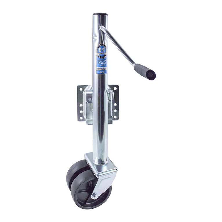
Dutton-Lainson 6400 Series User manual

Ref. Description Part No.
A 6812B Miter Gear Kit 5224373
B 6804 Clamp & Bolt Kit 5224431
C 6” Wheel Kit (6806) 5224407
D 6” Wheel Bracket Ass’y 5226360
D 8” Wheel Bracket Ass’y 5226386
F 8 Inch Wheel (6807) 5224100
G Cover Bracket Kit 5222351
H 6808 Swivel Plate Kit 5224258
(4 Bolt) for 1/2” Handle
H 6808 Swivel Plate Kit 5224449
(4 Bolt) for 3/8” Handle
J 6809 Swivel Plate Kit 5224266
(2 Bolt) for 1/2” Handle
J 6809 Swivel Plate Kit 5224829
(2 Bolt) for 3/8” Handle
P Removable Foot & Clevis Pin (6606) 5225412
Q Removable Caster Wheel (6604) 5224142
R Carriage Bolt 3/8”-16 x 1” (2) 205389
T Clover Leaf Washer 403283
U Swivel Bracket Washer (4 Bolt) 403282
W Flanged Lock Nut 3/8” - 16 (2) 205285
X Jack Handle Assy w/pin (6810A) 5224464
Y Swivel Handle 3/8” Dia. Kit 5224498
Y Swivel Handle 1/2” Dia. Kit 5224548
6400 Series Tongue Jack Parts List
Ref. Description Part No.
CC Weld-On Swivel Bracket, 3/8” Handle (6611) 403411
CC Weld-On Swivel Bracket, 1/2” Handle (6616) 5226717
DD Retaining Ring 5226725
FF Hardened Flat Washer (2) 207357
GG Plastic Thrust Washer 207356
HH Hex Bolt 3/8”-16 X 1” (3) 205043
JJ Lock Washer 3/8”-16 (3) 205042
KK Hex Nut 3/8”-16 (3) 205050
LL Weld-On Swivel Bracket (6610) 5226675
MM End Cap 5223540
NN Weld on Strap 403563
RR 6684 4-1/2” Channel Mount Plate 5221924
RR 6685 5-1/2” Channel Mount Plate 5221932
RR 6686 6-1/2” Channel Mount Plate 5221940
Bolted Swivel Mount Assemble jack as shown in the
parts drawing making sure that the protrusion in the center
of the clover washer enters the center hole in the swivel
plate. Printing on the swivel bracket washer should not be
visible after assembly. Tighten nuts evenly.
Snap Ring Swivel Mount Assemble jack as shown in
the parts drawing and install retaining ring with snap ring
pliers. Make certain that snap ring is securely seated in
groove.
6400 SERIES TONGUE JACK
ASSEMBLY
Minimal maintenance is required to keep your tongue jack
looking new and in good working order. Protect the finish
by keeping it clean and waxed. Lubrication is needed
if the jack cranks roughly or produces a grinding noise
when operated. With weight off the jack remove jack from
tongue. Remove end cap (MM). (See parts list on back
page.) Remove pin (1) holding handle in place. Remove
handle and miter gear (2). Turn jack upside down and
shake gently to allow miter gear (3) to drop out. Align
dowel pin (4) with hole in side of outer post assembly.
Gently tap outer post assembly sideways allowing dowel
pin to slip free from jackscrew and drop through hole in
outer tube. Tap top of jackscrew to remove inner tube
assembly. Do not attempt to remove screw from inner
tube. Lubricate screw, thrust bearing (FF), and miter
gears (2) and (3) with grease.
MAINTENANCE
Bolt-on Place jack on trailer tongue in a location that
avoids interference with the boat, trailer and tow vehicle
during all conditions of use. Make sure the jack cannot
contact the tow vehicle when making tight turns. Tighten
all bolts evenly.
Weld-on Weld on jack brackets need to be installed by
a competent welder. Determine location per instruction
above.
After bracket is painted, assemble jack according to the
parts drawing and assembly instructions above. Note that
bolts (QQ) are self-threading and require considerable
installation force.
A-Frame Insert jack through hole in coupler and secure
with bolts, lock washers, and nuts. A removable wheel or
foot can be purchased separately. CAUTION When
using the removable wheel with tongue weights over
250lb/114Kg, a No. 6612 support plate should be
securely welded to the bottom of the trailer frame.
Failure to do so could result in jack and coupler
damage.
MOUNTING
When jack reaches either end of its travel do not force
handle or damage to the jack will result. When moving
trailer by hand, crank jack to lowest position. Do not use
the jack as a convenient hand hold. Avoid rolling jack over
rough or soft surfaces. Raise jack completely before tow-
ing.
WARNING Use of a swivel type jack without the
swivel handle completely engaged could result in
the trailer tongue suddenly dropping and could
cause personal injury.
CAUTION Loads in excess of rating shown on
jack label will cause accelerated wear and possi-
ble failure. This jack is not for highway use. Never
tow trailer with load applied to jack.
OPERATION
DWG. NO. 203452T 3/20 ©2020 CORNHUSKER PRESS
A Dependable Company Since 1886
DUTTON-LAINSON COMPANY
Hastings, NE 68902 U.S.A. • Tel 402-462-4141 • Fax 402-460-4612
www.dutton-lainson.com • E-mail: [email protected]
MADE IN
U.S.A.
R
WARNING READ INSTRUCTIONS CAREFULLY BEFORE INSTALLING, OPERATING, OR
SERVICING THIS JACK. FAILURE TO COMPLY WITH INSTRUCTIONS COULD RESULT IN SERIOUS
INJURY. RETAIN THESE INSTRUCTIONS FOR FUTURE REFERENCE.
To order these accessories or
replacement parts contact your
D-L dealer or
Pour commander ces accessoires ou
des pièces de rechange, se mettre en
contact avec le concessionnaire D-L ou
Para pedir estos accesorios o
repuestos, comuníquese con el
concesionario de D-L o con
Dutton-Lainson Company
www.dlco.com
Tel: 800-569-6577
Fax: 402-460-4612
In Europe Contact:
IMDS
12-13 Eddystone Road
South Hampshire Business Park
Calmore S040 3SA, United Kingdom
EC Declaration of Conformity – Dutton-Lainson
Company, Hastings, NE 68902-0729 U.S.A.
manufactures and declares that the jack identi-
fied above fulfills all relevant provisions of the Directive
2006/42/EC. The technical file may be obtained from the
persons listed below.
Hastings, NE USA
March 5, 2020
Director of Engineering
Dutton-Lainson Company
Jack Singleton
IMDS
12-13 Eddystone Road
South Hampshire Business Park
Calmore S040 3SA, United Kingdom

Ref. Description Part No.
A 6812B Miter Gear Kit 5224373
B 6804 Clamp & Bolt Kit 5224431
C 6” Wheel Kit (6806) 5224407
D 6” Wheel Bracket Ass’y 5226360
D 8” Wheel Bracket Ass’y 5226386
F 8 Inch Wheel (6807) 5224100
G Cover Bracket Kit 5222351
H 6808 Swivel Plate Kit 5224258
(4 Bolt) for 1/2” Handle
H 6808 Swivel Plate Kit 5224449
(4 Bolt) for 3/8” Handle
J 6809 Swivel Plate Kit 5224266
(2 Bolt) for 1/2” Handle
J 6809 Swivel Plate Kit 5224829
(2 Bolt) for 3/8” Handle
P Removable Foot & Clevis Pin (6606) 5225412
Q Removable Caster Wheel (6604) 5224142
R Carriage Bolt 3/8”-16 x 1” (2) 205389
T Clover Leaf Washer 403283
U Swivel Bracket Washer (4 Bolt) 403282
W Flanged Lock Nut 3/8” - 16 (2) 205285
X Jack Handle Assy w/pin (6810A) 5224464
Y Swivel Handle 3/8” Dia. Kit 5224498
Y Swivel Handle 1/2” Dia. Kit 5224548
6400 Series Tongue Jack Parts List
Ref. Description Part No.
CC Weld-On Swivel Bracket, 3/8” Handle (6611) 403411
CC Weld-On Swivel Bracket, 1/2” Handle (6616) 5226717
DD Retaining Ring 5226725
FF Hardened Flat Washer (2) 207357
GG Plastic Thrust Washer 207356
HH Hex Bolt 3/8”-16 X 1” (3) 205043
JJ Lock Washer 3/8”-16 (3) 205042
KK Hex Nut 3/8”-16 (3) 205050
LL Weld-On Swivel Bracket (6610) 5226675
MM End Cap 5223540
NN Weld on Strap 403563
RR 6684 4-1/2” Channel Mount Plate 5221924
RR 6685 5-1/2” Channel Mount Plate 5221932
RR 6686 6-1/2” Channel Mount Plate 5221940
Bolted Swivel Mount Assemble jack as shown in the
parts drawing making sure that the protrusion in the center
of the clover washer enters the center hole in the swivel
plate. Printing on the swivel bracket washer should not be
visible after assembly. Tighten nuts evenly.
Snap Ring Swivel Mount Assemble jack as shown in
the parts drawing and install retaining ring with snap ring
pliers. Make certain that snap ring is securely seated in
groove.
6400 SERIES TONGUE JACK
ASSEMBLY
Minimal maintenance is required to keep your tongue jack
looking new and in good working order. Protect the finish
by keeping it clean and waxed. Lubrication is needed
if the jack cranks roughly or produces a grinding noise
when operated. With weight off the jack remove jack from
tongue. Remove end cap (MM). (See parts list on back
page.) Remove pin (1) holding handle in place. Remove
handle and miter gear (2). Turn jack upside down and
shake gently to allow miter gear (3) to drop out. Align
dowel pin (4) with hole in side of outer post assembly.
Gently tap outer post assembly sideways allowing dowel
pin to slip free from jackscrew and drop through hole in
outer tube. Tap top of jackscrew to remove inner tube
assembly. Do not attempt to remove screw from inner
tube. Lubricate screw, thrust bearing (FF), and miter
gears (2) and (3) with grease.
MAINTENANCE
Bolt-on Place jack on trailer tongue in a location that
avoids interference with the boat, trailer and tow vehicle
during all conditions of use. Make sure the jack cannot
contact the tow vehicle when making tight turns. Tighten
all bolts evenly.
Weld-on Weld on jack brackets need to be installed by
a competent welder. Determine location per instruction
above.
After bracket is painted, assemble jack according to the
parts drawing and assembly instructions above. Note that
bolts (QQ) are self-threading and require considerable
installation force.
A-Frame Insert jack through hole in coupler and secure
with bolts, lock washers, and nuts. A removable wheel or
foot can be purchased separately. CAUTION When
using the removable wheel with tongue weights over
250lb/114Kg, a No. 6612 support plate should be
securely welded to the bottom of the trailer frame.
Failure to do so could result in jack and coupler
damage.
MOUNTING
When jack reaches either end of its travel do not force
handle or damage to the jack will result. When moving
trailer by hand, crank jack to lowest position. Do not use
the jack as a convenient hand hold. Avoid rolling jack over
rough or soft surfaces. Raise jack completely before tow-
ing.
WARNING Use of a swivel type jack without the
swivel handle completely engaged could result in
the trailer tongue suddenly dropping and could
cause personal injury.
CAUTION Loads in excess of rating shown on
jack label will cause accelerated wear and possi-
ble failure. This jack is not for highway use. Never
tow trailer with load applied to jack.
OPERATION
DWG. NO. 203452T 3/20 ©2020 CORNHUSKER PRESS
A Dependable Company Since 1886
DUTTON-LAINSON COMPANY
Hastings, NE 68902 U.S.A. • Tel 402-462-4141 • Fax 402-460-4612
MADE IN
U.S.A.
R
WARNING READ INSTRUCTIONS CAREFULLY BEFORE INSTALLING, OPERATING, OR
SERVICING THIS JACK. FAILURE TO COMPLY WITH INSTRUCTIONS COULD RESULT IN SERIOUS
INJURY. RETAIN THESE INSTRUCTIONS FOR FUTURE REFERENCE.
To order these accessories or
replacement parts contact your
D-L dealer or
Pour commander ces accessoires ou
des pièces de rechange, se mettre en
contact avec le concessionnaire D-L ou
Para pedir estos accesorios o
repuestos, comuníquese con el
concesionario de D-L o con
Dutton-Lainson Company
www.dlco.com
Tel: 800-569-6577
Fax: 402-460-4612
In Europe Contact:
IMDS
12-13 Eddystone Road
South Hampshire Business Park
Calmore S040 3SA, United Kingdom
EC Declaration of Conformity – Dutton-Lainson
Company, Hastings, NE 68902-0729 U.S.A.
manufactures and declares that the jack identi-
fied above fulfills all relevant provisions of the Directive
2006/42/EC. The technical file may be obtained from the
persons listed below.
Hastings, NE USA
March 5, 2020
Director of Engineering
Dutton-Lainson Company
Jack Singleton
IMDS
12-13 Eddystone Road
South Hampshire Business Park
Calmore S040 3SA, United Kingdom
Other Dutton-Lainson Jack manuals
Popular Jack manuals by other brands

Daytona
Daytona DS300LRBL Owner's manual & safety instructions

Performance Tool
Performance Tool W1633 owner's manual

Sunex Tools
Sunex Tools 6622A owner's manual

HEIN-WERNER AUTOMOTIVE
HEIN-WERNER AUTOMOTIVE HW93659 Operating instructions & parts manual

Lippert
Lippert 285318 Installation and owner's manual

Sealey
Sealey 2010HL instructions