DVA AL Series User manual

Manuale d’istruzioni
Instruction Manual
Notice d’Utilisation
Handbuch
Manual de Istrucciones
serie
AL D.M. 174/2004
AL 5
AL 8
AL 12

IT INDICE
1. INTRODUZIONE
2. CONOSCERE L’APPARECCHIO
3. DESCRIZIONE DELL’APPARECCHIO
3.1 LA CONFEZIONE CONTIENE
4. CARATTERISTICHE TECNICHE
5. CARATTERISTICHE DELL’ACQUA D’ALIMENTO
6. PRECAUZIONI PER LA SICUREZZA
7. AVVERTENZE PER L’INSTALLATORE
8. RACCORDI RAPIDI
9. INSTALLAZIONE
9.1 COLLEGAMENTO ALLA RETE ELETTRICA
9.2 CONNESSIONE ALLA RETE IDRICA
9.3 CONNESSIONE ALLA RETE DI SCARICO
9.4 CONNESSIONE ALLA SALAMOIA
9.5 CONNESSIONE ALLO SCARICO DI TROPPO PIENO
10. MESSA IN FUNZIONE
10.1 SCELTA DELLA LINGUA
10.2 SCELTA DELL’ORA E DEL GIORNO CORRENTI
10.3 PROGRAMMA INSTALLAZIONE
11. PROGRAMMAZIONE DEL TIMER
11.1 AVVIO
11.2 PROGRAMMAZIONE DEI GIORNI DI RIGENERAZIONE
11.2.1 PROGRAMMAZIONE RIGENERAZIONI CON
PROGRAMMA SETTIMANALE
11.2.2 PROGRAMMAZIONE DELLA RIGENERAZIONE CON
INTERVALLO DEI GIORNI
11.3 IMPOSTAZIONE DELL’ORA DI RIGENERAZIONE
11.4 SCELTA DELL’ADDOLCITORE
11.5 PERSONALIZZAZIONE DEI TEMPI PER LA
RIGENERAZIONE
11.6 DISINFEZIONE RESINE E ALLARME SALE
(MONITORAGGIO DELLA PRESENZA DI SALE)
11.7 LETTURA DELLE IMPOSTAZIONI SUL DISPLAY
12.
MANCANZA DELLA CORRENTE E FERMI PROLUNGATI
13. COMANDI MANUALI
13.1 RIGENERAZIONE MANUALE
13.2 RITORNO IN POSIZIONE DI SERVIZIO
13.3 PROGRAMMA RISCACQUO RESINE
14.
REGOLAZIONE DUREZZA DELL’ACQUA TRAMITE
IL MISCELATORE
15.
MANUTENZIONE PER L’UTENTE
16.
MANUTENZIONE PER L’INSTALLATORE
17.
CONSIGLI UTILI
18. SMALTIMENTO
19. ALLARMI SEGNALATI SUL DISPLAY
20. PROBLEMA, CAUSA E RISOLUZIONE
UK INDEX
1. INTRODUCTION
2. HOW DOES A WATER SOFTENER WORK?
3. SYSTEM DESCRIPTION
3.1 THE PACKAGING CONTAINS
4. TECHNICAL DATA
5. FEED WATER FEATURES
6. SECURITY WARNINGS
7. INSTALLATION WARNINGS
8. QUICK JOINTS
9. INSTALLATION
9.1 ELECTRIC NETWORK CONNECTION
9.2 WATER NETWORK CONNECTION
9.3 UNLOADING SYSTEM CONNECTION
9.4 BRINE TANK CONNECTION
10. SETTING AT WORK
10.1 LANGUAGE SELECTION
10.2 CURRENT DAY AND TIME SELECTION
10.3 “SETTING AT WORK” PROGRAM
11. SETTING THE TIMER
11.1 START
11.2 SETTING THE REGENERATION DAYS
11.2.1
SETTING THE REGENERATIONS ON A WEEKLY PROGRAM
11.2.2
SETTING THE REGENERATIONS ON AN INTERVAL OF DAYS
11.3 SETTING THE REGENERATION TIME
11.4 SCELSELECTIONG THE WATER SOFTENER
11.5 CUSTOM REGENERATION DURATIONS
11.6 RESIN DISINFECTION AND SALT ALARM
(MONITORING SALT PRESENCE)
11.7 READING THE SETTINGS ON THE DISPLAY
12. BLACKOUT AND LONG DOWNTIME
13. MANUAL SETTINGS
13.1 MANUAL REGENERATIONS
13.2 RETURN TO THE OPERATIVE POSITION
13.3 RESINS RINSE PROGRAM
14. SETTING WATER HARDNESS USING THE MIXER
15. MAINTENANCE FOR THE USER
16. MAINTENANCE FOR THE INSTALLER
17. USEFUL ADVICE
18. DISPOSAL
19. ALARMS ON THE DISPLAY
20. PROBLEM, CAUSE AND SOLUTION
F INDEX
1. INTRODUCTION
2. CONNAÎTRE L’APPAREIL
3. DESCRIPTION DE L’APPAREIL
4. CARACTÉRISTIQUES TECHNIQUES
5. CARACTÉRISTIQUES DE L’EAU D’ALIMENTATION
6. CONSIGNES DE SÉCURITÉ
7. INSTRUCTIONS POUR L’INSTALLATEUR
8. RACCORDEMENTS RAPIDES
9. INSTALLATION
9.1 BRANCHEMENT ÉLECTRIQUE
9.2 RACCORDEMENT EN EAU
9.3 RACCORDEMENT AU RÉSEAU D’ÉGOUT
9.4 RACCORDEMENT À LA SAUMURE
9.5 RACCORDEMENT AU TUYAU DE TROP-PLEIN
10. MISE EN MARCHE
10.1 CHOIX DE LA LANGUE
10.2 CHOIX DE L’HEURE ET DU JOUR ACTUELS
10.3 PROGRAMME «MISE EN MARCH»
11. FONCTIONNEMENT
11.1 DÉMARRAGE
11.2 PROGRAMMATION DES JOURS DE RÉGÉNÉRATION
11.2.1 PROGRAMMATION DES RÉGÉNÉRATIONS SELON UN
PROGRAMME HEBDOMADAIRE
11.2.2 PROGRAMMATION DES RÉGÉNÉRATIONS SELON UN
INTERVAL DE JOURS
11.3 RÉGLAGE DE L’HEURE DE RÉGÉNÉRATION
11.4 CHOIX DE L’ADOUCISSEUR
11.5
PERSONNALISATION DES DURÉES POUR LA RÉGÉNÉRATION
11.6 DÉSINFECTION RÉSINES ET DÉTECTION DE SEL
(CONTRÔLE PRÉSENCE SEL)
11.7 LIRE LES RÉGLAGES SUR L’ÉCRAN
12. COUPURE DE COURANT ET ARRÊTS PROLONGÉS
13. COMMANDES MANUELLES
13.1 RÉGÉNÉRATION MANUELLE
13.2 RETOUR EN POSITION DE SERVICE
13.3 PROGRAMME RINÇAGE RÉSINES
14. RÉGLAGE DE LA DURETÉ DE L’EAU AVEC LE
MÉLANGEUR
15. ENTRETIEN POUR L’UTILISATEUR
16. ENTRETIEN POUR L’INSTALLATEUR
17. CONSEILS UTILS
18. ÉLIMINATION
2ATTENZIONE: il presente libretto costituisce parte integrante del prodotto e dovrà essere consegnato all’installatore,
il quale a sua volta lo riconsegnerà all’utente dopo avere compilato la tabella del controllo e data ultimo controllo

19. ALARMES VISUALISÉES SUR L’ÈCRAN
20. PROBLÈME, CAUSE ET SOLUTION
D INHALTSVERZEICHNIS
1. EINLEITUNG
2. DAS GERÄT KENNENLERNEN
3. BESCHREIBUNG DES GERÄTES
4. TECHNISCHE MERKMALE
5. MERKMALE DES SPEISEWASSERS
6. SICHERHEITSVORKEHRUNGEN
7. HINWEISE FÜR DEN INSTALLATEUR
8. SCHNELLANSCHLÜSSE
9. EINSTELLUNG
9.1 STROMANSCHLUSS
9.2 WASSERANSCHLUSS
9.3 ANSCHLUSS AN DAS ABFLUSSNETZ
10. INDIENSTNAHME
10.1 SPRACHWAHL
10.2 WAHL DER LAUFENDEN UHRZEIT UND TAG
10.3 INDIENSTNAHME PROGRAMM
11. BETRIEB
11.1 BEGINN
11.2 PROGRAMMIERUNG DER REGENERATIONSTAGE
11.2.1 REGENERATIONSPROGRAMMIERUNG MIT
WOCHENPROGRAMM
11.2.2 REGENERATIONSPROGRAMMIERUNG MIT
TAGESINTERVALL
11.3 REGENERATIONSUHRZEIT EINSTELLEN
11.4 WAHL DES WASSERENTHÄRTERES
11.5 PERSONALISIERUNG DER DAUER DER
REGENERATION
11.6 ENTKEIMUNG DER HARZE UND UEBERPRUEFUGUNG
DES SALZES (KONTROLLE DER SALZMENGE)
11.7 ABLESUNG DER EINSTELLUNGEN AUF DEM DISPLAY
12. STROMAUSFALL UND VERLÄNGERTE NICHT
BENUTZUNG
13. HANDSTEUERUNGEN
13.1 HANDREGENERIERUNG
13.2 RUECKKEHR ZUM DIENSTSTAND
13.3 HARZWAESCHE PROGRAMM
14.
WASSERHÄRTE REGULIERUNG DURCH DEN MISCHER
15. WARTUNG FÜR DEN BENEUTZER
16. WARTUNG FÜR DEN INSTALLATEUR
17. EMPFEHLUNGEN
18. ENTSORGUNG
19. ALLARMEN AUF DEM DISPLAY
20. PROBLEM, URSACHE, LÖSUNG
E ÌNDICE
1. INTRODUCCIÓN
2. CONOCER EL APARATO
3. DESCRIPCIÓN DEL APARATO
3.1 CONTENIDO DELL’ENVASE
4. CARÁCTERISTICAS TÉCNICAS
5. CARÁCTERISTICAS DEL AGUA DE ALIMENTACIÓN
6. ADVERTENCIAS PARA LA SEGURIDAD
7. ADVERTENCIAS PARA EL INSTALADOR
8. ENLACES RÁPIDO
9. INSTALACIÓN
9.1 CONEXIÓN HÍDRICA
9.2 CONEXIÓN A LA RED HÍDRICA
9.3 CONEXIÓN A LA RED DE DESAGÜE
9.4 CONEXIÓN A LA SALMUERA
9.5 CONEXIÓN AL DESAGÜE DE DEMASIADO LLENO
10. PUESTA EN MARCHA
10.1 SELECCIÒN DE LA LENGUA
10.2 SELECCIÒN DE LA HORA Y DEL DÌA ACTUALES
10.3 PROGRAMA “PUESTA EN FUNCIONAMIENTO”
11. FUNCIONAMIENTO
11.1 PUESTA EN SERVICIO
11.2 PROGRAMACIÓN DE LOS DÌAS DE REGENERACIÓN
11.2.1 PROGRAMACIÓN DE LA REGENERACIÓN CON
PROGRAMA SEMANAL
11.2.2 PROGRAMACIÓN DE LA REGENERACIÓN CON UN
INTERVALO DE ALGUNOS DIAS
11.3 CONFIGURACIÓN DE LA HORA DE REGENERACIÓN
11.4 SELECCIÓN DEL DESCALCIFICADOR
11.5
PERSONALIZACIÓN DE LOS TIEMPOS DE REGENERACIÒN
11.6 DESINFECCIÓN DE LAS RESINAS Y “COMPRUEBE DE
LA SAL” (CONTROL DE LA PRESENCIA DE LA SAL)
11.7 LECTURA DE LAS IMPOSTACIONES SOBRE LA PAN-
TALLA
12.
FALTA DE CORRIENTE Y BLOQUEOS PROLONGADOS
13. MANDOS MANUALES
13.1 REGENERACIÓN MANUAL
13.2 REGRESO A LA POSICIÓN DE SERVICIO
13.3 PROGRAMA DE ENJUAGUE DE LAS RESINAS
14. REGULACIÓN DE LA DUREZA DEL AGUA A TRAVÉS
DE EL MEZCLADOR
15. MANUNTECIÓN PARA EL USUARIO
16. MANUNTENCIÓN PARA EL INSTALADOR.
17. CONSEJOS UTILES
18. ELIMINACIÓN
19. ALARMAS SEÑALADOS SOBRE LA PANTALLA
20. PROBLEMAS, CAUSAS Y SOLUCIONES
LEGENDA (fig. 1):
ACONTENITORE SALE
BPESCANTE
CVALVOLA ALIA
DBOMBOLA
ERACCORDO TROPPO PIENO
FGRIGLIA
LEGEND (fig. 1):
ABRINE TANK
BBRINE SUCTION PIPE
CALIA VALVE
DCYLINDER
EOVERFLOW PIPE
FGRID
FIG. 1
WARNING: This leaflet is an integral part of the machine and must be handed to the installer, who in turn should
hand it back to the user after having filled in the check table 3

4Manuale d’istruzioni serie AL
LEGENDA (fig. 3):
AVALVOLA DI NON RITORNO
BRUBINETTO USCITA
CRUBINETTO BY-PASS
DRUBINETTO INGRESSO
ETUBO PER IL TROPPO PIENO
FTUBO SCARICO
GTUBO MANDATA
HTUBO USCITA
IRACCORDO DI TROPPO PIENO
LETICHETTA
LVITE MIESCELAZIONE
LEGEND (fig. 3):
ANON-RETURN VALVE
BOUTLET TAP
CBY-PASS TAP
DINLET TAP
EOVERFLOW PIPE
FUNLOADING PIPE
GINLET PIPE
HOUTLET PIPE
IOVERFLOW UNION JOINT
LLABEL
MMIXER SCREW
FIG. 3
FIG. 2

WARNING: This leaflet is an integral part of the machine and must be handed to the installer, who in turn should
hand it back to the user after having filled in the check table 5
LEGENDA (fig. 6):
ACAVO MOTORINO
BCONNETTORE CAVO MOTORINO
CCONNETTORE ALIMENTAZIONE
DMOTORINO
EMAGNETI ALBERO A CAMME
FCONNETTORE CAVO DISINFEZIONE
GSENSORE MAGNETICO
HCAVO SENSORE MAGNETICO
ICONNETTORE CAVO SENSORE MAGNETICO
LEGEND (fig. 6):
AMOTOR CABLE
BMOTOR CABLE CONNECTOR
CPOWER SOURCE CONNECTOR
DMOTOR
ECAMSHAFT MAGNETS
FDISINFECTION CABLE CONNECTOR
GMAGNETIC SENSOR
HMAGNETIC SENSOR CABLE
IMAGNETIC SENSOR CABLE CONNECTOR
FIG. 4 FIG. 5
FIG. 6

FIG.9
6Manuale d’istruzioni serie AL
FIG.10
LEGENDA (fig. 9):
AJACK ALIMENTAZIONE
CORRENTE
BSPINA ELETTRICA
TRASFORMATORE
CLED ALLARME SALE
LEGEND (fig. 9):
APOWER SUPPLY JACK
BTRANSFORMER PLUG
CSALT ALARM LED
FIG. 8
LEGENDA (fig. 8):
AELETTRODI GENERATORE
DI CLORO
BEIETTORE
CFILTRO EIETTORE
DTAPPO
LEGEND (fig. 8):
ACHLORINE GENERATOR
ELECTRODES
BEJECTOR
CEJECTOR FILTER
DCAP
FIG. 7

1) INTRODUZIONE
Grazie per aver acquistato l’addolcitore della serie AL.
Vi consigliamo di mettere in funzione l’apparecchio dopo aver
letto attentamente le istruzioni del presente manuale e Vi
suggeriamo in caso di difficoltà, di chiedere l’assistenza del
Vostro rivenditore.
È molto importante che questo libretto d’istruzioni venga con-
servato con l’addolcitore per qualsiasi futura consultazione.
2) CONOSCERE L’APPARECCHIO
L’addolcitore d’acqua, grazie alle resine a scambio ionico
contenute all’interno della bombola, trattiene i sali di calcio
e magnesio disciolti nell’acqua, eliminando così la durezza
dell’acqua e prevenendo la formazione delle incrostazioni cal-
caree.
Per garantire il corretto funzionamento delle resine è impor-
tante riempire periodicamente di sale la salamoia (fig. 7).
Il sale verrà prelevato sottoforma di acqua salata durante il
ciclo della rigenerazione.
Nel caso si esaurisse la scorta di sale nella salamoia, l’ad-
dolcitore avviserà l’utente con segnali visivi e/o acustici per
effettuare la ricarica.
Inoltre, durante la rigenerazione, l’addolcitore svolge la di-
sinfezione delle resine per contrastare un’eventuale carica
batterica.
3) DESCRIZIONE DELL’APPARECCHIO
I principali componenti dell’addolcitore sono:
• 1 valvola a 5 cicli modello ALIA (fig. 1, C) con le seguenti
caratteristiche:
- Può essere programmata in 5 lingue differenti
- Esegue autonomamente le fasi per la messa in funzione
con il programma “installazione”
- Dà la possibilità di risciacquare le resine con la funzione
“risciacquo resine”
- Permette di scegliere l’ora il minuto ed il giorno per fare
le rigenerazioni delle resine
- Può eseguire le rigenerazioni con programma settima-
nale
- Può eseguire le rigenerazioni con un intervallo di giorni
da 1 fino a 30
- Può eseguire le rigenerazioni in semiautomatico, solo
quando viene premuto l’apposito pulsante
- Svolge la disinfezione delle resine durante la rigenera-
zione.
- Segnala con un allarme visivo e/o acustico, l’eventuale
carenza del sale necessario per la rigenerazione delle
resine
• 1 contenitore salamoia per la bombola ed il sale (fig. 1, A)
• 1 bombola contenente la resina adatta all’addolcimento
dell’acqua (fig. 1, D)
3.1 LA CONFEZIONE CONTIENE:
• 1 addolcitore completo serie AL con valvola Alia
• 1 libretto d’istruzioni
• 4 m tubo per lo scarico
• 1 raccordo a gomito di troppo pieno
• 1.5 m tubo per il troppo pieno
• 2 Rubinetti per la connessione idrica.
• 1 test per la durezza dell’acqua
4) CARATTERISTICHE TECNICHE
Dimensioni (fig. 5) AL5 AL8 AL12
A - Larghezza [mm]:........ 230 250 285
B - Profondità [mm]:........ 360 460 405
C - Altezza [mm]: .......... 460 485 595
Peso [Kg]: ............... 11 12 15
Sale per rigenerazione [Kg] ... 0,6 1 1,5
Sale in salamoia [Kg] ....... 10 20 25
Capacità ciclica [m3 °f] ..... 22 36 50
Alimentazione elettrica:......
INPUT: 230V 50/60 Hz standard
120V 60 Hz optional
....................... OUTPUT: 12V AC
Pressione acqua d’alimento: ..
0,2 ÷ 0,8 MPa (2 ÷ 8 bar)
Portata nominale a 4 bar..... 1400 l/h
Temperatura ambiente:...... 4°C - 35°C
Potenza assorbita: ......... 4 W
Attacchi allacciamento idrico: . 3/8”G; 3/4”G; tubo Ø12 mm
(fig. 2)
5)
CARATTERISTICHE DELL’ACQUA D’ALIMENTO
L’acqua d’alimento deve:
• essere potabile e limpida
• avere una temperatura compresa tra 6° e 25°C
• avere durezza inferiore a 900 ppm (90°f).
Prestazioni degli addolcitori in base alla durezza dell’acqua
L’acqua erogata avrà durezza di circa 2 gradi francesi.
6)
PRECAUZIONI PER LA SICUREZZA
ATTENZIONE
L’inosservanza delle seguenti disposizioni comporta la deca-
denza di responsabilità del produttore, da eventuali danni ca-
gionati a persone, cose o animali e la decadenza di qualsiasi
garanzia sull’apparecchio.
1. L’installazione, la messa in servizio e la manutenzione de-
vono essere effettuate da personale competente, che sia
a conoscenza delle normative di sicurezza del luogo di
installazione;
2. Tenere la macchina lontano dalla portata dei bambini.
3. Questa macchina non deve essere utilizzata da bambini di
età inferiore agli 8 anni o da persone con ridotte capacità
fisiche, mentali o sensoriali, o prive di esperienza, almeno
che esse non siano supervisionate da persone responsabili
della loro sicurezza, o abbiano ricevuto istruzioni riguardo
il corretto e sicuro utilizzo della macchina e i pericoli che
corrono.
4. Non cercare di fare riparazioni da soli, si potrebbero causa-
re danni, rivolgersi a persone competenti.
5. Non esporre la macchina alla pioggia e all’umidità;
6. Non toccare o utilizzare l’addolcitore con mani o piedi ba-
gnati, umidi o scalzi;
7. Prima dell’installazione accertarsi che la macchina non
presenti anomalie o danni causati dal trasporto; nel dubbio
rivolgersi al rivenditore;
8. Le riparazioni e la manutenzione devono essere fatte con
ricambi originali;
DUREZZA DELL’ACQUA - WATER HARDNESS
MODELLO
MODEL
°f 20 30 40 50 60
°d 11 16 22 28 33
ppm CaCO3 200 300 400 500 600
Manuale d’istruzioni serie AL 7
ITALIANO
manuale
d’istruzioni serie AL
!
AL5 1050 700 525 420 350
AL8 1680 1120 840 672 560
AL12 2520 1680 1260 1008 840

8Manuale d’istruzioni serie AL
manuale
d’istruzioni serie AL ITALIANO
9. L’addolcitore garantisce esclusivamente l’addolcimento
dell’acqua potabile fredda, ogni altro uso è da considerarsi
irragionevole.
7) AVVERTENZE PER L’INSTALLATORE
1. Aprire la confezione ed assicurarsi che l’apparecchio
non sia danneggiato; eventuali danni subiti nel trasporto
vanno segnalati al rivenditore.
2. Conservare per qualche tempo la scatola dell’imballo
avendo cura di non lasciare pezzi dell’imballo pericolosi o
piccoli alla portata dei bambini.
3. Installare l’apparecchio in un luogo asciutto e facilmente
accessibile per le operazioni di manutenzione e pulizia,
non installare la macchina in posti sporchi o in cui sia
difficile fare pulizia.
4. Non installare in ambienti in cui c’è un evidente violazio-
ne delle norme di sicurezza elettrica o antinfortunistica.
5. La macchina deve essere installata in posizione orizzon-
tale.
6. Per la pulizia della macchina usare uno straccio asciutto
o leggermente umido.
7. Tenere lontano dai prodotti acidi o corrosivi.
8. Verificare la corretta messa a terra dell’impianto elettri-
co.
9. Verificare che la temperatura dell’ambiente dove si in-
stalla la macchina sia compresa tra 4°C e 35°C.
10. Verificare che il prelievo dell’acqua avvenga da una tuba-
zione dove scorre acqua ad uso umano.
11. Nel caso fosse necessario predisporre un by-pass per
evitare interruzioni d’acqua in caso di fermo macchina.
12. Prevedere un rubinetto per il prelievo dell’acqua in usci-
ta, per il controllo della durezza.
13. Predisporre l’impianto elettrico, idrico e di scarico per
una corretta installazione, in particolare controllare che
tutti i tubi siano liberi e non schiacciati o con strozzature.
14. Si consiglia di installare prima della macchina un filtro
per la filtrazione dell’acqua in ingresso.
15. Nel caso in cui l’addolcitore sia vicino ad una caldaia,
assicurarsi che non vi sia un eccessivo riscaldamento
dei tubi e dell’addolcitore stesso; mantenere se possibile,
alcuni metri di distanza di tubazione (almeno 3 m) tra
l’uscita dell’addolcitore e l’ingresso della caldaia;
16. Accertarsi che la pressione massima di rete non superi
0.8 Mpa (8 bar), in caso contrario installare un riduttore
di pressione.
La ditta produttrice non è responsabile di eventuali danni
e/o infortuni che possano derivare dalla mancata osser-
vanza di queste precauzioni.
8) RACCORDI RAPIDI
Le connessioni dei tubi con la valvola sono realizzate con
attacchi rapidi.
Per scollegare un tubo occorre scaricare la pressione, quindi
premere l’anello nero che lo circonda in prossimità dell’inseri-
mento, dopo di che sfilare il tubo (fig. 10).
Per ricollegarlo occorre inserirlo fino in battuta.
9) INSTALLAZIONE
9.1 COLLEGAMENTO ALLA RETE ELETTRICA
Assicurarsi che il voltaggio della rete elettrica sia compatibile
con quello della macchina.
Verificare la compatibilità tra la spina elettrica e la presa elet-
trica, in caso di incompatibilità farla sostituire da personale
qualificato, che accerterà anche se la sezione dei cavi sia
idonea alla potenza assorbita.
L’apparecchio è costruito conforme ai requisiti essenziali di
sicurezza prescritti dalle direttive Europee:
Direttiva Bassa Tensione 2006/95/CE
Direttiva Compatibilità Elettromagnetica 2004/108/CE
norme: EN 55014-1 (2006)+A1+A2, EN 55014-2
(1997)+A1+A2, EN 61000-3-2 (2006)+A1+A2, EN 61000-
3-3 (2008)
Norma di prodotto IEC/EN 60335-1:2010
per la Sicurezza degli apparecchi elettrici di uso domestico
e similari
Utilizza componenti omologati UL/CSA/VDE
È conforme alla normativa RoHS
L’installazione deve essere conforme alla norma impianti
elettrici CEI 64.8.
9.2 COLLEGAMENTO ALLA RETE IDRICA
Il collegamento con la rete idrica deve essere fatto in ottempe-
ranza con le norme vigenti, secondo le istruzioni del produtto-
re e da personale qualificato.
Verificare che:
• i tubi d’entrata (fig. 3, G) e d’uscita (fig. 3, H) siano confor-
mi alle norme relative a “Tubi per acqua potabile”.
• il tubo d’entrata dell’acqua abbia un diametro interno di
almeno 8 mm.
• la pressione non sia inferiore a 0.2 Mpa (2 bar) o superiore
a 0.8 Mpa (8 bar) (si consiglia almeno 3 o 4 bar).
• nel caso la pressione superi gli 8 bar occorre installare un
riduttore di pressione.
Se la pressione è bassa ci posso essere anomalie di funzio-
namento.
Installare sul tubo d’uscita una valvola di non ritorno (fig. 3, A)
(DVGW, DIN 1988 T2), per preservare l’addolcitore da even-
tuali ritorni di acqua calda che potrebbero danneggiarlo.
Vi consigliamo l’installazione descritta nella fig. 3, perché vi
permetterà di utilizzare l’acqua nel vostro impianto, anche nel
caso in cui si debba fare manutenzione all’addolcitore.
Al termine dell’installazione, prima di aprire i rubinetti d’en-
trata e di uscita, leggere il capitolo 10 “messa in funzione”.
9.3 COLLEGAMENTO ALLA RETE DELLO SCARICO
L’acqua che uscirà dallo scarico durante la rigenerazione,
deve essere convogliata attraverso il tubo flessibile (fig. 3, F)
di plastica Ø8 mm (compreso nella confezione) nello scarico
più vicino.
Installare il tubo di scarico leggendo le seguenti indicazioni,
una scorretta installazione causerà mal funzionamenti:
inserire il tubo di scarico nell’apposito alloggiamento (fig. 2,
drain) e posizionare il tubo in un pozzetto facendo attenzione
che:
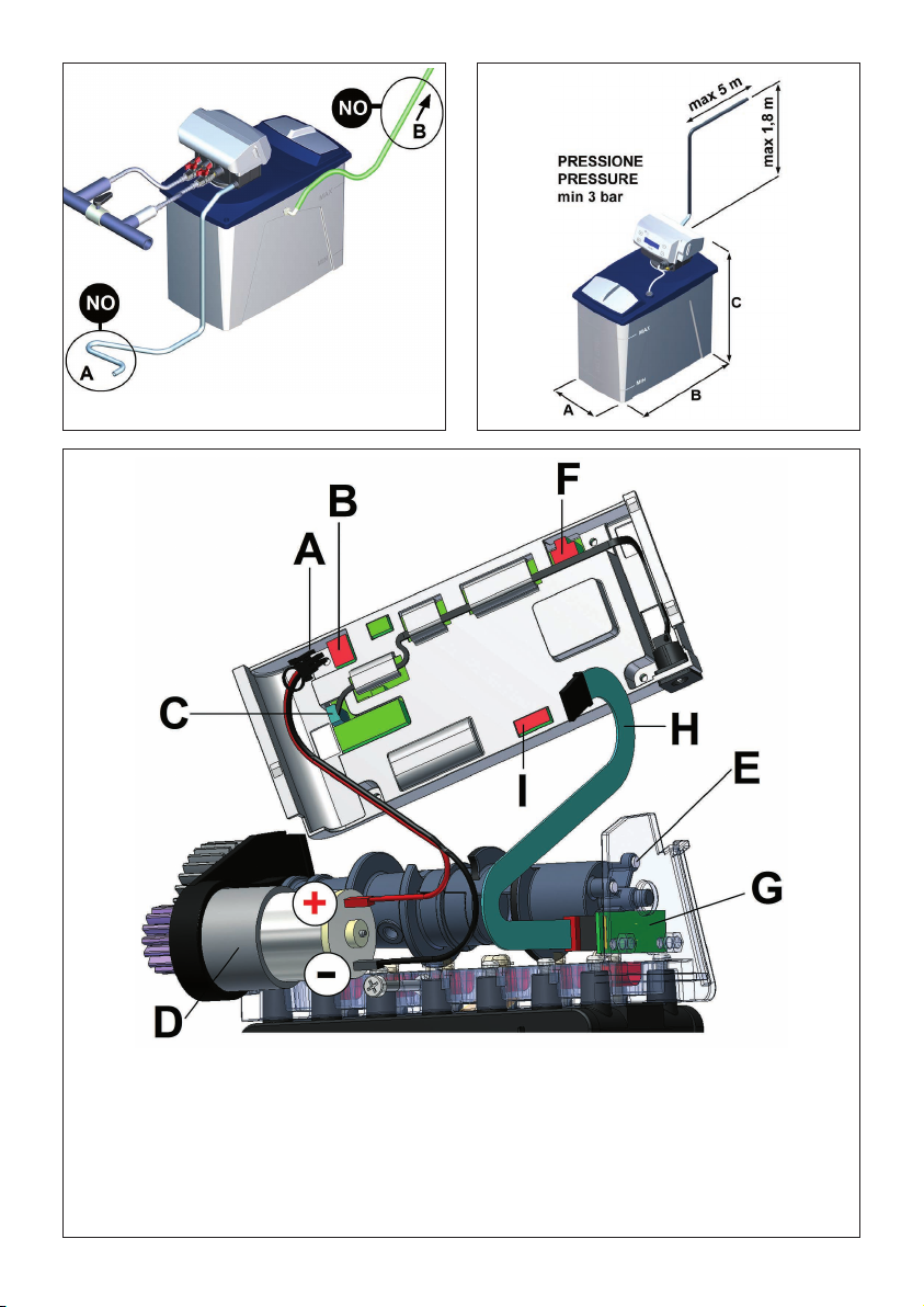
• se il punto di scarico è situato più in alto, è consentita
un’altezza massima di 1,8 metri a condizione che il tubo
non superi i 5 metri di lunghezza e la pressione della rete
sia di almeno 3 bar (fig. 5);
• accertarsi che il tubo non venga schiacciato o piegato,
l’acqua al suo interno deve scorrere senza ostacoli (fig. 4,
A);
• non collegare il tubo di scarico direttamente ad un sifone
o ad altre tubazioni di scarico, per evitare ritorni o inquina-
menti nell’addolcitore.
9.4 COLLEGAMENTO ALLA SALAMOIA
L’installatore deve controllare che il tubo ed i raccordi di col-
legamento tra la valvola e la salamoia abbiano una perfetta
tenuta, per evitare infiltrazioni d’aria (fig. 7, A).

Manuale d’istruzioni serie AL 9
ITALIANO
manuale
d’istruzioni serie AL
9.5 COLLEGAMENTO ALLO SCARICO DEL TROPPO PIENO
L’installazione della tubazione di troppo pieno (fig. 3, E) sul
tino salamoia, consentirà lo scarico di eventuali eccessi d’ac-
qua, causati da irregolari rabbocchi o da difetti di funziona-
mento.
Forare la salamoia a circa 10 cm sotto il coperchio (fig. 1, E)
con un foro da 17 mm di diametro e avvitare il raccordo di
troppo pieno.
Inserire il tubo flessibile verde in dotazione sul raccordo, quin-
di collegare il tubo ad uno scarico posto più in basso rispetto
al raccordo, poiché l’acqua che eventualmente uscirà non
sarà in pressione ( fig. 4, B).
Si consiglia di non collegare il tubo di troppo pieno nello stes-
so pozzetto dove è installato il tubo di scarico dell’addolcitore,
per evitare eventuali ritorni d’acqua in salamoia.
Completata l’installazione si può procedere con la messa in
funzione.
10) MESSA IN FUNZIONE
La messa in funzione dell’addolcitore prevede: la scelta della
lingua, la programmazione dell’ora e del giorno e lo svolgi-
mento del programma “installazione”.
ATTENZIONE: per la memorizzazione dei dati seguire attenta-
mente le istruzioni, verrà richiesto di scollegare e ricollegare
il connettore della corrente (fig. 9, A) e contemporaneamente
tenere premuti dei tasti vicino al display.
10.1 SCELTA DELLA LINGUA
È possibile scegliere una delle seguenti lingue: italiano, ingle-
se, francese, tedesco e spagnolo.
Per selezionare la lingua preferita:
- Inserire la spina (fig. 9, B) nella presa di corrente
- Inserire il connettore (fig. 9, A) nella valvola e contempo-
raneamente tenere premuti i pulsanti OK e +, finché sul
display comparirà la lingua programmata.
- Premere il tasto +e scegliere la lingua desiderata; preme-
re OK per confermare
- Staccare il connettore dalla valvola (fig. 9, A).
10.2 SCELTA DELL’ORA E DEL GIORNO CORRENTI
- Premere contemporaneamente i tasti –e +, inserire il
connettore nella valvola (fig. 9, A) finché sul display compa-
rirà il giorno della settimana lampeggiante
- Premere il tasto +e scegliere il giorno attuale, premere OK
per confermare
- Con i tasti +e –, Impostare l’ora corrente, premere OK
per confermare
- Staccare il connettore dalla valvola (fig. 9, A).
10.3 PROGRAMMA INSTALLAZIONE
Svolgere in sequenza le seguenti operazioni, per mettere in
funzione l’addolcitore:
• inserire il connettore di corrente nella valvola, (fig. 9, A) e
contemporaneamente premere il tasto –finché sul di-
splay compare la scritta “INSTALLAZIONE”
• attendere qualche secondo, dopo di che aprire lentamente
prima il rubinetto d’ingresso (fig. 3, D) e successivamente
aprire lentamente il rubinetto d’uscita (fig. 3, B)
Ora l’addolcitore, da solo, eseguirà il programma per l’instal-
lazione eseguendo le seguenti fasi:
1. controcorrente (B3)
2. primo riempimento della salamoia e lavaggio veloce (B7)
3. aspirazione e lavaggio resine (B5)
4. risciacquo rapido e secondo riempimento della salamoia
(B7),
5. esercizio
Il display mostrerà la fase in cui si trova e il tempo rimanente
per completare l’installazione.
Alla fine del ciclo, riempire per tre quarti la salamoia con il
sale (fig. 7); l’addolcitore sarà così pronto per la program-
mazione.
È possibile interrompere lo svolgimento del programma di
installazione premendo per 5 secondi il pulsante –, l’addolci-
tore si porterà in posizione di esercizio.
11) PROGRAMMAZIONE DEL TIMER
La programmazione del timer permette di impostare:
• i giorni della settimana in cui svolgere la rigenerazione, op-
pure un intervallo di giorni tra una rigenerazione e la suc-
cessiva
• l’ora in cui svolgere la rigenerazione
• il modello di addolcitore
• le eventuali modifiche dei tempi della rigenerazione
• attivare gli allarmi per segnalare l’esaurimento del sale nella
salamoia.
Prima di iniziare la programmazione vi suggeriamo di prende-
re nota del modello (fig. 3,L).
ATTENZIONE: durante la programmazione se non viene pre-
muto nessun tasto per più di 1 minuto il timer tornerà a visua-
lizzare sul display l’ora e il giorno, tenendo memorizzati i dati
inseriti fino a quel momento.
Per ritornare al punto della programmazione in cui si era arri-
vati, occorre ripetere la programmazione da capo.
11.1 AVVIO
Inserire il connettore nel timer (fig. 9, A), sul display comparirà
l’ora, il giorno, il modello dell’addolcitore (per esempio se
l’addolcitore è un AL8 comparirà -08-).
11.2 PROGRAMMAZIONE DEI GIORNI DI RIGENERAZIONE
Vi sono due modi per programmare le sequenze di rigenera-
zione: nell’arco della settima, oppure impostando un intervallo
di giorni tra una rigenerazione e la successiva.
ATTENZIONE: una programmazione escluderà l’altra, per
poter impostare l’intervallo di giorni tra una rigenerazione e
l’altra (paragrafo 11.2.2), non si dovrà selezionare nessun
giorno di rigenerazione nella programmazione settimanale
(paragrafo 11.2.1).
Si potrà comunque modificare la programmazione e passare
da una all’altra quando lo si desidera.
1) premere OK finché compare la scritta “PROGRAMMA-
ZIONE: PREMERE OK”
2) premere ancora OK . Sul display compare il giorno lampeg-
giante.
11.2.1 PROGRAMMAZIONE DELLE RIGENERAZIONI CON
PROGRAMMA SETTIMANALE
Premendo +apparirà un asterisco (per esempio *lunedì),
indicando che in quel giorno l’addolcitore farà una rigenera-
zione. Premendo ancora +l’asterisco scompare, annullando
la rigenerazione.
Premendo il tasto –si scorrono i giorni.
Programmare le rigenerazioni nei giorni desiderati dopo di che
premere OK .
Se non viene messo nessun asterisco il timer darà ora la
possibilità di impostare un intervallo di giorni tra una rigenera-
zione e la successiva (paragrafo11.2.2).
15:00 LUNEDÌ
- 08 -

11.2.2 PROGRAMMAZIONE DELLE RIGENERAZIONE CON
INTERVALLO DEI GIORNI
Nel caso si voglia impostare un intervallo di giorni tra una
rigenerazione e l’altra, non mettere nessun asterisco, ma pre-
mere OK . Sul display comparirà: “RIGENERAZIONE OGNI 01
GIORNI”.
Con +e –impostare il numero di giorni tra una rigenerazio-
ne e la successiva.
Per esempio: selezionando 12 significa che l’addolcitore effet-
tuerà una rigenerazione ogni 12 giorni.
I valori vanno da 00, nessuna rigenerazione, fino a 30, che
significa 1 rigenerazione ogni 30 giorni.
Impostando 00, l’addolcitore non effettuerà mai una rige-
nerazione automatica, ma soltanto con avvio manuale (vedi
paragrafo 13.1).
Dopo aver inserito il numero dei giorni, premere OK per con-
fermare.
11.3 IMPOSTAZIONE DELL’ORA DI RIGENERAZIONE
Dopo avere impostato i giorni per fare la rigenerazione sul
display compare la scritta “AVVIO RIGENERAZ. ORA: ora:-
minuti”
1) impostare l’ora in cui svolgere la rigenerazione con +o
–e premere OK per confermare.
2) impostare i minuti con +o –e premere OK per confer-
mare.
11.4 SCELTA DELL’ADDOLCITORE
Per il corretto funzionamento dell’addolcitore è fondamentale
che i tempi delle fasi della rigenerazioni siano in funzione della
quantità di resina contenuta nella bombola.
Maggiore è la quantità di resina, maggiore sarà il tempo per
eseguire una corretta rigenerazione.
La valvola ALIA ha memorizzato tre programmi standard: 5, 8
e 12 uno per ciascun modello.
Può succedere che durante il normale esercizio sia riscontrato
qualche carenza o malfunzionamento dovuto al programma
di default, l’installatore, in quel caso, potrà riprogrammare la
valvola creando un programma personalizzato variando i tem-
pi delle singole fasi della rigenerazione (B3, B5,B7).
ATTENZIONE: la scelta di uno dei tre modelli (5, 8,12),
escluderà la possibilità di variare i tempi di rigenerazione
(B3,B5,B7), se invece si vogliono modificare i tempi, non si
dovrà selezionare nessun modello.
Vi consigliamo, per iniziare, di scegliere l’esatto modello e poi
eventualmente, se le regolazioni di default sono inadeguate,
modificare i tempi.
Fate attenzione, in caso di errore di inserimento dei dati, si
dovrà riprendere da capo la programmazione.
Quando il display visualizza: “MODELLO 5 SI= OK NO=+”
premere OK per confermare se il modello è AL5,oppure pre-
mendo il tasto +il display visualizzerà “MODELLO 8 SI=
OK NO=+” premere OK per confermare se il modello è AL8,
oppure premendo ancora il tasto +il display visualizzerà
“MODELLO 12 SI= OK NO=+” premere OK per confermare
se il modello è AL12, oppure premendo il tasto +si passerà
alla modifica dei tempi delle singole fasi della rigenerazione
(paragrafo 11.5).
Selezionando invece uno dei modelli di default si passerà alla
programmazione dell’allarme sale (paragrafo 11.6).
TAB.1: Durata della rigenerazione e consumo d’acqua in base
al modello:
11.5 PERSONALIZZAZIONE DEI TEMPI PER LA
RIGENERAZIONE
Le fasi della rigenerazione sono:
- Esercizio
B3 - Controcorrente
B5 - Aspirazione salamoia e risciacquo lento delle resine
B7 - Riempimento e lavaggio veloce
Se nessun modello è stato selezionato ora sul display compa-
re la scritta “POS. B3 minuti: secondi”
- Impostare il numero di minuti con i tasti +o –(vedi tabel-
la TAB.2).
- Premere OK per confermare, impostare il numero di secondi
con i tasti +o –, premere OK per confermare.
Il display mostrerà: “POS. B5 minuti: secondi”, e in succes-
sione:
- Ripetere la procedura per impostare il tempo delle fasi B5 e
B7.
- si passerà alla programmazione dell’allarme sale (paragrafo
11.6).
TAB.2: intervallo dei tempi delle fasi:
Aumentando o diminuendo il tempo della rigenerazione si va-
ria in modo proporzionale anche la quantità d’acqua scaricata
necessaria per svolgere la rigenerazione.
Si consiglia di prendere i valori della tabella TAB.1 e cor-
reggerli leggermente, soprattutto il tempo della fase B7 (ri-
empimento) deve essere impostato con criterio in base al
modello di addolcitore, senza scostarsi tanto dal valore della
tabella TAB.1, perché la durata di questa fase è direttamente
proporzionale al consumo di sale e al livello dell’acqua nel
contenitore della salamoia.
11.6 DISINFEZIONE RESINE E ALLARME SALE
(MONITORAGGIO DELLA PRESENZA DI SALE)
L’addolcitore è dotato di un sistema, che durante la rigenera-
zione, disinfetta le resine.
Il dispositivo è inserito nel corpo della valvola (fig. 8, A), ha
due elettrodi che a contatto con l’acqua salata, per elettrolisi,
generano ipoclorito che andrà a contatto con le resine disin-
fettandole.
Se gli elettrodi non troveranno l’acqua salata, non potrà svol-
gersi l’elettrolisi e verrà dato un segnale sia visivo che acusti-
co, per avvertire l’utente di ricaricare il sale nella salamoia.
Questo monitoraggio sarà effettuato autonomamente durante
la rigenerazione, e in particolare nella fase B5.
Quando sul display comparirà: “ALLARME SALE” premendo
+si sceglierà se attivare oppure no l’allarme, dopo di che
premere OK .
Se si sceglie NO si escluderà il monitoraggio del sale e nes-
sun allarme verrà segnalato (il processo di disinfezione verrà
comunque effettuato), la programmazione è terminata ed il
display mostrerà la schermata di lavoro (11.7).
Se si sceglie SI il display mostrerà “SEGNALE ACUSTICO”,
10 Manuale d’istruzioni serie AL
ITALIANO
manuale
d’istruzioni serie AL
RANGE IN MINUTI
DURATA LITRI
RIGENERAZIONE SCARICATI
MOD. B3 B5 B7
MODELLO MIN MAX
AL5 1 MIN 15 MIN 40 SEC 16 MIN 40 SEC 50
AL8 2 MIN 20 MIN 1 MIN 23 MIN 80
AL12 3 MIN 25 MIN 1 MIN 40 SEC 29 MIN 40 SEC 110
B3 1 5
B5 15 50
B7 0 11

Manuale d’istruzioni serie AL 11
ITALIANO
manuale
d’istruzioni serie AL
premendo +si sceglie se attivare o no l’allarme acustico per
segnalare l’allarme sale.
Premere OK per confermare.
La programmazione è finita
Attivando l’allarme, l’assenza di sale verrà segnalata in tre
modi:
- Con un led rosso lampeggiante posto sopra al display (fig. 9,
C)
- Con la scritta sul display “AGGIUNGERE SALE”
- Con un segnale acustico intermittente
Nota: la segnalazione acustica, quando attiva, funzionerà dalle
ore 8.00 alle ore 12.00 e dalle ore 14.00 alle ore 18.00.
Per spegnere l’allarme sale:
1. ripristinare il sale nel contenitore della salamoia e attende-
re almeno 1 ora affinché esso si sciolga.
2. eseguire una rigenerazione manuale (paragrafo 13.1)
11.7 LETTURA DELLE IMPOSTAZIONI SUL DISPLAY
Di seguito sono mostrati i display con le indicazioni che la
valvola mostrerà durante l’esercizio.
Display d’esercizio con programmazione settimanale
(11.2.1)
• 15:00: ora (10.2);
• Lunedì: giorno (10.2);
• -08-: modello AL8 (11.4);
• *R*: indica che oggi l’addolcitore effettuerà una rigene-
razione.
Premendo il tasto +si potrà vedere l’ora di inizio rigenera-
zione(11.3)
Premendo ancora il tasto +si scorreranno i giorni della set-
timana e verranno mostrati i giorni con l’asterisco, che sono
stati selezionati per svolgere la rigenerazione.
Display d’esercizio con programmazione intervallo di ri-
generazione (11.2.2):
• 15:00: ora (10.2);
• Lunedì: giorno (10.2);
• -08-: modello AL8 (11.4);
• -04RIG-: mancano 4 giorni alla prossima rigenerazione
• F10: la rigenerazione verrà svolta 1 volta ogni 10 giorni
Premendo il tasto +si potrà vedere l’ora di inizio rigenera-
zione (11.3)
Nel caso il display non indichi nessun modello significa che
sono stati modificati i tempi per svolgere la rigenerazione
(11.5)
12) MANCANZA DELLA CORRENTE E
FERMI PROLUNGATI
Se manca corrente per brevi periodi non vi è nessun proble-
ma, anche in caso di assenza di corrente di alcuni giorni la
valvola mantiene in memoria i dati.
Se l’interruzione supera i 15 giorni occorre verificare la pro-
grammazione e le impostazione dell’ora e del giorno.
In caso di mancanza di corrente elettrica durante lo svolgi-
mento del ciclo di rigenerazione, la valvola mantiene in me-
moria tutti i dati, compresa la fase in cui si trovava prima di
essere interrotta.
Al ritorno della corrente la fase in corso verrà iniziata da capo.
Nel caso si fermi l’addolcitore per più giorni, al riavvio si deve
fare svolgere una rigenerazione.
13) COMANDI MANUALI
13.1 RIGENERAZIONE MANUALE
Per eseguire una rigenerazione manuale premere per 5 se-
condi il pulsante R .
All’avvio, sul display, comparirà la scritta “RIGENERAZIONE
RESINE”.
Durante la rigenerazione il display indicherà la fase in esecu-
zione e il tempo rimanente per completarla.
Per passare subito alla fase successiva, tenere premuto per
5 secondi R .
La rigenerazione si svolge in 4 fasi così chiamate:
Esercizio
B3 - Controcorrente
B5 - Aspirazione salamoia e risciacquo lento delle resine
B7 - Riempimento e lavaggio veloce
Esercizio: è la posizione di lavoro, entra l’acqua di rete ed
esce l’acqua addolcita.
B3 Controcorrente: è una fase di risciacquo,l’acqua
entra al contrario nella bombola, rimescolando e
risciacquando la resina e portando allo scarico
eventuali impurità che possono essersi depositate
all’interno dell’addolcitore durante il lavoro.
B5 Aspirazione salamoia e risciacquo lento: du-
rante la prima parte, l’acqua salata viene aspirata
e mandata a contatto con le resine insieme all’ipo-
clorito prodotto dagli elettrodi.
Al termine dell’aspirazione viene svolto un risciac-
quo lento delle resine.
B7 Riempimento e lavaggio veloce: viene manda-
ta acqua nella salamoia per sciogliere la giusta
quantità di sale che verrà usata nella successiva
rigenerazione contemporaneamente viene svolto
un ulteriore risciacquo delle resine.
Nelle fasi B3, B5 e B7 l’addolcitore scaricherà l’acqua dallo
scarico.
In fase di esercizio non scaricherà l’acqua dallo scarico.
Per l’utilizzo l’acqua viene sempre erogata, anche se è in
corso la rigenerazione.
Vedi TAB.1 paragrafo 11.4 per la durata delle singole fasi.
13.2 RITORNO IN POSIZIONE DI SERVIZIO
Per interrompere una rigenerazione e fare ritornare subito in
esercizio la valvola, premere contemporaneamente i pulsanti
OK e –.
13.3 PROGRAMMA RISCIACQUO RESINE
A volte può capitare che l’addolcitore eroghi acqua salata, il
problema può essere causato da una mancanza di pressione
idrica durante la rigenerazione, che ha impedito di eseguire un
corretto risciacquo all’addolcitore.
Grazie al programma del risciacquo resine, in pochi minuti
verrà scaricata l’acqua salata, rimasta nella bombola, permet-
tendo l’erogazione dell’acqua dolce.
Per avviare il ciclo di risciacquo: premere contemporanea-
mente i pulsanti OK e +, fino a che sul display comparirà la
scritta “RISCIACQUO RESINE”.
15:00 LUNEDÌ
- 08 - *R*
15:00 LUNEDÌ
- 08 - 04REG F10

12 Manuale d’istruzioni serie AL
ITALIANO
manuale
d’istruzioni serie AL
L’addolcitore risciacquerà le resine in controcorrente (B3) per
5 minuti, poi si riporterà in posizione di servizio.
È possibile interrompere in qualsiasi istante la fase di risciac-
quo, premendo per 5 secondi il pulsante +. L’addolcitore
interromperà il ciclo e si porterà da solo in esercizio.
Questa funzione è molto utile anche per scaricare la pressione
all’interno della bombola se si devono eseguire operazioni di
manutenzione (vedi paragrafo 16 “manutenzione per l’instal-
latore”).
14) REGOLAZIONE DELLA DUREZZA
DELL’ACQUA TRAMITE IL MISCELATORE
L’addolcitore eroga acqua priva di durezza, in alcuni casi però,
è richiesta una residua parte di durezza nell’acqua.
Il miscelatore permette ad una certa quantità d’acqua non
addolcita, di passare direttamente all’uscita, senza essere
depurata, miscelandosi con l’acqua addolcita.
La miscelazione alza la durezza dell’acqua erogata, per esem-
pio se l’acqua in ingresso ha durezza 30 °f in uscita dall’ad-
dolcitore la sua durezza, con il miscelatore chiuso, sarà di
circa 1 o 2 °f, regolando il miscelatore si potrà aumentare la
sua durezza di 5 o più gradi come sarà richiesto dall’utenza.
Avvitando la vite di miscelazione (fig. 3, M) si aumenterà gra-
dualmente la durezza dell’acqua in uscita.
È comunque da ricordare che questa operazione deve essere
svolta con cura dall’installatore, che alla fine dovrà misurare la
durezza dell’acqua erogata.
15) MANUTENZIONE PER L’UTENTE
La manutenzione per l’utente è limitata al semplice rabbocco
periodico di cloruro di sodio (NaCl, sale da cucina) in salamoia
(fig. 7), in mancanza del quale l’addolcitore non sarà in grado
di addolcire l’acqua.
ATTENZIONE: usare sale raffinato ad uso alimentare adatto
per gli addolcitori, tenere pulita la salamoia ed evitare di fare
cadere dentro sostanze o oggetti che possano compromettere
la salubrità dell’acqua erogata.
La responsabilità della carica del sale in salamoia è a
carico dell’utente.
Consigliamo di istruire l’utente, affinché sia in grado di far
svolgere la fase di risciacquo resine all’addolcitore (vedi pa-
ragrafo 13.3 ), nel caso l’addolcitore erogasse acqua salata
16) MANUTENZIONE PER L’INSTALLATORE
Per avere un funzionamento ottimale si consiglia di effettuare
periodicamente le seguenti operazioni:
- ogni 6 mesi pulire la salamoia e rimuovere eventuali sedi-
menti dal pescante (fig. 1, B);
- almeno 1 volta all’anno controllare e pulire l’eiettore (fig. 8,
B), il suo filtro (fig.8, C) e gli elettrodi (fig.8, A), seguendo le
seguenti istruzioni:
1. Chiudere il rubinetto d’entrata e d’uscita dell’acqua (fig. 3,
B, D)
2. Tenere premuti i pulsanti OK e +finché sul display com-
pare la scritta “RISCIACQUO RESINE”.
3. Attendere 30 secondi poi scollegare il connettore del tra-
sformatore dal timer (fig. 9, A).
4. Svitare i tappi (fig. 8, D) e rimuovere l’eiettore (fig. 8, B) il
filtro (fig. 8, C) ed il porta elettrodi.
5. Pulire i componenti con acqua e verificare che il foro
dell’eiettore non sia ostruito (fig. 8, B)
6. Riposizionare con attenzione i particolari nelle proprie sedi
e avvitare i tappi (fig. 8, D)
7. Lentamente aprire i rubinetti di entrata e uscita dell’acqua
(fig. 3, B, D)
8. Ricollegare la corrente (fig. 9, A)
9. Lasciare terminare il risciacquo resine (circa 5 minuti), al
termine del quale la valvola si posizionerà in fase di eserci-
zio.
17) CONSIGLI UTILI
L’esperienza ha insegnato che spesso la causa del mal fun-
zionamento degli addolcitori è dovuto ad una difettosa istal-
lazione del tubo di scarico (fig. 4, A). Per questo motivo si
consiglia una corretta installazione (fig. 3, F) e l’utilizzo del
tubo di scarico dato in dotazione.
Dove possibile, si consiglia di installare un filtro prima dell’ad-
dolcitore per eliminare sostanze che possano compromettere
il buon funzionamento dell’apparecchio.
18) SMALTIMENTO
Lo smaltimento di eventuale materiale di scarto deve essere
fatto secondo le normative vigenti.
Se si deve dismettere la macchina al momento della rimozio-
ne dall’impianto togliere il cavo di alimentazione dalla presa
elettrica e tagliarlo.
L’addolcitore è costruito con materiali non pericolosi, la mag-
giore parte sono polimeri, acciaio inossidabile e parti elettriche
ed elettroniche, occorrerà quindi smaltirli secondo le norma-
tive vigenti.
19) ALLARMI
ERROR 1
La valvola non riesce a trovare la posizione corretta.
Quando appare questa segnalazione verificare se l’albero a
camme gira o è fermo.
1. Se l’albero a camme gira:
1.1 occorre controllare se il lettore magnetico è nella corretta
posizione oppure se è guasto (fig. 6, G);
1.2 se il cavo o il connettore che collega il timer al lettore
magnetico sono collegati correttamente o se sono dan-
neggiati (fig. 6, H, I);
1.3 controllare che l’albero a camme sia montato corretta-
mente e non inclinato;
1.4 controllare se i magneti sono tutti inseriti nell’albero a
camme (fig. 6, E);
2. Se l’albero a camme non gira:
2.1 controllare se il cavo di connessione tra il motore e il
timer è scollegato o montato non correttamente (fig. 6, A,
B, D)
2.2 controllare che il motore non sia guasto o ostacolato nel
suo movimento (fig. 6, D)
ERROR 2
Questo allarme indica che il timer non è riuscito a leggere tutti
i dati del programma.
Per il ripristino dei dati, staccare il connettore della corrente
dal timer (fig. 9, A) e riattaccarlo.
Programmare nuovamente il timer con i parametri necessari
(vedi capitolo 11 “programmazione del timer”).
SOSTITUIRE BATTERIA
Questo allarme indica che occorre sostituire la batteria. Dopo
averla sostituita è necessario programmare nuovamente l’ora
(vedi paragrafo 10.2).

PROBLEMA RISOLUZIONE
Manuale d’istruzioni serie AL 13
ITALIANO
manuale
d’istruzioni serie AL
20) PROBLEMA, CAUSA E RISOLUZIONE
La valvola non rigenera automaticamente - controllare che l’alimentazione elettrica sia connessa (fig. 9, A, B) e che il
connettore della scheda elettrica sia inserito (fig. 6, C)
- verificare la programmazione
(vedi capitolo 11 “programmazione del timer”)
La valvola rigenera ad un’ora sbagliata - verificare la programmazione dell’ora attuale e dell’ora di rigenerazione
(vedi paragrafo 10.2 e 11.3).
Mancata aspirazione salamoia, - verificare che la pressione di rete sia almeno 2 bar
l’addolcitore non consuma sale - controllare che il tubo di scarico non sia ostruito o schiacciato (fig. 4, A)
- pulire iniettore (fig. 8, B) (vedi capitolo 16)
- verificare che la valvola non aspiri aria in prossimità dei raccordi (fig. 7, A)
La salamoia si riempie troppo - controllare che il tubo di scarico non sia ostruito o schiacciato (fig. 4, A)
se l’eccessivo riempimento avviene durante - verificare che la valvola non aspiri aria in prossimità dei raccordi (fig. 7, A)
la rigenerazione: - pulire iniettore (fig. 8, B) (vedi capitolo 16)
- verificare che la pressione di esercizio sia almeno 2 bar
- verificare che il modello selezionato sia corretto e, nel caso in cui il tempo
di riempimento sia stato personalizzato, verificare che la durata della fase
B7 sia entro i valori limite (vedi capitolo 11.5)
se l’eccessivo riempimento avviene durante - verificare che non ci siano perdite tra la testa e la bombola (fig. 1, C e D)
il normale servizio dell’addolcitore: -
verificare che non trafili acqua nella salamoia dal tubo della salamoia (fig. 7, A)
L’addolcitore consuma più o meno sale - verificare che il modello selezionato sia corretto e, nel caso in cui il tempo
rispetto a quanto previsto di riempimento sia stato personalizzato, verificare che la durata della fase
B7 sia entro i valori limite (vedi capitolo 11.5)
Dopo la rigenerazione l’acqua -
controllare l’alimentazione elettrica e la programmazione della valvola (vedi
non è addolcita capitolo 11)
- verificare la presenza del sale nella salamoia (fig. 7)
- controllare il corretto avvitamento della vite di miscelazione (fig. 3, M)
(vedi capitolo 14).
L’addolcitore eroga acqua salata - Il problema può essere causato da una mancanza di pressione idrica
durante la rigenerazione che ha impedito un corretto risciacquo, quindi
eseguire il programma di risciacquo delle resine (vedi paragrafo 13.3)

1) INTRODUCTION
Thank you for purchasing this AL series water softener. Please
set the machine at work only after reading this instruction ma-
nual carefully. In case of trouble, please contact your retailer
for assistance. Keep this manual for future reference.
2) HOW DOES A WATER SOFTNER WORK?
Thanks to the ionic exchange resins inside the cylinder, the
water softener traps magnesium and calcium salts dissolved
in the water, getting rid of water hardness and preventing sca-
le formation. In order to safeguard the correct functioning of
resins, it is essential that you periodically put salt in the brine
tank (fig. 7). Salt will be collected in the form of salty water
during the regeneration cycle. If there is a salt shortage in the
brine tank, the water softener will warn the user with visual
and/or acoustic signals. In addition, during the regeneration,
the water softener will also perform resins disinfection to pre-
vent the formation of bacteria.
3) SYSTEM DESCRIPTION
The main components of the water softener are:
• 1 5-cycle ALIA valve (fig. 1, C) with the following features:
- It can be programmed in 5 different languages
- With the “setting at work” program, it performs the va-
rious steps for the setting at work autonomously
- With the “resins rinse” function, the resins can be rinsed
- The resins regeneration can be performed at a precise
time and day chosen by the user
- Regenerations can be performed following a weekly pro-
gram
- Regenerations can be performed with an interval of 1 to
30 days
- Regenerations can be performed in a semi-automatic
way, only when the appropriate key is pressed
- Resins disinfection is performed during regeneration
- If a salt shortage is detected, a visual and/or acoustic
signal will warn the user
• 1 brine tank for the cylilnder and the salt (fig. 1, A)
• 1 cylinder containing the resin suitable for water softening
(fig. 1, D)
3.1 THE PACKAGING CONTAINS:
• 1 AL series water softener with ALIA valve
• 1 instruction manual
• 1 4-metre unloading pipe
• 1 overflow curved union joint
• 1.5m of pipe for the overflow
• 2 taps for water connection
• 1 test for water hardness
4) TECHNICAL DATA
Dimensions (fig. 5) AL5 AL8 AL12
A - Width [mm]: ........... 230 250 285
B - Depth [mm]:........... 360 460 405
C - Height [mm]: .......... 460 485 595
Weight [Kg]:.............. 11 12 15
Salt for regeneration [Kg] .... 0,6 1 1,5
Salt in brine tank [Kg] ....... 10 20 25
Cyclic capacity [m3 °f] ...... 22 36 50
Electricity supply: ..........
INPUT: 230V 50/60 Hz standard
120V 60 Hz optional
....................... OUTPUT: 12V AC
Feed water pressure: .......
0,2 ÷ 0,8 MPa (2 ÷ 8 bar)
Nominal throughoutput at 4 bar 1400 l/h
Room temperature: ........ 4°C - 35°C
Absorbed power: .......... 4 W
Water connection joints:
.....
3/8”G; 3/4”G; pipe Ø12 mm
(fig. 2)
5)
FEED WATER FEATURES
Feed water:
• ust be drinking and crystal clear water
• must have a temperature ranging between 6 °C and 25 °C
• must have a hardness lower than 900 ppm (90°f).
Water softeners performance according to water hardness
Water dispensed will have a hardness of about 2°f.
6) SECURITY WARNINGS
ATTENTION!
Should you not follow the following warnings, the manufactu-
rer is not responsible for any damage and/or injury caused to
people, objects or animals. This will also void any warranty.
1. 1. Installation, setting at work and maintenance must be
carred out only by a qualified personnel, well practised with
this kind of fixture and who thoroughly knows current local
safety regulations.
2. Keep the machine away from children.
3. The machine must not be used by children under the age
of 8 or by people with reduced physical, mental or senso-
rial capacities, or unexperienced people, unless they are
supervised by people responsible for their safety, or unless
they have received instructions about the correct and safe
usage of the machines and the dangers they are exposed
to.
4. Do not try to repair the machine, as you could damage it.
Always advise to qualified personnel.
5. Do note expose the machine to rain and damp.
6. Do not touch or use the machine with wet or damp hands
or feet, or barefoot.
7. Before installing the machine, make sure it is not faulty or
damaged because of transport; if in doubt, please contact
your retailer.
8. Repair and maintenance operations must be carried out
only with original spare parts.
9. This water softener only guarantees the softening of cold
drinkable water. Any other use is considered unreasonable.
7) INSTALLATION WARNINGS
1. 1. Open the package and make sure the machine is not
damaged. Any damage occurred during transport must
be notified to the seller.
2. Keep the package for some time, but make sure you
keep dangerous or small pieces of the packaging away
from children.
3. Install the machine in a dry and easily reachable place,
so that you can easily carry out maintenance and clea-
DUREZZA DELL’ACQUA - WATER HARDNESS
MODELLO
MODEL
°f 20 30 40 50 60
°d 11 16 22 28 33
ppm CaCO3 200 300 400 500 600
!
AL5 1050 700 525 420 350
AL8 1680 1120 840 672 560
AL12 2520 1680 1260 1008 840
14 Instruction manual AL series
instruction
manual AL series ENGLISH

Instruction manual AL series 15
ENGLISH
instruction
manual AL series
ning procedures. Do not install the machine in dirty and
hardly accessible places.
4. Do not install the machine in a place where there is an
evident violation of security rules and where people could
be easily injured.
5. The machine must be installed in a horizontal position.
6. To clean the machine, use a dry or a slighlty damp cloth.
7. Keep away from acid or corrosive products.
8. Make sure there is a working earthing arrangement.
9. Make sure the temperature of the place ranges between
4°C and 35°C.
10. Make sure the water is taken from a pipe where water
suitable for human use flows.
11. If necessary, install a by-pass to avoid water interrup-
tions in the event of a downtime.
12. Install a tap for outflow water collection, in order to check
water hardness.
13. Prepare the electric, water and unload systems for a
correct installation. In particular, make sure that all pipes
are not obstructed, not flattened or have too narrow el-
bows.
14. We advise you to install a filter before the machine, in
order to filter incoming water.
15. If the water softener is close to a boiler, make sure the
pipes and the water softener do not overheat; if possible,
keep at least a 3-metre piping between the outlet of the
water softener and the boiler inlet.
16. Make sure that the network maximum pressure do not
exceed 0.8 Mpa (8 bar). Otherwise, install a pressure
regulator.
The producer is not responsible for any damage and/or
injuries deriving from lack of respect of the above-men-
tioned warnings.
8) QUICK JOINTS
The pipe connections with the valve are made with quick join-
ts. To disconnect a pipe you must unload the pressure, then
press the black ring around the pipe next to the insertion, then
extract the pipe (fig. 10).
To connect the pipe again, you must simply insert it until it
stops.
9) INSTALLATION
9.1 ELECTRIC NETWORK CONNECTION
Make sure the electric network voltage is compatible with the
machine voltage 230V-50Hz.
Make sure the plug is compatible with the socket. In case of
incompatibility ask qualified personnel to replace it. They will
check the section of the cables suits the power absorbed.
This machine was built in accordance with the essential safety
requirements set by the following European regulations:
Low Voltage Directive 2006/95/CEE
Electromagnetic compatibility 2004/108/CEE.
Regulations EN 55014-1 (2006)+A1+A2, EN 55014-2
(1997)+A1+A2, EN 61000-3-2 (2006)+A1+A2, EN 61000-
3-3 (2008)
Product regulation IEC/EN 60335-1:2010 (safety of electrical
appliances for
household and similar purposes)
Homologated components UL/CSA/VDE are used.
It complies with the RoHS regulation
Installation must be carried out in accordance with the
law on electrical plants (CEI 64.8).
9.2 WATER NETWORK CONNECTION
Water network connection must be performed by qualified
personnel in accordance with the existing law and the instal-
ler’s instructions.
Make sure that:
• inlet (fig. 3, G) and outlet (fig. 3, H) pipes comply with
“Pipes for drinking water” regulations.
• water inlet pipe must have an inner diameter of at least 8
mm.
• the pressure of the water network ranges between 0.d Mpa
(2 bar) and0.8 Mpa (8 bar) – we advise you at least 3 or 4
bar.
• if pressure is higher than 8 bar, the installation of a pressu-
re reducer is required.
If the pressure is too low, malfuncioning may occur.
Install a non-return valve (fig. 3, A) (DVGW, DIN 1988 T2) on
the outlet pipe, in order to avoid any hot water returns that
may damage the water softener.
We advise you to follow the installation shown in Fig. 3, be-
cause it will allow you to use water also if you need to carry
out maintenance to the water softener.
At the end of the installation, before you open the inlet and
outlet taps, read chapter 10 “SETTING AT WORK” carefully.
9.3 UNLOADING SYSTEM CONNECTION
During regeneration, the outflow water must be conveyed
through a plastic flexible pipe (Fig. 3, F), Ø8 mm (included in
the package) and into the nearest unloading system.
Install the unloading pipe following the instructions below, as
a poor installation will cause malfunctioning:
insert the unloading pipe in the dedicated housing (fig. 2,
drain) and place the pipe in a basin, paying attention that:
• If the unloading point is placed higher than the machine,
the maximum height acceptable is 1.8 metres, provided
that the pipe is not longer than 5 metres and the pressure
of the supply water network is at least 3 bar (fig. 5);
• Make sure the pipe is not flattened or bent, as water
should flow out without running into obstacles (Fig. 4, A);
• The unloading system must never be directly connected
to a siphon or to other unloading pipes, in order to prevent
returns or pollution into the water softener.
9.4 BRINE TANK CONNECTION
The installer must make sure that the pipe and the joints con-
necting the valve and the brine tank have a perfect tightness,
in order to avoid any air infiltration (fig. 7, A).
9.5 OVERFLOW PIPE CONNECTION
Installing an overflow pipe (fig. 3, E) on the brine tank will
allow you to unload any water in excess, whose presence is
caused by irregular re-fills or malfunctioning. Pierce the brine
tank about 10 cm below the cap (fig. 1, E) making a 17 mm
diameter hole, and tighten the overflow joint.
Insert the supplied green flexible pipe on the joint, then con-
nect the pipe to an unloading system placed below the joint,
because water possibly coming out will not be under pressure
(fig. 4, B).
We advise you not to connect the overflow pipe to the same
basin as the water softener unloading system, in order to
avoid any water return to the brine tank.
10) SETTING AT WORK
To set the water softener at work you must: select your lan-
guage, set day and time and run the “setting at work” pro-

16 Instruction manual AL series
instruction
manual AL series ENGLISH
gram.
ATTENTION! In order to store the data, follow the instructions
carefully. You will have to disconnect and reconnect the power
connector (fig. 9, A) and, at the same time, you will have to
press and hold down the keys next to the display.
10.1 LANGUAGE SELECTION
You can select one of the following languages: Italian, English,
French, German and Spanish.
To select your language:
- Insert the plug (fig. 9, B) in the socket
- Insert the connector (fig. 9, A) in the valve and, at the same
time, press and hold down the OK and +keys, until you
see the programmed language on the display.
- Press the +key and select your language; press OK to
confirm.
- Disconnect the connector from the valve (fig. 9, A).
10.2 CURRENT DAY AND TIME SELECTION
- Press the –and +keys at the same time, insert the con-
nector in the valve (fig. 9, A) until the display will show the
day of the week, flashing.
- Press the +key and select the current day. Press OK to
confirm.
- Using the +and –, keys, set the current time. Press OK
to confirm.
- Disconnect the connector from the valve (fig. 9, A).
10.3 SETTING AT WORK PROGRAM
In order to set the water softener at work, perform the fol-
lowing operations in the right order:
• - insert the power connector in the valve (fig. 9, A) and
press the –key until the writing “SETTING AT WORK”
appears on the display.
• wait for a few seconds, then slowly open the inlet tap (fig.
3, D) first, and then slowly open the outlet tap (fig. 3, B)
At this point, the water softener, will run the installation pro-
gram by itself, carrying out the following operations:
1. backwash (B3)
2. first brine tank filling and quick wash (B7)
3. resin suction and washing (B5)
4. quick rinse and second brine tank filling (B7)
5. operation
The display will show the step performed and the residual
time until the end of the installation.
At the end of the cycle, fill the brine tank with salt for three
quarters (fig. 7); the water softener will be ready for the set-
tings. It is possible to interrupt the installation program by
pressing and holding down the –, key for 5 seconds; the
water softener will go to the “operation” step.
11) SETTING THE TIMER
When you set the timer, you can:
• set the days of the week when the regeneration will be per-
formed, or an interval of days between a regeneration and
the next.
• set the time when the regeneration will be performed
• set the water softener model
• set the possible regeneration times adjustments
• start the alarms to signal a salt shortage in the brine tank.
Before you start setting, we advise you to take note of the
model (fig. 3, L).
ATTENTION: if, during the setting, no key is pressed for more
than 1 minute, the timer display will show back the time and
day, storing the data inserted up to then.
To go back to the setting step you had reached, you need to
repeat the programming from the beginning.
11.1 START
Insert the connector in the timer (fig. 9, A). The display will
show the time, the day, the water softener model (for exam-
ple, if the water softener is an AL8, the writing -08- will appe-
ar on the display).
11.2 SETTING THE REGENERATION DAYS
Regeneration sequences can be set weekly or according to an
interval of days between a regeneration and the next.
ATTENTION: one setting will exclude the other, so if you want
to set an interval of days between a regeneration and the next
(paragraph 11.2.2) you must not select any regeneration day
in the weekly program (paragraph 11.2.1). You will be able
to modify the settings and switch from a setting to the other
whenever you want.
1) press OK until the writing “PROGRAMMING: PRESS OK”
appears.
2) press OK again. The display will show the day, flashing.
11.2.1 SETTING THE REGENERATIONS ON A
WEEKLY PROGRAM
If you press +an asterisk will appear (for example *Monday),
indicating that on that day the water softener will perform a
regeneration. If you press +again, the asterisk will disappe-
ar, cancelling the regeneration.
If you press the –key, you can scroll down the days.
Program the regenerations on the desired days and then
press OK .
If no asterisk is placed, the timer will now allow you to set an
interval of days between a regeneration and the next (para-
graph 11.2.2).
11.2.2 SETTING THE REGENERATIONS ON AN
INTERVAL OF DAYS
If you want to set an interval of days between a regeneration
and the next, do not place any asterisk and press OK . The
writing “REGENERATION EVERY 01 DAYS”.
Using the +and –keys, set the number of days between
the regenerations.
For example: if you select 12, the water softener will perform
a regeneration every 12 days.
Values go from 00 (no regeneration) to 30 (one regeneration
every 30 days).
If you set 00, the water softener will never perform an auto-
matic regeneration, but will need a manual start (see para-
graph 13.1).
After setting the number of days, press OK to confirm.
11.3 SETTING THE REGENERATION TIME
After setting the days for the regeneration, the writing “START
REGENERAT. TIME – TIME:” will appear on the display.
1) set the regeneration time using the +or –keys and
press OK to confirm.
2) set the minutes using the +or –keys and press OK to
confirm.
11.4 SELECTING THE WATER SOFTENER
For a correct functioning of the water softener, it is essential
that the times of the regeneration steps are set according to
15:00 MONDAY
- 08 -

Instruction manual AL series 17
ENGLISH
instruction
manual AL series
the amout of resin in the cylinder. The more the amout of
resin, the longer it will take to perform a correct regeneration.
The ALIA valve has three standard programs: 5, 8 and 12 –
one for each model.
It can occur that during normal operation due to the defau-
lt program a shortage or malfunctioning is detected, so the
installer, in that case, will be able to re-program the valve,
creating a custom program modifying the times of the single
regeneration steps (B3, B5, B7).
ATTENTION: the selection of one of the three models (5, 8,
12), will exclude the possibility to modify the regeneration
times (B3, B5, B12). If you want to modify the times, you must
not select any model.
We advise you to start by selecting the rigth model and then,
in case the default settings are inadequate, modify the times.
Be aware that if you insert incorrect data, you will have to
restart the programming from the beginning.
When the display shows the writing “MODEL 5 YES=OK
NO=+”, press OK to confirm if the model is AL5, or press
the +key and the display will show the writing “MODEL 8
YES=OK NO=+”. Press OK if the model is AL8, or press the
+key again and the display will show the writing “MODEL
12 YES=OK NO=+”. Press OK to confirm if the model is AL
12. If you press the +key again you will be able to modify
the times of the single regeneration steps (paragraph 11.5).
If you select, instead, one of the default models, you will pass
to the salt alarm setting (paragraph 11.6).
CHART 1. Regeneration duration and water consumption ac-
cording to model:
11.5 CUSTOM REGENERATION DURATIONS
Regeneration steps are:
- Operational
B3 - Backwash
B5 - Brine sucking and slow resin rinse
B7 - Refill and quick wash
If no model is selected, the writing “POS. B3 minutes: se-
conds” will appear on the display.
- Set the minutes using the +and –keys (see CHART 2).
- Press OK to confirm. Set the seconds using the +and –,
keys, press OK to confirm..
The writing “POS. B5 minutes: seconds”will appear on the
display.
- Repeat the procedure to set the duration for step B5 and
then step B7.
- At this point, you will proceed to set the salt alarm (para-
graph 11.6).
CHART 2: interval of step durations:
If you increase or decrease the regeneration duration, the
amount of water discharged – needed for the regeneration –
will vary proportionally.
We advise you to take in consideration the values shown in
CHART 1 and correct them slightly, especially the duration
of step B7 (refill), as it should be set carefully according to
the water softener model. Do not diverge too much from the
values shown in CHART 1 because the duration of this step
is direcly proportional to the salt consumption and the water
level in the brine tank.
11.6 RESIN DISINFECTION AND SALT ALARM
(MONITORING SALT PRESENCE)
The water softener is provided with a system that, during
regeneration, also disinfects the resins.
This device is inserted in the valve (fig. 8, A) and has two
electrodes that, when they come in contact with salty water,
for electrolysis, generate a hyplochlorite which will come in
contact with the resins, disinfecting them. If the electrodes
do not find salty water, electrolysis will not take place and the
machine will warn the user to reload salt in the brine tank with
a visual and acoustic signal.
This monitoring will be performed autonomously during the
regeneration, and in particular during step B5.
When the writing “SALT CHECK”appears on the display,
press +if you want to activate the check, then press OK .
If you select “NO”, salt check will not be performed and no
alarm will be activated - the disinfection process will be per-
formed anyway. The settings are done and the display will
show the operational screen (11.7).
If you select “YES”, the writing “CHIME” will appear on the di-
splay. Pressing the +key, you will be able to choose wether
to activate the chime in order to be warned about a salt shor-
tage.
Press OK to confirm.
End of settings.
When the alarm is active, salt shortage will be signaled in
three ways:
- with a red flashing led above the display (fig. 9, C)
- with the writing “ADD SALT TO BRINE TANK”
- with an intermittent chime
Please note: the chime, when active, will funcion from 8 am to
12 pm and from 2 pm to 6 pm.
If you want to turn down the salt alarm:
1. Refill the brine tank with salt and wait for at least one hour
so that it will melt.
2. Perform a manual regeneration (paragraph 13.1)
11.7 READING THE SETTINGS ON THE DISPLAY
Below, you will find the screens that will appear on the display,
with the indications that the valve will show during operation.
Operational display with weekly program (11.2.1)
• 15:00: time (10.2);
• Monday: day (10.2);
• -08-: model AL8 (11.4);
• *R*: it indicates that today the water softener will per-
form a regeneration.
Pressing the +key you will be able to see at what time the
regeneration will begin (11.3).
Pressing the +key again, you will be able to scroll down the
days of the week. The days associated with an asterisk are
the days selected for the regeneration.
RANGE IN MINUTES
REGENERATION LITRES
DURATION
DISCHARGED
MOD. B3 B5 B7
MODEL MIN MAX
AL5 1 MIN 15 MIN 40 SEC 16 MIN 40 SEC 50
AL8 2 MIN 20 MIN 1 MIN 23 MIN 80
AL12 3 MIN 25 MIN 1 MIN 40 SEC 29 MIN 40 SEC 110
B3 1 5
B5 15 50
B7 0 11
15:00 MONDAY
- 08 - *R*

18 Instruction manual AL series
instruction
manual AL series ENGLISH
Operational display with regeneration on an interval of
days (11.2.2):
• 15:00: time (10.2);
• Monday: day (10.2);
• -08-: model AL8 (11.4);
• -04RIG-: 4 days to the next regeneration
• F10: the regeneration will be performed once every 10
days
Pressing the +key you will be able to see at what time the
regeneration will begin (11.3)
If the display doesn’t indicate any water softener model, it
means that the regeneration durations were modified (11.5)
12) BLACKOUT AND LONG DOWNTIME
If a short blackout occurs, it will not cause any problem. Even
during a blackout of a few days the valve is able to store the
data.
If the blackout is longer than 15 days, all the settings, inclu-
ded day and time, should be checked.
In the event of a blackout during the regeneration cycle, the
valve stores all the data, included the step it was performing
before the interruption.
When the electricity comes back, the step interrupted will re-
start from the beginning.
If the water softener is non-operational for a few days, at the
re-start, a regeneration must be performed.
13) MANUAL SETTINGS
13.1 MANUAL REGENERATION
To perform a manual regeneration, press the R key for 5
seconds.
The writing “REGENERATION OF RESINS” will appear on
the display.
During the regeneration, the display will show the current step
and the remaining time to complete it.
To skip to the next step, press and hold down the R key for
5 seconds.
The regeneration is made up of the following 4 phases.
Operational
B3 - Backwash
B5 - Brine sucking and slow resin rinse
B7 - Refill and quick wash
Operational: when the machine is operational; network water
comes in, and softened water comes out.
B3 Backwash: it is a rinse phase. Water runs in
the cylinder upward, mixing and rinsing the re-
sins and carrying to the drain possible impuri-
ties settled inside the water softener during its
work.
B5 Brine sucking and slow resin rinse: during
the first part, salty water is sucked and sent in
contact with the resins together with the hypo-
chlorite produced by the electrodes.
At the end of the sucking, a slow resin rinse is
performed.
B7 Refill and quick wash: water is sent to the bri-
ne tank in order to melt the right amount of salt
that will be used in the next regeneration; at the
same time, a further resin rinse is performed.
During steps B3, B5 and B7 the water softener will unload
water from the drain.
When the machine is operational, water will not be unloaded
from the drain.
Also when the regeneration is progress, water is dispensed
for the user.
See CHART 1 paragraph 11.4 for the duration of every single
step.
13.2 RETURN TO THE OPERATIONAL POSITION
If you want to interrupt a regeneration and make the valve
return to the operational position, press the OK and –keys
at the same time.
13.3 RESINS RINSE PROGRAM
It may occur that the water softener dispenses salty water.
This problem can be caused by the lack of hydric pressure
during the regeneration, which prevented a correct rinse of
water softener to happen.
Thanks to the resins rinse program, in a few minutes the salty
water left in the cylinder will be unloaded, allowing soft water
to be dispensed.
In order to star the rinse cycle, press the OK and +keys at
the same time, until the writing “RESINS RINSE” appears on
the display.
The water softener will rinse the resins in backwash (B3) for 5
minutes, then will return to the operation position.
It is possible to interrupt the rinse step in any moment, pres-
sing the +.key for 5 seconds. The water softener will inter-
rupt the cycle and will return to the operation position.
This function is very useful also to unload the pressure inside
the cylinder if you need to perform maintenance operations
(see paragraph 16 “maintenance for the installer”).
14) SETTING WATER HARDNES USING
THE MIXER
The water softener dispenses soft water, devoid of hardness.
In some cases, however, a residual hardness in the water can
be important.
The mixer allows a certain amount of water to pass directly
from the inlet to the outlet of the water softener, without being
softened, and to be mixed to the softened water. This mixture
increases the hardness of the dispensed water. For example,
if the incoming water has a hardness of 30°f, when it will co-
me out its hardness will be of 1 or 2°f, with the mixer closed.
Adjusting the mixer you will be able to increase its hardnes of
5 or more degrees, according to your needs.
Uscrewing the mixer screw (fig. 3, M) you can gradually incre-
ase the hardnes of the outcoming water.
Please remember that this operation must be carried out very
carefully by the installer, who, at the end of the installation,
will also have to measure the hardness of the dispensed wa-
ter.
15) MAINTENANCE FOR THE USER
Maintenance for users only consists in refilling the brine tank
periodically with sodium chloride (NaCl, common salto), in
lack of which the water softener will not be able to soften
the water.
ATTENTION! Only use refined salt suitable for water softener;
keep the brine tank clean and pay attention not to drop sub-
stances or objects that might compromise dispensed water
15:00 MONDAY
- 08 - 04REG F10

Instruction manual AL series 19
ENGLISH
instruction
manual AL series
healthiness.
The user is responsible for refilling the brine tank with
salt.
We advise you to instruct the user, so that they can start the
resins rinse step (see paragraph 13.3) if the water softener
dispenses salty water.
16) MAINTENANCE FOR THE INSTALLER
For an ideal working, it is advisable to perform the following
operations periodically:
- clean the brine tank and remove any sediment from the
suction pipe every six months;
- check and clean the injector (fig. 8, B), its filter (fig. 8, C)
and the electrodes (fig. 8, A) at least once a year, following
the instructions reported below:
1. Close the water inlet and outlet taps (fig. 3, B, D)
2. Press and hold down the OK and +keys, until the writing
“RESINS RINSE” appears on the display.
3. Wait for 30 seconds, then disconnect the transformer con-
nector from the timer (fig. 9, A).
4. Unscrew the caps (fig. 8, D) and remove the ejector (fig. 8,
B), the filter (fig. 8, C) and the electrode holder.
5. Wash the components with water and make sure the hole
in the ejector isn’t blocked (fig. 8, B).
6. Carefully place the parts again in their seats and tighten
the caps (fig. 8, D).
7. Slowly open the water inlet and outlet taps (fig. 3, B, D).
8. Plug in the fixture (fig. 9, A)
9. Let the resins rinse end (it will take about 5 minutes). At
the end, the valve will position on the operation step.
17) USEFUL ADVICE
Experience teaches that, often, malfunctioning of water softe-
ners is caused by an incorrect outlet pipe installation (fig. 4,
A). For this reason, we advise you to perform a correct instal-
lation (fig. 3, F), using the outlet pipe provided.
Where possible, it is advisable to install a filter before the
water softener to get rid of substances that could compromise
the good functioning of the fixture.
18) DISPOSAL
The disposal of possible waste material must be performed
according with the existing law. If the machine must be disas-
sembled, during removal operations from the fixture, remove
the feeder cable from the power and cut it. The water softener
was built with non-dangerous materials, mainly polymers,
stainless steel, electrical and electronic parts. It is therefore
necessary to dispose them in accordance with the existing
laws.
19) ALARMS ON THE DISPLAY
ERROR 1
The valve can’t find the correct position. When this signals ap-
pears, check whether the cam shaft rotates or it is stationary.
1. If the cam shaft rotates:
1.1. Check whether the magnetic reader is in the correct
position or it is out of order (fig. 6, G);
1.2 Check whether the cable or the connector connecting the
timer to the magnetic reader are connected correctly or
they are damaged (fig. 6, H, I);
1.3 Make sure the cam shaft is mounted correctly and is not
inclined;
1.4 Check whether the magnets are all inserted in the cam
shaft (fig. 6, E);
2. If the cam shaft does not rotate:
2.1 Make sure the cable connecting the motor and the timer
is not disconnected or mounted incorrectly (fig. 6, A, B,
D).
2.2 Make sure the motor is not out of order or hindered in its
movements (fig. 6, D).
ERROR 2
This signal indicates that the timer couldn’t read all the data
in the program.
To refresh the data, disconnect the power connector from the
timer (fig. 9, A) and re-connect it.
Program the timer again with the necessary parameters (see
chapter 11 “Setting the timer”).
REPLACE BATTERY
This alarm indicates that the battery must be replaced. After
the replacement, it is necessary to set the time again (see
paragraph 10.2).

20 Instruction manual AL series
20) PROBLEM, CAUSE AND SOLUTION
PROBLEM SOLUTION
The valve does not regenerate automatically
- make sure that the fixture is connected to power supply (fig. 9, A, B)
and that the connector of the electronic card is inserted (fig. 6, C)
- check the settings (see chapter 11 “setting the timer”)
The valve regenerates at the wrong time - check the current time and the regeneration time settings
(see paragraphs 10.2 and 11.3).
Brine is not sucked, the water softener - make sure that network pressure is at least 2 bar
does not consume salt - make sure the unloading pipe isn’t blocked or flattened (fig. 4, A)
- clean the injector (fig. 8, B) (see chapter 16)
-
make sure the valve ins’t sucking air where there are the connections (fig. 7, A)
The brine tank fills too much - make sure the unloading pipe isn’t blocked or flattened (fig. 4, A)
If the excessive filling occurs during -
make sure the valve ins’t sucking air where there are the connections (fig. 7, A)
the regeneration: - clean the injector (fig. 8, B) (see chapter 16)
- check that operating pressure is at least 2 bar
- make sure the selected model is correct and, if the filling time was
customized, make sure that the duration of step B7 falls between
the range values (see chapter 11.5)
If the excessive filling occurs when the - make sure there are no leaks between the upper part and the cylinder
machine is operating: (fig. 1, C and D)
-
make sure water does not seep in the brine tank from the brine tank pipe (fig. 7, A)
Water softener salt consumption is higher - make sure the selected model is correct and, if the filling time was
or lower than expected customized, make sure that the duration of step B7 falls between the
range values (see chapter 11.5)
After regeneration, water is not softened -
check the power supply and the valve settings (see chapter 11)
- check the presence of salt in the brine tank (fig. 7)
- make sure the mixer screw is correctly tightened (fig. 3, M)
(see chapter 14).
The water softener dispenses salty water - This problem may be caused by a lack of hydric pressure during
the regeneration, that prevented a correct rinse to be performed.
As a consequence, start the resins rinse program (see chapter 13.3)
instruction
manual AL series ENGLISH
Other manuals for AL Series
1
This manual suits for next models
3
Table of contents
Languages:
Other DVA Water Dispenser manuals
Popular Water Dispenser manuals by other brands

Applied Membranes
Applied Membranes AA Series Operation manual

BRIO
BRIO CLBL720SC instruction manual

Aquaport
Aquaport AQP-10CS user manual

Elkay
Elkay LVRC8-BAC Series Installation, care & use manual

Lancaster
Lancaster 7-LETCT-1B Installation, operating and service manual

Kemper
Kemper 612 02 002 installation manual