manuals.online logo
Brands
  1. Home
  2. •
  3. Brands
  4. •
  5. DVB
  6. •
  7. Automobile Accessories
  8. •
  9. DVB MTO Series User manual

DVB MTO Series User manual

6400 SYCAMORE CANYON BLVD.
RIVERSIDE, CALIFORNIA 92507
855-680-9595
WWW.DV8OFFROAD.COM
PRODUCT
INSTALLATION MANUAL
MTO SERIES REAR BUMPER
(3RD GEN) 2022+ TOYOTA TUNDRA
RBTT2-04
TOOLS REQUIRED
SKILL LEVEL TIME REQUIRED
- 10mm, 16mm, 21mm Wrench
- 8mm, 10mm, 12mm, 15mm, 21mm
Socket
- 4mm Allen Bit
- HD Double Sided Tape/ Epoxy
- Zip Ties
- Painters Tape/Sharpie
- Scissors
- Needle Nose Pliers
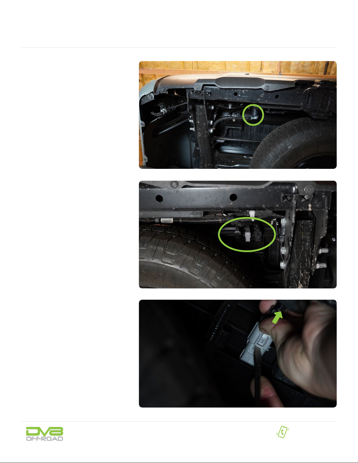
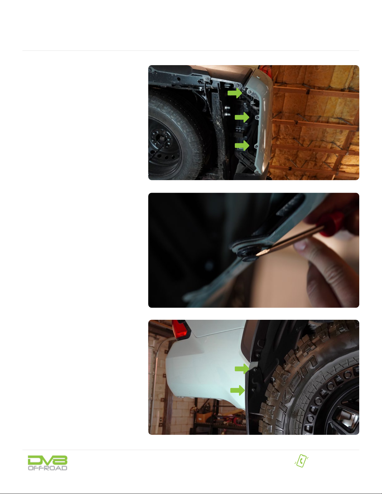
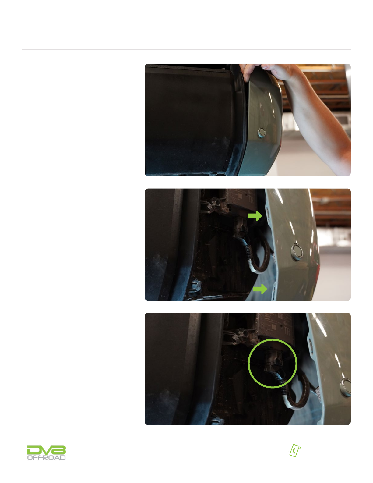
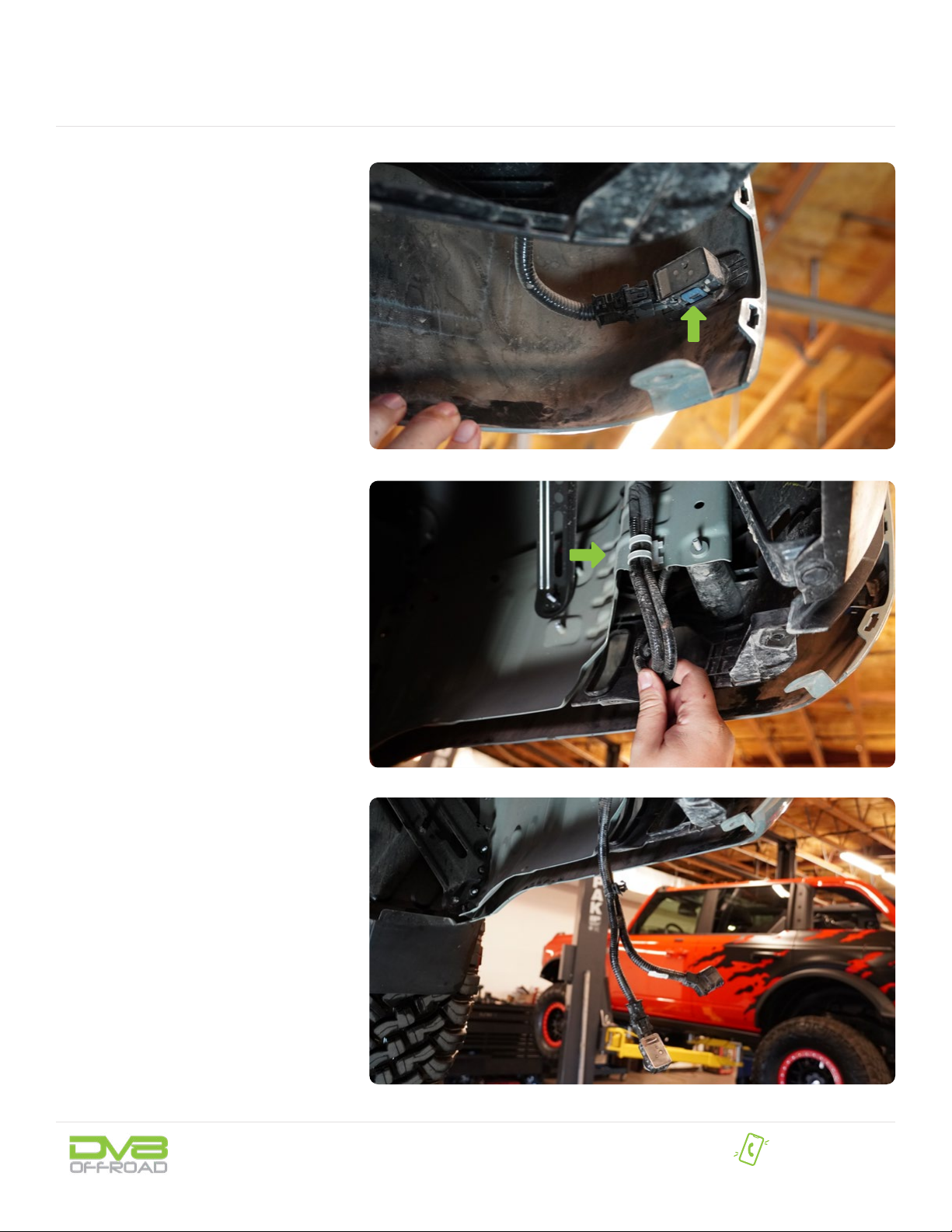
Before you install this kit — Read and understand all
instructions, warnings, cautions, and notes contained in
this installation instruction guide. Consult your vehicle
owner’s manual for proper disconnection of electrical and
lifting of vehicle if required for installation of this product.
This install may require some technical skills and
knowledge of basic mechanical work. If you do not feel that
you are capable of performing this install please take this
product to a trained professional.
After reading this guide please contact us with any
questions or concerns before installing product.
Customer Service: 855-680-9595
DV8 Offroad is not responsible for any bodily injury or harm to you
or your vehicle as a result of an improper install.
Proper installation of this kit required knowledge of the factory
recommended procedures for removal and installation of original
equipment components. We recommend that the factory shop manual
and any special tools needed to service your vehicle be on hand during
the installation. Installation of this kit without proper knowledge of the
factory recommended procedures may affect the performance of these
components and the safety of the vehicle
• Always wear eye protection when operating power tools
Inspect all contents of this package to make sure product is not damaged
and all installation hardware has been included. If parts are missing from
kit, please be prepared to provide the following information
1. Name of purchase location
2. Bar Code on side of box
3. Date above bar code
4. Date inside box cover
- Intermediate/ Difcult
- 2 to 3 persons
- 4 Hours
Time to install this should only
take about four hours.
WARNINGS/CAUTIONS BEFORE STARTING INSTALLATION
855-680-9595
NEED HELP?
Little skill level required, however,
INSTALLATION MANUAL
NEED HELP? 855-680-9595
STEP 1 | Unplug the trailer wiring
harness from the vehicle by pressing the
release tabs and pulling.
Use a trim clip tool if necessary.
STEP 2 | Unplug the three wiring
harnesses located next to the spare tire
on the passenger side using a trim clip
tool to press the release tabs and pull.
INSTALLATION MANUAL
NEED HELP? 855-680-9595
STEP 3 | Use a trim clip tool to
remove the three push pins located along
the bottom of both fenders.
STEP 4 | Use a 10mm wrench to
remove the bottom (2) bolts on the lip
of the fender securing the are to the
vehicle.
INSTALLATION MANUAL
NEED HELP? 855-680-9595
STEP 5 | Partially remove the trim
next to the bumper on the both sides of
the vehicle by gently pulling towards the
rear of the vehicle to release the clips.
When the clips are released, allow it to
hang gently to the side.
Note: Do not pull to the sides or the clips will
break. Pull towards the rear of the vehicle. Use a
trim clip tool if necessary.
STEP 6 | Unplug the wiring harness
located behind the trim on the passenger
side of the vehicle.
INSTALLATION MANUAL
NEED HELP? 855-680-9595
STEP 7 | Unplug the sensor wiring
harness from the sensors located in the
plastic trim on both sides of the vehicle.
Press the release tabs and gently pull to
unplug the wiring. use a trim clip tool if
necessary.
STEP 8 | Use a trim clip tool to
remove the clips securing the wiring
harness, and gently pull the wiring out to
prepare for bumper removal.
INSTALLATION MANUAL
NEED HELP? 855-680-9595
STEP 9 |
Remove the bumper with assistance and
set off to the side on a soft work surface
for preparation of the DV8 bumper.
Use a 22mm socket and wrench to
remove the bolts securing the bumper to
vehicle, located along both frame rails.
Note: Bumper may become loose and fall when
removing these bolts. Assistance is necessary
to prevent injury and damage to the product or
vehicle.
STEP 10 | Use a trim clip tool to
remove the clips securing the sensor
wiring harness to bumper and set it off
the to side for installation on the DV8
bumper.
INSTALLATION MANUAL
NEED HELP? 855-680-9595
STEP 11 | Remove the sensors and
bezels by gently prying with a trim clip
tool. These are held on by tape only.
Note: These sensors are location specic. Mark
the driver and passenger side sensors with
tape and sharpie for re-assembly.
STEP 12 | Use a 10mm socket to
remove the bolt securing the proximity
sensor.
INSTALLATION MANUAL
NEED HELP? 855-680-9595
STEP 13 | Remove the trailer harness
plug by squeezing the two release tabs on
each side, and pushing it out to the “rear”
of the bumper.
STEP 14 | Use a trim clip tool to
remove the clips securing the plastic trim
covers on the hitch step.
Note: These are very stiff and can be difcult
to remove.
INSTALLATION MANUAL
NEED HELP? 855-680-9595
STEP 15 | Remove the remaing top
trim pieces from the bumper using a trim
clip tool.
Squeeze the tabs underneath with needle
nose pliers if necessary where applicable.
STEP 16 | Use a trim clip tool to
remove the clips located along the bottom
lip of each side of the bumper and above
the hitch step.
INSTALLATION MANUAL
NEED HELP? 855-680-9595
STEP 17 | Remove the clips securing
the center plastic trim to the bumper
using a trim clip tool and pull up on the
trim to remove it.
STEP 18 | Use a trim clip tool to
remove the clips securing the remaining
trim pieces to the bumper.
INSTALLATION MANUAL
NEED HELP? 855-680-9595
STEP 19 | Use an 8mm socket to
remove the bolts securing the license
plate lights.
STEP 20 | Use a 12mm socket to
remove the bolts on the hitch step and
two top sections securing the trim to the
hitch.
INSTALLATION MANUAL
NEED HELP? 855-680-9595
STEP 21 | Remove all trim pieces
from the hitch.
INSTALLATION MANUAL
NEED HELP? 855-680-9595
STEP 22 | Install the trailer harness
plug by pressing it into place until the
clips are secure.
STEP 23 | If you are installing pod
lights on the bumper, do so at this time
using the hardware provided with the
lights.
Begin by unpacking all items and
inspecting for missing pieces or damage.
If you have any concens, please contact the
company the product was purhcased from.
(6) M14x45 Hex
(6) M14 Spring Washers
(6) M14 Nuts
(12) M14 Flat Washers
(4) M10x35 Hex
(4) M10 Spring Washers
(6) M10 Flat Washers
(2) M10 Nuts
(8) M6x30 Allen
(8) Nylon Lock Nuts
(16) M6 Flat Washers
HARDWARE INCLUDED
INSTALLATION MANUAL
NEED HELP? 855-680-9595
STEP 24 | Cut appropriately sized
pieces of HD double sided tape and apply
it to the side of the sensor bezels that will
contact the bumper.
Install bezels/sensors into the bumper
in the locations they were removed from
by pressing the bezel into place. Do not
press on the sensor.
Reference the painters tape/marks from
step.
STEP 25 | Install the factory license
plate lights on the bumper using a 4mm
allen bit and the provided M6x30 allen
hardware.
INSTALLATION MANUAL
NEED HELP? 855-680-9595
STEP 26 | Lay the vehicles wiring
harness across the bumper so the
sensors at their approximate location of
install.
The three wiring connectors will be
located on the passenger side of the
bumper.
STEP 27 | Install the connectors for
the license plate lights by pressing them
into place until the clips are secure.
STEP 28 | Install the wiring
connectors onto the sensors in the
bumper.
INSTALLATION MANUAL
NEED HELP? 855-680-9595
STEP 29 | Install the license plate
using the provided M6x30 allen hardware
and a 4mm allen bit.
In addition to securing the license plate,
this hardware is also used to secure the
Key fob proximity sensor on the backside
of the license plate mount.
At this time, route and secure any wiring
out of the way using zip ties.
STEP 30 | Install the provided
brackets onto the bumper as shown using
the provided M14 hardware with a 21mm
wrench and socket.
INSTALLATION MANUAL
NEED HELP? 855-680-9595
STEP 31 | Place the hitch in the
bumper between the mounting brackets
and remove the plastic mounting trim
on the bottom of the hitch to prepare the
hitch for installation on the bumper.
STEP 32 | Secure the hitch to
the mounting brackets using the M10
hardware with a 16mm wrench and
socket.
Note: If you are installing lights, do so at this
time using the hardware provided with the
lights.
STEP 33 | If you choose to apply
griptape to the top of the bumper, do so at
this time.
INSTALLATION MANUAL
NEED HELP? 855-680-9595
With assistance, lift the
bumper to the vehicle and loosely secure
it using the factory hardware and a 22mm
socket and wrench.
Bottom of the bumper should be slightly
lower than the trim panels, but sitting
evenly with the trim panels is acceptable.
Gently drop the tailgate and check that
the tailgate does not contact the bumper.
If the tailgate touches the bumper or it
is sitting above the trim line the bumper
must be adjusted.
To adjust, push up on the mounts from
udnerneath, while a friend pulls down
on the bumper to “roll” the bumper
backwards.
Finish securing the hardware once
-There is sufcient clearnace between the
bumper and dropped tailgate
-The bottom of the bumper sit ush with,
or below the trim panels.
INSTALLATION MANUAL
NEED HELP? 855-680-9595
STEP 34 | Use a trim clip tool to
remove the clip securing the trailer plug
wiring harness, then connect the harness
to the plug by pressing it into place.
STEP 35 | Install the three wiring
connectors located above the spare tire
on the passenger side of the vehicle by
pressing them into place until the clips
are secure.
INSTALLATION MANUAL
NEED HELP? 855-680-9595
STEP 36 | Connect the sensor wiring
harnesses to the sensors on the vehicle
trim on both sides of the vehicle.
Then, secure the trim panels by gently
pressing it into place until the clips are
secure.
STEP 37 | Install the factory push
clips running along the bottom lip of both
fenders.

Other manuals for MTO Series

2

This manual suits for next models

1

Other DVB Automobile Accessories manuals

DVB FBTT2-04 User manual

DVB

DVB FBTT2-04 User manual

DVB ABBR-03 User manual

DVB

DVB ABBR-03 User manual

DVB RRJL-02 User manual

DVB

DVB RRJL-02 User manual

DVB FBTT1-01 User manual

DVB

DVB FBTT1-01 User manual

DVB FBJL-07 User manual

DVB

DVB FBJL-07 User manual

DVB COMP Series User manual

DVB

DVB COMP Series User manual

DVB CMBR-01 User manual

DVB

DVB CMBR-01 User manual

DVB HDJL-02R User manual

DVB

DVB HDJL-02R User manual

DVB SPJL-02 User manual

DVB

DVB SPJL-02 User manual

DVB STJL-04 User manual

DVB

DVB STJL-04 User manual

DVB LBJL-04 User manual

DVB

DVB LBJL-04 User manual

DVB DMJL-01 User manual

DVB

DVB DMJL-01 User manual

DVB LBBR-05 User manual

DVB

DVB LBBR-05 User manual

DVB RRTT2-01 User manual

DVB

DVB RRTT2-01 User manual

DVB CCGX-01 User manual

DVB

DVB CCGX-01 User manual

DVB FBGX-01 User manual

DVB

DVB FBGX-01 User manual

DVB MPGX-03 User manual

DVB

DVB MPGX-03 User manual

DVB FBJL-11 User manual

DVB

DVB FBJL-11 User manual

DVB LPBR-03 User manual

DVB

DVB LPBR-03 User manual

DVB OFFROAD BRSB-01 User manual

DVB

DVB OFFROAD BRSB-01 User manual

DVB FBJL-06 User manual

DVB

DVB FBJL-06 User manual

DVB FS-15 User manual

DVB

DVB FS-15 User manual

DVB SRGL-09 User manual

DVB

DVB SRGL-09 User manual

DVB RRBR-02 User manual

DVB

DVB RRBR-02 User manual

Popular Automobile Accessories manuals by other brands

bp pulse home user guide

bp

bp pulse home user guide

Sirio Antenne IN-GLASS W-LAN installation manual

Sirio Antenne

Sirio Antenne IN-GLASS W-LAN installation manual

Dectane MODULITE Instruction

Dectane

Dectane MODULITE Instruction

Thule 1423 Fitting instructions

Thule

Thule 1423 Fitting instructions

CARRYBOY CB-796IG2-CIGD-R installation manual

CARRYBOY

CARRYBOY CB-796IG2-CIGD-R installation manual

Feniex T3 instruction manual

Feniex

Feniex T3 instruction manual

MTM MTM750 installation guide

MTM

MTM MTM750 installation guide

INDIWORK IW04A-N instruction manual

INDIWORK

INDIWORK IW04A-N instruction manual

Safe Fleet PRIME DESIGN FBM-1029-BLK manual

Safe Fleet

Safe Fleet PRIME DESIGN FBM-1029-BLK manual

Alpine i509-WRA-JK installation manual

Alpine

Alpine i509-WRA-JK installation manual

TEINHOF C-270 FITTING AND OPERATION MANUAL

TEINHOF

TEINHOF C-270 FITTING AND OPERATION MANUAL

Brink 5041 Fitting instructions

Brink

Brink 5041 Fitting instructions

Sunit fd user guide

Sunit

Sunit fd user guide

Circontrol CCL-PT3 SMART installation manual

Circontrol

Circontrol CCL-PT3 SMART installation manual

Brink 3615 Fitting instructions

Brink

Brink 3615 Fitting instructions

Directed Directechs DB3 installation guide

Directed

Directed Directechs DB3 installation guide

Kuda-Phonebase 084400 Installation instruction

Kuda-Phonebase

Kuda-Phonebase 084400 Installation instruction

AMiO BF Series user manual

AMiO

AMiO BF Series user manual

manuals.online logo
manuals.online logoBrands
  • About & Mission
  • Contact us
  • Privacy Policy
  • Terms and Conditions

Copyright 2025 Manuals.Online. All Rights Reserved.