DVIGear DVI-7365 User manual

User Guide
4K HDMI Fiber Optic Extender, 1x LC
DVI-7365

TABLE OF CONTENTS
SECTION PAGE
PRODUCT SAFETY ....................................1
PRODUCT LIABILITY STATEMENT. . . . . . . . . . . . . . . . . . . . . . . . 1
1.0 INTRODUCTION ...................................2
2.0 SPECIFICATIONS ..................................3
3.0 PACKAGE CONTENTS ..............................5
4.0 CONNECTING THE HARDWARE......................5
5.0 OPERATING THE UNIT.............................12
6.0 TROUBLESHOOTING ..............................14
7.0 LIMITED WARRANTY ..............................15
8.0 REGULATORY COMPLIANCE .......................15

-1-
WARNING – Product Safety
1. Do not dismantle the product housing or modify the printed circuit board
module as this may result in electrical shock or burn.
2. Do not attempt to service this product yourself as opening or removing the
product housing may expose you to dangerous voltages or other hazards.
Refer all servicing to qualied service personnel.
3. Keep this product away from liquids. Spills into the product housing may
result in re, electrical shock, or equipment damage. If liquid spills into the
housing, unplug the product immediately. Have the product checked by a
qualied service engineer before using it again.
4. Place the product in an even and stable location. If the product falls or is
dropped, it may cause an injury and/or malfunction.
5. Avoid exposing the product to extreme temperatures or to high humidity
levels as this may result in damage to the product.
6. Only use the supplied External AC Power Adapter. The use of other power
adapters may cause this product to fail or may cause a re.
7. Do not twist or exert excessive force on the ends of the connected cables
as this can cause them to malfunction. Take precaution to ensure that all
connected cables are not forced to bend beyond their minimum bend radius.
8. WARNING: Invisible Laser Radiation. Do not view directly with optical
instruments or look into beam.
Product Liability
Every effort has been made to ensure that this product is free of defects.
DVIGear cannot be held liable for the use of this product or for any direct or
indirect consequential damages arising from its use. It is the responsibility of
the users of this product to check that it is suitable for their requirements and
that it is installed correctly.
DVIGear, Inc. is the owner of numerous trademarks, both registered and
unregistered, including without limitation, the following marks: DVIGEAR®,
DISPLAYNET®, DISPLAYNET SERVER®, DISPLAYNET MANAGER®, N/AV
Design®, HYPERLIGHT® and, WILDCAT®.
The terms HDMI, HDMI High-Denition Multimedia Interface, and the HDMI
Logo are trademarks or registered trademarks of HDMI Licensing Administrator,
Inc. All other third-party trademarks used herein are the properties of their
respective owners.
© 2022 DVIGear, Inc. All rights are reserved. No part of this manual may be
reproduced or transmitted by any form or means, electronic or mechanical,
including photocopying, recording or by any information storage or retrieval
system, without the prior written consent of DVIGear.

-2-
1.0 INTRODUCTION
The DVI-7365 is a high-performance, cost-effective, 4K Multiport Optical
Extender designed to meet and exceed even the most demanding system
requirements. It supports a wide array of signal types with or without HDCP
content protection, provides long-distance extension over a single ber cable,
and supports ultra-high resolutions up to 4K (UHD) at 60Hz (4:4:4).
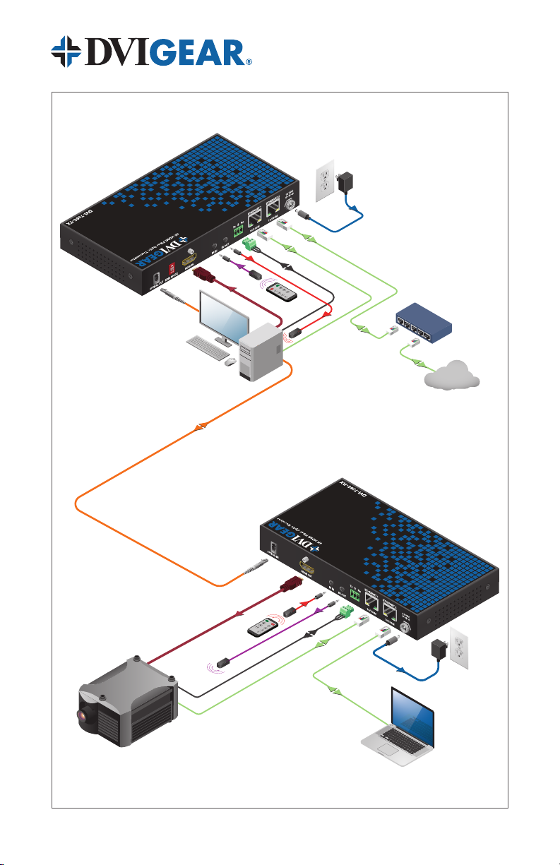
This multiport optical extender supports uncompressed HDMI 4K /60p,
embedded audio, bi-directional IR, RS 232 and two 10/100 BaseT Ethernet
ports, using only a single ber optic cable. It can extend these signals over cable
distances of up to 1.86 mi. (3,000 meters). For added versatility, these units
provide Advanced EDID Management with four operating modes: Pass-through,
Learn 1, Learn 2, and Factory Default.
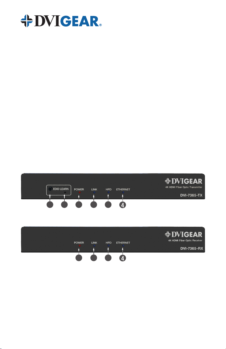
Each extender set consists of an optical transmitter unit and an optical receiver
unit. The transmitter converts the AV signals into light pulses for transmission
over a single strand of Multi-Mode or Single-Mode ber optic cable. The
receiver converts the light pulses back to AV signals for the display, as well as
other downstream devices. By using advanced ber optic technology, without
any compression, this product provides superior picture quality over greater
distances than other extension methods, such as copper cables or CAT-X
extenders. Together, these features make the DVI-7365 the ideal, cost-effective
solution for system designers and integrators who need to support high
resolution HDMI signals over extreme distances with awless image quality.
1.1 Features
The DVI-7365 offers several exceptional features:
• Supports resolutions up to 4096x2160/60p (4:4:4), without using
compression
• Extends HDMI, Ethernet (10/100Base-T), RS-232, and bidirectional IR
over a single strand of ber optic cable
• HDCP 1.4 and HDCP 2.2 compliant
• Maximum extension distances:
Single-Mode Fiber: > 1.86 miles (~ 3,000 m)
OM3 Multi-Mode Fiber: > 1,000 feet (~ 300 m)
• Four Advanced EDID Management Modes: Pass-through, Learn 1,
Learn 2, and Factory Default
• Optical ber transmission is immune to environmental signal noise
• Low RFI / EMI prole for sensitive applications
• Locking DC power connectors for added security and reliability
• Heavy-duty mounting brackets are included

-3-
2.0 SPECIFICATIONS
Performance
Standards Compliance HDMI 4K /60p, DVI v1.0, HDCP v2.2
Maximum Pixel Clock Frequency 600 MHz
Maximum Video Bit Rate 6 Gbps. / 18 Gbps. (Aggregate)
Total System Jitter (I/O) 0.6 UI maximum
Inter-Channel Skew 2 nanoseconds maximum
Ethernet 10/100 BaseT
Supported Color Depth Up to 12-bit per pixel
Supported Resolutions Up to 4K: 4096 x 2160 /60Hz (4:4:4)
Digital Audio Support Embedded HDMI digital audio up to 8-channel (7.1) LPCM, 48 kHz,
24-bit audio capability
Connections
HDMI Input / HDMI Output 1 ea. 19-pin Female HDMI connector
Optical 1 ea. LC ber optic connector
Ethernet 2 ea. RJ-45 female connector
RS-232 1 ea. 3-pin Phoenix connector
IR Input / IR Output IR IN: 1 ea. 3.5mm stereo mini-jack
IR OUT: 1 ea. 3.5mm mini-jack
Power 1 ea. Screw-Locking 2.1 / 5.5 mm female connector
Controls
TX Unit
Front Panel: EDID Learn button, LEDs for EDID, Power, Optical Link,
HPD and Ethernet
Back Panel: EDID Mode selection via 2x DIP switches
RX Unit LEDs for Power, Optical Link, HPD and Ethernet
Optical
Optical Technology CWDM (Course Wavelength Division Multiplexing) using 6 optical
wavelengths
Laser Diodes 1270 / 1290 / 1310 / 1330nm 10Gbps CWDM DFB Lasers
1490nm / 1550nm 2.5Gb/s CWDM DFB Lasers
Photo Diodes 1100 – 1620nm PIN Photo Detectors
WDM Filter Integrated 1270nm / 1290nm / 1310nm / 1330nm / 1490nm /
1550nm lter
Optical Wavelengths /
Actual Data Rates
TMDS Signals: 1270nm / 1290nm / 1310nm / 1330nm = 6.0 Gbps.
DDC, IR, RS-232, Ethernet Signals: 1490nm / 1550nm = 1.25 Gbps.
Optical Link Power Budget 8.0 dB (minimum)
Cable
Maximum Cable Length
(typical)
9/125μ Single-Mode Fiber: > 1.86 miles ( ~ 3,000 meters)
50/125μ OM3 Multi-Mode Fiber: > 1,000 ft. ( ~ 300 meters)
DVIGear Fiber Cable OFNP, Plenum rated – additional data and custom lengths available
on request
Cable Jacket OFNP, Plenum rated, Black PVC Jacket
Cable Outside Diameter 0.2" (4.4 mm)

-4-
2.1 Specications (Continued)
DDC Support
EDID Management / Modes
EDID Pass-through (transparent)
EDID Learn 1 / Learn 2 (cached)
Factory Default EDID (1080p 2-Ch audio)
HDCP Support Supports HDMI signals with or without HDCP encryption
Mechanical
Case Dimensions (H x W x D) Without Brackets: 1.0” x 7.5” x 3.9” (26.0 mm x 190.0 mm x 99.5 mm)
Width with Brackets: 8.5" (215.5 mm)
Weight TX Unit: 568g / RX Unit: 563g
Construction High-impact metal enclosure with jet black nish
Mounting Options Mounting Brackets are included
Environmental
Operating Temperature 14° to +158° F (-10° to +70°C)
Storage Temperature -40° to +185° F (-40° to +85°C)
Operating / Storage Humidity 5% to 80% (non-condensing); 5% to 95% (non-condensing)
Power Requirements
Optical Transmitter / Receiver Both TX and RX units must be powered by the supplied external
power adapters
External AC Power Adapters Model No: DVI-7216-PS
Input: 100-240VAC / 50-60Hz 0.8A; Output: 12VDC, 2.0A
Maximum Power Consumption DVI-7365-TX: 530 mA (6.4 watts); DVI-7365-RX: 450 mA (5.4 watts)
Regulatory Approvals
Fiber Optic Extender Unit FCC Class B, CE, RoHS
Laser US-FDA CDRH Class 1
External ACPower Adapters FCC, CE, UL, C-UL, BSMI, CB, CCC, LVD, LPS, PSE, RCM, RoHS, WEEE
Warranty
Limited Warranty 3 Years Parts and Labor
Model Numbers
DVI-7365-TX 4K HDMI Fiber Optic Transmitter, 1x LC
DVI-7365-RX 4K HDMI Fiber Optic Receiver, 1x LC
DVI-CUST-OPT Custom Fiber Optic Cable, Plenum rated,
Specify: Length, Fiber Type (MMF, SMF) and Optical Connector (LC)
Accessories Included
(2-1) Optional Accessories
1x External ACPower Adapter (DVI-7216-PS) with USA plug
1x User Guide
1x 3-Pin Phoenix Connector (Phoenix p.n. 1840379)
1x IR Transmitter (DVI-7360-IR-TX) (ships with DVI-7365-TX)
1x IR Receiver (DVI-7361-IR-RX) (ships with DVI-7365-RX)
2x Mounting Brackets with Screws
External AC Power Adapter (p.n. DVI-7216-PS)
with Euro, UK, or Australia plugs
+12 VDC Power Distribution Unit
(p.n. DVI-7520-PDU)
Custom Optical Cables (contact DVIGear
for details)
Note 2-1: The Transmitter and Receiver Units are sold separately.
The accessories shown here are included per unit.

-5-
3.0 PACKAGE CONTENTS
Before attempting to use this unit, please check the packaging and make certain
the following items are contained in each shipping carton:(3-1)
• 1x Transmitter (DVI-7365-TX) or Receiver (DVI-7365-RX) unit
• 1x User Guide
• 1x External AC Power Adapter (+12 VDC)
• 1x 3-pin 3.5mm Pitch Phoenix Connector (Phoenix p.n. 1840379)
• 1x IR Transmitter (with TX Unit) or IR Receiver (with RX Unit)
• 2x Mounting Brackets (attached to units)
• 4x Rack Mounting Screws
Note 3-1: The Transmitter and the Receiver Units are sold individually. Please retain the
original packing material should the need ever arise to return the unit. If you nd any items
are missing, contact your reseller or DVIGear immediately. Please have the Model Number,
Serial Number, and Invoice Number available for reference when you call.
4.0 CONNECTING THE HARDWARE
An extension set consists of a Transmitter Unit and a Receiver Unit. Please see
the following photos for information on the connections and controls.
Transmitter Unit (DVI-7365-TX) – Front View
Receiver Unit (DVI-7365-RX) – Front View
1 Power LED: Lights red when power is applied.
2 Link: LED lights blue whenever an operational ber link is present.
3 Hot Plug Detect (HPD) LED: Lights blue on both the TX and RX when
a Monitor is connected to the RX and a ber link is present.
4 Ethernet LED: Lights blue to indicate Ethernet trafc.
5 EDID LED (TX Only): See section 5.0 for details on this LED.
6 EDID Learn Button (TX Only): See section 5.1 for details on learning an EDID.
3
1
2
5
6
3
1
2

-6-
Transmitter Unit (DVI-7365-TX) – Rear View
Receiver Unit (DVI-7365-RX) – Rear View
1 Optical Output Connector (TX): Connect a Single-Mode or Multi-Mode
Fiber Optic Cable. The DVI-7365-TX uses LC optical connectors.
1 Optical Input Connector (RX): Connect a Single-Mode or Multi-Mode
Fiber Optic Cable. The DVI-7365-RX uses LC optical connectors.
2 EDID DIP Switch (TX): See Section 5.0 for details on settings.
3 HDMI Input (TX): Connect to an HDMI source.
3 HDMI Output (RX): Connect to an HDMI display.
4 Infrared (IR) IN: Connect the included IR receiver to accept IR signals
for transmission over the ber link. See Section 4.2 for further details.
4 Infrared (IR) OUT: Connect the included IR transmitter to accept IR
signals over the ber link and output them to a peripheral device. See
Section 4.2 for further details.
5 RS-232: 3-pin female Phoenix Connector for serial data pass-through.
6 LAN Ethernet Ports: Extends 10/100Base-T network connectivity over
the ber link.
7 +12 VDC Power Input: Locking female connector for AC Power Adapter.
3
1
2
5
7
6
3
1
5
7
6
3

-7-
1x Multi-Mode or Single-Mode
LC Optical Cable
+12V Power
Supply
LAN
LAN
RS-232
IR Tx
IR Rx
HDMI
4K Projector
DVI-7365-RX
HDMI
IR Rx
LAN
LAN
Ethernet Switch
LAN
Internet
RS-232
IR Tx
Control PC
+12V Power
Supply
DVI-7365-TX

-8-
4.1 Installation Instructions
1. Mount the Transmitter and Receiver Units as needed using the provided
Mounting Brackets. See section 4.3 for more information.
2. Connect the Transmitter to the HDMI output port of the signal source
(e.g. PC) using a high quality HDMI cable.
3. Connect the Receiver Unit to the HDMI input port of a destination device
(e.g. digital display) using a high quality HDMI cable.
4. Connect an LC ber optic cable (single strand of either Multi-Mode Fiber
or Single-Mode Fiber) between the Optical Output port on the Transmitter
Unit and the Optical Input port on the Receiver Unit.(4-1)
5. Connect other peripheral devices to the units as needed (see section 4.2).
6. Connect the supplied External AC Power Adapters to the power input jack
on the Transmitter and Receiver Units. Once the plug is inserted into the
jack, rotate the locking nut on the plug clockwise, until it is tight, to secure
the cable. There is no power switch on these units. The units will turn
ON as soon as the AC Power Adapter is connected to a live AC power
receptacle. In the event of a power failure, the EDID les stored in the TX
will not be affected as they are stored in non-volatile memory.
Use only the supplied power adapters to avoid the possibility of equipment
damage.
7. Apply power to the display device, then apply power to the source device.
A picture should appear on the display within a few seconds. Next apply
power to any connected peripheral devices.
Note 4-1: This product supports the use of both Single Mode Fiber (SMF), and Multi-
Mode Fiber (MMF). However, extra care is required when using SMF due to its smaller
optical aperture (8.9 microns) versus 50-60 microns for MMF. This smaller aperture means
that SMF optical cables have an increased risk of contamination due to dirt, dust, oils, etc.
that can be caused by poor handling.

-9-
4.2 Optional Connections
In addition to the video signal, the DVI-7365 supports extension of other signal
types over the ber link. These pass-through connections can be used to
provide communications with other devices in the system. These connections
include 10/100Base-T Ethernet, bidirectional IR, and RS-232.
LAN Ethernet RJ45 port
Connect to the LAN port of a peripheral device to provide a 10/100Base-T
connection via the ber link.
IR Connections
Each extender set supports bidirectional IR communications. The Transmitter
and Receiver Units each have two IR ports on the rear panel, labeled “IR IN”
and “IR OUT”. To set up the IR data pathway, connect an IR receiver device
(1x is included) to an “IR IN” port on one unit. Next, connect an IR transmitter
to the “IR OUT” port of the other unit.
Any IR communications directed to the IR receiver module on one end of the
extender set will be sent out of the IR transmitter module at the other end.
For bidirectional communication, an additional IR TX and RX (purchased
separately) may be connected. This allows IR data to be sent upstream,
downstream, or both.
Receiver
Transmitter
IR RX IR TX
IR TXIR RX
12 VDC
10/100M10/100M
ETHERNET 2ETHERNET 1
Tx Rx
IR OUTIR IN
HDMI OUT
OPTICAL IN
12 VDC
10/100M10/100M
ETHERNET 2ETHERNET 1
Tx Rx
IR OUTIR IN
HDMI OUT
OPTICAL IN
1 2
ON
1 2
ON
12 VDC
10/100M10/100M
ETHERNET 2ETHERNET 1
Tx Rx
IR OUT
IR IN
HDMI INEDID MODE
OPTICAL OUT
12 VDC
10/100M10/100M
ETHERNET 2ETHERNET 1
Tx Rx
IR OUT
IR IN
HDMI INEDID MODE
OPTICAL OUT

-10-
IR Receiver IR Transmitter
Pin Assignments
+5V Ground
VCC
IR Out
IR-
IR+
Pin Assignments
Note 4-2: For best results, it is critical to carefully position the IR Transmitter and IR
Receiver modules. The IR RX module should be placed where the user would typically aim
the remote control. The IR TX module should be placed in close proximity to the IR window
of the device being controlled. The IR TX module includes double-sided tape that can be
used to adhere it in place.
RS-232 Connections
Connect to an RS-232 device on both the Transmitter and Receiver Units to
allow serial communication to pass-through via the optical link. Please refer to
Warning 4-3 regarding wiring recommendations.
RS-232
Tx Rx
Tx
Rx
GND
RS-232
Device
Note 4-3 – WARNING: DVIGear recommends that only qualied technical personnel be
permitted to wire the Phoenix connectors as improper wiring can cause equipment damage.
For best results, it is important to use stranded wires and avoid tinning the wire ends as this
can allow them to be removed too easily from the Phoenix receptacles.

-11-
4.3 Mounting Hardware
Below Mount
Above Mount
Each Transmitter and Receiver Unit comes with a pair of Mounting Brackets to
facilitate installation on furniture or other surfaces. These Mounting Brackets
are reversible, so the unit may be installed above or below the mounting
surface. The units are shipped with the brackets installed in the “above mount”
conguration. To change the orientation of the mounting brackets, rst remove
the two screws on the sides of each bracket and set them aside. Next, ip
the mounting brackets into the desired position and screw them into the two
mounting holes located on each side of the extender units.

-12-
5.0 OPERATING THE UNIT
In most cases, the default conguration is sufcient for proper operation; however,
this extender set includes 4x EDID modes to optimize system performance.
EDID (Extended Display Identication Data) is a small data le stored in virtually
every TV, monitor and display device made over the last twenty years. This
le contains information about the display’s capabilities, such as its supported
resolutions, refresh rates, color space, type of display, manufacturer, serial
number, etc. After connecting a display to a source device, the source reads
and saves the EDID in order to determine the most suitable display parameters
(e.g. resolution and refresh rate). In this way, EDID plays an essential role in the
modern “Plug & Play” user experience.
The DVI-7365 has four (4) EDID operation modes.
EDID
Mode
DIP Switch
Conguration Description
Factory
Default
(5-1)
1
ON
2
Use the factory default EDID permanently stored
in the transmitter. The factory default EDID has a
preferred timing of 1920x1080 /60p resolution with
2-channel PCM audio, though resolutions of up to
3840x2160 may be set.
Learn
EDID 1
(5-1)
1
ON
2
Learn the EDID from the connected display to
Memory Slot 1 in the transmitter. See section 5.1 for
instructions on learning an EDID.
Learn
EDID 2
(5-1)
1
ON
2
Learn the EDID from the connected display to
Memory Slot 2 in the transmitter. See section 5.1 for
instructions on learning an EDID.
Pass-
through
(5-1)
1
ON
2
Pass-through EDID communication. In this mode,
it is possible to support live DDC and HDCP
communications.
Note 5-1: Pass-through EDID mode is the only mode that supports live DDC
communications. The extender can be set to different EDID modes by using the DIP
switches on the rear of the Transmitter Unit. The EDID LED on the front panel of the TX
Unit will change based on the current mode being used.

-13-
5.1 Learning an EDID
1. Set the EDID switch on the Transmitter to the desired EDID learning
mode (EDID Learn 1 or EDID Learn 2).
2. Connect the HDMI input on the Transmitter to the HDMI input port on
the display using a short, high quality cable.
3. First, supply power to the display. Next, supply power to the
Transmitter. The EDID LED on the front panel of the Transmitter
should light up blue. Now, press and hold the EDID button on the
front panel of the Transmitter for about 2 seconds and then release.
4. If the EDID has been successfully learned, the EDID LED will blink
once. The saved EDID le will be stored in non-volatile memory. If
the EDID learning process fails, then the EDID LED will ash 5 times.
In this case, repeat steps 1-4 above. Contact technical support if
further assistance is required.
5. Finally, disconnect the Transmitter from the display. Continue with
system setup as described in section 4.1.

-14-
6.0 TROUBLESHOOTING
If the system fails to display a signal, power OFF all devices and verify that the
following connections are properly installed:
• Ensure the Transmitter Unit is connected to the source and the Receiver
Unit is connected to the Display using high quality HDMI cables.
• The ber optic cable must be connected on both the Transmitter Unit
and Receiver Unit. Check to ensure that the optical cable is fully
inserted into the ports. Note that slight pressure on the ber optic cable
and/or connector should NOT have any inuence on the image quality of
the signal.
• The supplied External AC Power Adapters should be connected to both
the Transmitter and Receiver Units.
Once all connections have been veried, power ON the display rst, and then
the HDMI signal source.
If there is no picture or if there are intermittent picture issues, please determine
whether the Fiber Link LEDs are lit. If the Fiber Link LEDs light up, then there may
be an EDID issue. Please check to be sure the appropriate EDID mode is being
used. See section 5.0 for information on setting the EDID mode of the extender.
If the Fiber Link LEDs are not lit, then it may be necessary to check the quality
and/or condition of the ber optic cable being used. Fiber optic ports and cables
are very sensitive to dust, dirt and oil from handling. Even minute amounts of
obstructive material can interfere with or disrupt the optical transmission of the
video signals. If erratic performance or disruption is noted, it may be necessary
to have qualied technical personnel clean the optical ports and/or optical cable
using appropriate procedures and cleaning materials.
(6-1)
Note 6-1:This product supports the use of both Single Mode Fiber (SMF), and Multi-
Mode Fiber (MMF). However, extra care is required when using SMF due to its smaller
optical aperture (8.9 microns) versus 50-60 microns for MMF. This smaller aperture means
that SMF optical cables have an increased risk of contamination due to dirt, dust, oils, etc.
that can be caused by poor handling.
If the system still fails to display an image, ensure that the HDMI signal source
is compatible with the display by making a direct connection between the two,
bypassing the Fiber Optic Extender. If there is still no image, then there is a
compatibility issue between the source and the display that must be resolved.
If the problem persists after trying the above suggestions, please contact your
dealer for additional assistance. If the dealer’s technical personnel are unable
to assist you, please contact DVIGear via telephone at 1.888.463.9927 (toll-free
for United States and Canada) or 1.770.421.6699. You may contact DVIGear by
e-mail at support@dvigear.com.

-15-
7.0 LIMITED WARRANTY
LIMITED WARRANTY – Subject to the limitations stated below, DVIGear warrants
that this product will be free from defects in materials and workmanship for a
period of three (3) years from the date of purchase.
Should the product, in DVIGear’s opinion, prove defective within the warranty period
stated above, DVIGear, at its option, will repair or replace this product without
charge. Any defective parts replaced become the property of DVIGear. This
warranty does not apply to products that have been damaged due to accident,
unauthorized alterations, improper repair, modications, inadequate maintenance
and care, or use in any manner for which the product was not intended.
If repairs are necessary under this warranty policy, the original purchaser must
obtain a Return Authorization Number from DVIGear and return the product
freight prepaid to a location designated by DVIGear. After repairs are complete,
the product will be returned, freight prepaid.
The foregoing warranty is the sole and exclusive warranty given by DVIGear,
express or implied, and DVIGear disclaims all implied warranties, including but
not limited to implied warranties of merchantability or tness for a particular use.
LIMITATIONS – The liability of DVIGear with respect to any defective products
will be limited to the repair or replacement of such products. In no event shall
DVIGear be responsible or liable for any damage arising from the use of such
defective products, including but not limited to loss of use, revenue or prot,
whether such damages are direct, indirect, consequential or otherwise and
whether such damages are incurred by the reseller, end user, or any third party.
8.0 REGULATORY COMPLIANCE
This product is compliant with appropriate FCC Class B, CE, RoHS rules and
regulations. The supplied AC Power Adapters are compliant with FCC, CE, UL,
C-UL, BSMI, CB, CCC, LVD, LPS, PSE, RCM, RoHS, WEEE rules and regulations.

Your Digital Connectivity Experts
DVI-7365–UG-01 / April.2022
Toll Free 888.463.9927
Phone +1.770.421.6699
Fax +1.770.234.4207
DVIGear, Inc.
1059 Triad Court, Suite 8
Marietta, Georgia USA 30062
www.dvigear.com
This manual suits for next models
2
Table of contents
Other DVIGear Extender manuals

DVIGear
DVIGear DVI-7313 User manual

DVIGear
DVIGear DVI-7330 User manual

DVIGear
DVIGear DVI-7345 User manual

DVIGear
DVIGear DVI-7317-TX User manual

DVIGear
DVIGear DVI-7320 User manual

DVIGear
DVIGear DVI-TPS-TX95-HD User manual

DVIGear
DVIGear DVI-7350a User manual

DVIGear
DVIGear DVI-7335 User manual

DVIGear
DVIGear DVI-7370c User manual

DVIGear
DVIGear DVI-7171c User manual