Select Operation Mode:
The operating modes and ranges are controlled by a shorting
jumper on jumper block J2. This jumper block is shown in Fig. 5.
Figure 5, Mode Programming Jumpers
Jumper block J2 primary function is to control the operating mode.
There are two operating modes, Normal and Velocity. The Normal
operating mode provides for zero pressure to correspond to 0 V or
4 mA output. This mode is selected by placing the supplied short-
ing jumper for J2 on the pins next to the letter “N”. The jumper for
J2 is factory installed to the Normal Mode. If no jumper is installed
on J2, the device defaults to the “N” selection.
The Velocity mode provides the ability for the unit in conjunction
with a Pitot tube or similar flow sensor with known K factor to give
a direct output in air velocity. This mode is selected by placing the
supplied shorting jumper for J2 on the pins next to the letter “V”.
If the optional display is present, this mode prompts the display to
read in air velocity. The current or voltage output is modified such
that full scale output is 4004* K* √(ΔP) feet per minute or its met-
ric equivalent in meters per second depending upon which units
are selected. The factory programming for the K factor is 1.00 but
may be adjusted (see Adjust K Factor). The velocity displayed for
the various models can be found in Table 1.
Velocity Displayed
Model English Metric
MS-X3X K* 12.66 x 1000 fpm K* 57.7 m/s
MS-X4X K* 15.51 x 1000 fpm K* 70.7 m/s
MS-X5X K* 20.02 x 1000 fpm K* 91.2 m/s
Table 1
SETUP
Set Measurement Units:
MagnesenseTM transmitters can be easily set to operate in either
English or metric units.
The programming jumper is CONN3. A representation of this
jumper is shown in Fig. 6. English units are selected by placing the
provided shorting jumper on the lower two pins of the block. Metric
units are selected by placing the provided shorting jumper on the
upper two pins of the block. If no jumper is present English units
are selected by default.
Figure 6, Measurement Units Programming Jumper
In addition to the obvious change in the scale of the LCD display,
the full scale range and corresponding analog outputs are also
affected by the measurement units selection. The analog output
goes to full scale output (10 volts or 20 mA depending on model)
of the selected range and units. See Table 2.
FULL SCALE ANALOG OUTPUT
Model English Metric
MS-X31 10 in w.c. 2 kPa
MS-X41 15 in w.c. 3 kPa
MS-X51 25 in w.c. 5 kPa
Table 2
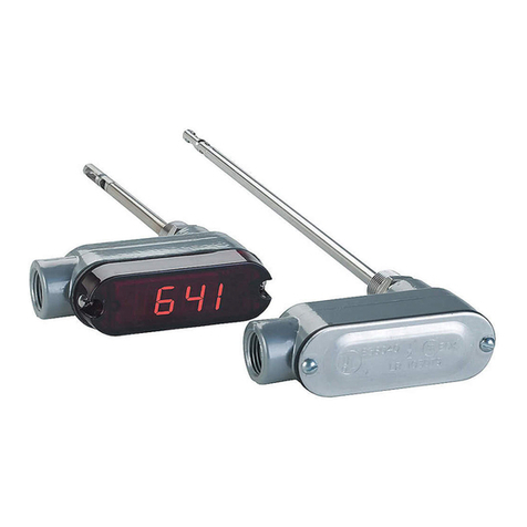
Install Optional Display:
The A-435 LCD conversion kit allows any non display model to
have the LCD added at a later time. The kit contains an LCD dis-
play and replacement cover with LCD window. The optional dis-
play may be set to read pressure either in Inches Water Column or
Kilopascal. The optional display can be also set to display air
velocity in X1000 feet per minute or meters per second when used
with a Pitot tube or similar flow sensor with a known K factor.
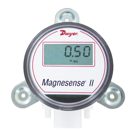
The optional display for the Magnesense®is mounted on the main
board by connectors CONN4 and CONN5. The display is proper-
ly mounted when CONN4 and CONN5 on the display are con-
nected to the corresponding CONN4 and CONN5 on the main
board. See Fig. 4. Installing the display upside down causes no
harm the display or the main board. The display just simply reads
upside down.
Label (Included with display):
The optional LCD display does not contain engineering unit indica-
tion. So that the display may be appropriately marked, four adhe-
sive labels have been provided with the units. The unit labels are
INWC, kPa, X1000 fpm, and M/S. Attach the appropriate provid-
ed units label above the display window on the cover of the device
to indicate to which units the display has been set.
Adjust K Factor:
If the optional display is present, the K factor used in velocity mea-
surements may be adjusted. This is done by activating the K fac-
tor adjustment function of the unit. To activate the K factor adjust-
ment function, take the shorting jumper from programming block
J2 and place it on the upper two terminals next to the letter “K”.
See Fig. 5. The display will now show the programmed Pitot tube
K factor. The K factor can be adjusted up and down by using the
up and down buttons as up and down buttons. Once the desired
K factor has been set, replace the shorting jumper on J2 to its
velocity position (“V”). The shorting jumper must not be left in the
“K” position for proper operation of the unit. The factory setting for
the K factor is 1.0 and it is adjustable from 0.5 to 3.
One button pressure calibration – Leaving the hose barbs vent-
ed, press and hold the “Zero/Up” switch for about 4-5 seconds.
The zero point should now be set and if the display is present, the
display will read zero. Span is also simultaneously adjusted at the
time the zero is set. No further calibration is required. It does not
matter if in metric or English unit made when performing this “one
button” calibration of both zero & span.
Bulletin A-26P
Page 3
English
CONN3
Metric
A-26P 1/9/07 2:33 PM Page 3
