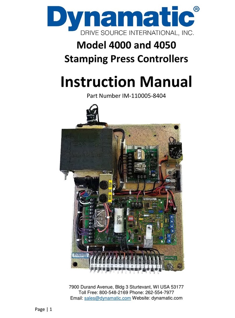
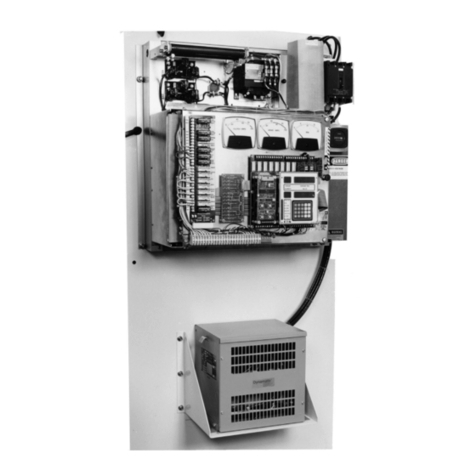
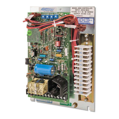
Dynamatic 4000 User manual

1
Instruction Sheet
IS-539-16 revised 2019
15-533-1016 Panel Mount 4000 (4.3 A Controller)
15-551-1016 Standard Enclosure 4000 (4.3 A Controller)
15-539-0016 Panel Mount 4050 (8 A Controller)
15-553-0016 Standard Enclosure 4050 (8 A Controller)
Model 4000 and 4050 with Dancer Position
Introduction:
These instructions relate specifically to the
following Model 4000 and 4050 controllers
which are assembled for Speed Control with
the Dancer Position modification.
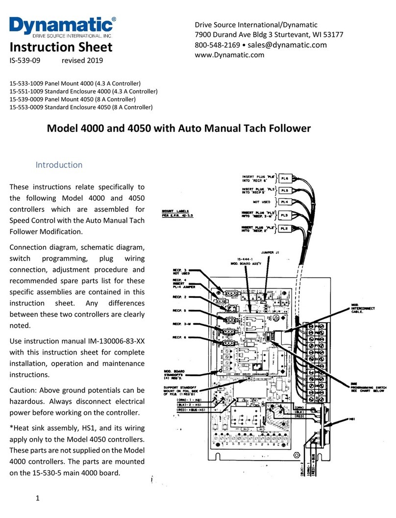
Connection Diagram, schematic diagram,
switch programming, plug wiring
connection, adjustment procedure and
recommended spare parts list for these
specific assemblies are contained in this
instruction sheet. Any differences between
theses two controllers are clearly noted.
Use instruction manual IM-130006-83XX
with this instruction sheet for complete
installation, operation and maintenance
instructions.
Caution: Above ground electrical potentials
can be hazardous. Always disconnect
electrical power before working on the
controller.
*Heat sink Assembly, HS1, and its wiring
apply only to the Model 4050 controllers.
These parts are not supplied on Model 4000
controllers. The parts are mounted on the
15-530-5 main 4000 board.
Drive Source International/Dynamatic
7900 Durand Ave Bldg 3 Sturtevant, WI 53177
800-548-2169 • sales@dynamatic.com
www.Dynamatic.com

2
Introduction: 1
Connection Diagram for Standard Enclosure 4000 Controller 3
Schematic Diagram for 4000 Controller 4
Connection Diagram 4000 Panel Mount and 4050 Controller 5
Schematic Diagram for 4050 Controller 6
Dancer Position Modification PCB 15-444-7 6
Modification PCB Mounting 7
General Description 7
Visual Inspection 7
Preliminary Adjustment 7
Main PCB 15-530-5 or 15-530-6 8
Dancer Position 8
Figure1: Trimpot Illustration 9
Adjustment Procedure 9
For Winder Operation Only 10
For Payoff Operation Only 10
Renewal Parts List 12

3
Connection Diagram for Standard Enclosure 4000 Controller
ED-58216

4
Schematic Diagram for 4000 Controller

5
Connection Diagram 4000 Panel Mount and 4050 Controller
ED-56816
Note 1: This Equipment must be installed in compliance with National electrical code and all applicable
state and local codes
Note 2: Transformer may be supplied as a winding in the ac motor or as a separate item. Standard
connections to winding in mechanical unit and loose transformer connections are both shown above.
Note 3: Dancer Position pot R5 is shown wired for winder operation. For use with payoff, pot rotation will
be reversed- rotating the Dancer Position pot R5 toward the zero (P1) and will cause the dancer to rise
Note 4: Values shown are typical. See BOM for actual values

6
Schematic Diagram for 4050 Controller
Dancer Position Modification PCB 15-444-7

7
Modification PCB Mounting
If you have purchased a complete controller this section may be passed over and you may proceed to
General Description.
1. Place the Main PCB in front of you with the long dimension in a horizontal position and the
terminal strip to the left.
2. Remove the DIP switch by pulling it straight out of the receptacle, RECP 1. Then, peel the adhesive-
backed label off the other half of RECP 1.
3. Insert the arrow-type locking head of the four nylon stand-offs supplied into the four 0.188”
diameter holes in the main PCB and press in. The tabs will snap out to lock the stand-offs
permanently in position.
4. Hold the modification PCB assembly over the stand-offs with the ribbon connector toward you
and insert the ribbon connector plug into RECP 1. Be careful to see that all 16 pins are started
properly into the receptacle before pressing the plug in.
5. Align the holes in the modification PCB assembly over the stand-offs and press over the tapered
posts until the locking flanges snap out to lock the board in position.
General Description
The Dancer Position modification converts the standard 4000 and 4050 controllers into a position control
system. The feedback quantity to the Main PCB becomes the position of a Dancer Operated
potentiometer rather than the drive output shaft velocity. The steady state position of the “dancer” is
actually controlled by adjusting the drive velocity so that a constant take-up reel, outer edge tangential
velocity, equal to the line speed, is maintained. The modification circuit includes a supplementary clutch
current bandpass filter circuit and a position rate circuit to provide the lead compensation necessary for
stability. The current gains are adjustable so that the dynamic response of a specific system can be tuned.
Visual Inspection
1. Before proceeding to the set-up procedure, check the controller for any damage that may have
occurred during shipment, such as loose connections and damaged wire or components.
2. Check all interconnection wires for conformance to connection diagram and schematic as
supplied in this instruction sheet.
3. Check the Operator’s controls (which are supplied by customer) to see if they are connected
properly per the connection diagram. This includes the Dancer Position pot R5 and the Start and
Stop pushbutton controls.
Preliminary Adjustment
Perform the following preliminary adjustments (with no power applied to the controller)
A. Operator’s Controls (supplied by customer unless specified)
1. Dancer Position Potentiometer R5

8
a. For Winder operation only, set the Dancer Position potentiometer R5 to 0% (Full CCW)
b. For Payoff operation only, set the Dancer Position potentiometer R5 to 0% (Full CCW).
c. Note location of Start and Stop pushbuttons
B. Main PCB 15-530-5 or 15-530-6
The pots used are screwdriver adjust, single turn pots. Do not use a screwdriver with a blade width
exceeding 1/8 inch.
1. Set the Accel Rate potentiometer R18 to 50%. The acceleration time range is 2-25 seconds.
The Accel Rate potentiometer controls the rate of rise of the Dancer Operated pot R55 when
the drive is first energized or when the Dancer Position pot R5 is changed during operation.
2. Set the Zero Adjust potentiometer R19 to 0% (Full CCW)
3. Set the Max Speed/Volts potentiometer R21 to 0% (Full CCW) (Not Used).
4. Set the Velocity Damping potentiometer R22 to 0% (Full CCW) (Note Used)
5. Set the Time Constant (TC) Adjust potentiometer R26 as follows (See trimpot illustration):
6. Set the Current Feedback potentiometer R20 to 0% (Full CCW) (Not Used)
Mechanical Unit Model Numbers
TC Adjust
Setting
AC/ACM/ACS/PD/VT
Fractional Hp (FHP)
AS/AT/AE/VT/EC
FHP/181/182
0%
184/186/214
14/18/112/132/140/180
15%
216/254/256/280
21/160/210
30%
320/360/440
25/27/180/225/250/280
100%
320/360/440
100%
*Typical product number stamped on mechanical unit nameplate:
1. A1-100214-0053, specific mechanical model is AC-214
2. B2-100210-0008, specific mechanical model is AS-21
C. Dancer Position Mod PCB 15-444-7
1. Set the Velocity Damping potentiometer R21 to 25% CW
2. Set the Current Damping potentiometer R22 to 50% CW
3. Set the Bias potentiometer R23 to 0% (Full CCW)
4. Set the TC adjust potentiometer R24 as follows (see trimpot illustration):
5. Set the Lin Accel switch SW2 to the OFF position
Mechanical Unit Model Numbers
TC Adjust
Setting
AC/ACM/ACS/PD/VT
Fractional Hp (FHP)
AS/AT/AE/VT/EC
FHP/181/182
0%
184/186/214
14/18/112/132/140/180
15%
216/254/256/280
21/160/210
30%
320/360/440
25/27/180/225/250/280
100%
320/360/440
100%

9
*Typical product number stamped on mechanical unit nameplate:
1. A1-100214-0053, specific mechanical model is AC-214
2. B2-100210-0008, specific mechanical model is AS-21
Figure1: Trimpot Illustration
D. The Dancer Operated potentiometer R55 is located externally to the controller and operator
station and is driven by a moveable dancer roll.
Adjustment Procedure
Do not have material attached to winding roll for this procedure.
Note: The following procedure is for vertical motion dancers. For horizontal motion dancers on both
winders and payoffs, the maximum storage position would correspond to the extreme low end of travel
on a vertical motion dancer.
For Winder Operation: The Dancer Operated potentiometer must be at the extreme low end of travel.
For Payoff Operation: The Dancer Operated potentiometer must be at the extreme high end of travel.
1. Using a voltmeter on the 0-10 Vdc range, connect the meter leads to terminals – P1 and test
point +TP1 on the modification PCB.
2. Start the motor and apply power to the controller.
3. Adjust the Bias potentiometer R23 CW on the 15-444-7 modification board until a zero
reading is obtained on the meter. Remove and disconnect the meter.
4. Connect a voltmeter on the 0-50 Vdc range to clutch leads -C1 and +C2. Depress the Start
pushbutton. Caution: The drive may rotate.
5. Turn the Zero Adjust potentiometer R19 CW until the needle starts to deflect; then back off
CCW until the reading is just zero. Remove power and disconnect the meter.
Zero Adjust R19 with LED monitor- Slowly increase the Zero Adjust Pot R19 CW while
monitoring the LED, D22. When the controller output is turned ON or clutch voltage is turned

10
ON (or the drive shaft begins to rotate), the LED should start flashing. Now just back off slowly
until the flashing stops. Remove power.
6. For Winder Operation Only:
a. Connect a voltmeter on the 0-10 Vdc range to the Dancer Operated pot R55 terminals -
P1 and +P7. Apply power to the controller. With the dancer at the bottom of its travel,
the meter should read zero volts. Raise the dancer to the top of its travel. The meter
should read approximately 9 Vdc. If these readings are not obtained, check for slippage
of the Dancer Operated pot. Adjust pot linkages if required until these readings are
obtained.
b. Raise the dancer roll to the desired running height and hold it in this position.
c. Connect a voltmeter on the 0-50 Vdc range to clutch coil leads -C1 and +C2. Press the
Start pushbutton. The meter should read zero. Adjust the Dancer Position pot R5 CW until
the meter starts to deflect. Then back off until a zero reading is obtained.
d. Push the Stop pushbutton. Place SW2 in the Lin position.
e. Thread the material through the machine with the dancer lowered.
f. Start the controller with the Start pushbutton.
g. The dancer should rise to midpoint of its travel without overshooting and should be stable
at this point. If the dancer is unstable, increase the setting of the Current Damping pot
R22 CW.
h. Start the main drive. The dancer should drop slightly, and then recover and rise to its set
point. If the dancer drops too low and then overshoots, increase the setting of the
Velocity R21 slightly. Important Note 1: Under normal Dancer Position Operation the
Velocity Damping setting should not be set at more than half the Current Damping setting.
Some critical systems may require higher settings, but care should be taken when doing
so. Higher than required Velocity Damping setting can cause unstable operation.
If the dancer drops but does not quickly recover, the Current Damping pot R22 may be
set to high. Decrease the setting as required.
i. After the dancer has been critically damped (minimum drop with no overshoot), run the
machine at various line speeds and check for stability. If the dancer becomes erratic and
hunts (oscillates), increase the setting of the Current Damping pot R22 CW until stability
is obtained.
j. A certain amount of dancer drop is normal when starting the main drive or changing the
line speed. These position changes can be minimized by careful and correct adjustments
of the Velocity Damping and Current Damping pots. A certain amount of trial and error
will have to be made to obtain optimum performance.
7. For Payoff Operation Only:
a. Connect a voltmeter on the 0-10 Vdc range to the Dancer Operated pot R55 terminals -
P1 and +P7. Apply power to the controller. With the dancer at the top of its travel, the
meter should read zero volts. Lower the dancer to the bottom of its travel. The meter
should read approximately 9 Vdc. If these readings are not obtained, check for slippage

11
of the Dancer Operated pot. Adjust pot linkage if required until these readings are
obtained.
b. Lower dancer roll to the desired running height and hold it in this position.
c. Connect a voltmeter on the 0-50 Vdc range to clutch coil leads -C1 and +C2. (Press the
Start pushbutton) The meter should read zero. Adjust the Dancer Position pot R5 CW until
the meter starts to deflect. Then back off until a zero reading is obtained.
d. Push the Stop pushbutton. Place SW2 in the Lin Position.
e. Thread the material through the machine with the dancer lowered.
f. Start the controller with the Start pushbutton,
g. Start the Winder.
h. The dancer should rise to the midpoint of its travel without over shooting. If the dancer
over shoots, the system is underdamped. Increase the setting of the Velocity Damping
pot R21 CW slightly. Important
Note 1: Under normal Dancer Position Operation the Velocity Damping setting should not
be set at more than half the Current Damping setting. Some critical systems may require
higher setting, but care should be taken when doing so. Higher than required Velocity
Damping settings can cause unstable operation.
Note 2: When making damping adjustments, it is important that the payoff have a full roll
of material. This is normally the most difficult roll condition at which to stabilize a dancer.
As the payoff approaches the core, the system will appear overdamped. This is due to the
change in torque and loading on the drive.
i. After the dancer has been critically damped (minimum drop with no overshoot), run the
machine at various line speeds and check for stability. If the dancer becomes erratic and
hunts (oscillates), increase the setting of the Current Damping pot R22 CW until stability
is obtained.
j. A certain amount of dancer drop is normal when changing line speed. These position
changes can be minimized by careful and correct adjustments of the Velocity and Current
Damping pots. A certain amount of trial and error will have to be made to obtain optimum
performance.
This completes the adjustment procedure.

12
Renewal Parts List for Standard 4000 & 4050 Controllers with Dancer Position
Qty
Part Number
Description
Legend
Model 4000 Controllers
15-530-0005 Main PCB Assembly **
1
27-123-0001
Mini-Jumper
J1
*2
32-018-4091
Fuse, 4 Amp, 250 V
FU1, 2
*1
53-398-0001
Relay, 4pdt, plug-in
E
15-533-1016 Panel Mount
1
15-530-0005
Main PCB (Refer to PCB parts list above)
*1
15-444-0007
Dancer Position PCB assembly
4
36-298-0010
Circuit board support
15-551-1016 Standard Enclosure
1
15-530-0005
Main PCB (Refer to PCB parts list above)
*1
15-444-0007
Dancer Position PCB assembly
4
36-298-0010
Circuit board support
Model 4050 Controllers
15-530-0006 Main PCB Assembly **
1
27-123-0001
Mini Jumper
J1
*2
32-028-0100
Fuse, 10 Amp, 250 V
FU1, 2
*1
53-398-0001
Relay, 4pdt, plug-in
E
15-539-0016 Panel Mount
1
15-530-0006
Main PCB (Refer to PCB parts list above)
*1
15-444-0007
Dancer Position PCB assembly
1
15-529-0019
Heat sink assembly, incl. Q1 & D3
4
36-298-0010
Circuit board support
15-553-0016 Standard Enclosure
1
15-539-0016
Panel assembly (Refer to Panel Mount parts list above)
1
49-309-502
External Dancer Operated pot
R55
*Denotes minimum spare parts **Denotes suggested spares when downtime is critical

13
Drive Source International/Dynamatic
7900 Durand Ave Bldg 3 Sturtevant, WI 53177
800-548-2169 • sales@dynamatic.com
www.Dynamatic.com
Other manuals for 4000
3
This manual suits for next models
1
Table of contents
Other Dynamatic Controllers manuals

Dynamatic
Dynamatic EC 2000 User manual

Dynamatic
Dynamatic 4050 User manual

Dynamatic
Dynamatic EC 2000-CES User manual

Dynamatic
Dynamatic 4000 User manual

Dynamatic
Dynamatic 4000 User manual

Dynamatic
Dynamatic 4000 User manual

Dynamatic
Dynamatic 4050 User manual

Dynamatic
Dynamatic CES User manual

Dynamatic
Dynamatic 4050 User manual
Popular Controllers manuals by other brands

BERG
BERG KOMPBERG BKB22 TWIN user manual

DNF Controls
DNF Controls ST600-KIPRO user manual

Olsen
Olsen 58468 Owner's manual & safety instructions

Life
Life RG1 24DL Installation, use and maintenance

meitav-tec
meitav-tec PYROCON19 Owner's manual & technician settings

AFRISO
AFRISO RG 210 operating instructions