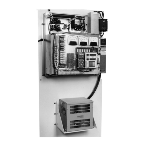
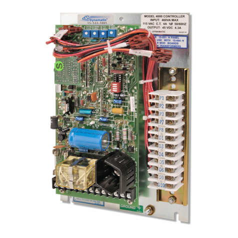
Dynamatic EC 2000-CES User manual

EC 2000 – CES
Stamping Press Position Controller
Instruction Manual
Sturtevant, Wisconsin, USA 53177
Telephone: 262-554-7977
Fax: 262-554-7041
Toll Free: 800-548-2169
www.dynamatic.com

EC-2000-CES MANUAL
2
Table of Contents
SECTION 1 - THEORY OF OPERATION ............................................................................................................... 6
SECTION 2 – MODELS AND PART NUMBERS .................................................................................................... 9
SECTION 3– SPECIFICATIONS ......................................................................................................................... 10
3.1 Features ..................................................................................................................................... 10
3.2 Power and Load Ratings ............................................................................................................. 10
3.3 Electrical Protection ................................................................................................................... 10
3.4 Environmental Ratings ............................................................................................................... 11
3.5 Electrical Noise ........................................................................................................................... 11
3.6 Enclosures .................................................................................................................................. 11
3.7 Weight ........................................................................................................................................ 11
3.8 Dimensions (see Figure 3&4) ..................................................................................................... 11
3.9 Reliability .................................................................................................................................... 11
3.10 Codes and Standards.................................................................................................................. 11
SECTION 4 – CONTROL OPERATION MODES.................................................................................................. 13
4.1 Control Modes ........................................................................................................................... 13
4.2 Mode of Operation ................................................................................................................... 13
SECTION 5 – Inputs/Outputs .......................................................................................................................... 14
5.1 Analog Inputs ............................................................................................................................. 14
5.2 Digital Inputs .............................................................................................................................. 14
5.3 Analog Outputs .......................................................................................................................... 14
5.4 Digital Outputs ........................................................................................................................... 14
SECTION 6 – INSTALLATION ........................................................................................................................... 15
6.1 Panel & Keypad Layouts ............................................................................................................. 15
6.2 Mounting Hardware ................................................................................................................... 18
6.3 Wiring ......................................................................................................................................... 18
6.4 Hardware Jumper & Potentiometer Setup ................................................................................ 19
SECTION 7 – KEYPAD ...................................................................................................................................... 22
SECTION 8 – PROGRAMMING ........................................................................................................................ 23
8.1 Menu A: Control Setup .............................................................................................................. 23
8.2 Menu B: CLCH PERFORMANCE .................................................................................................. 26
8.4 Menu C: ACCEL/DECEL SETUP ......................................................................................................... 27
8.4 Menu D: BRAKE PERFORMANCE ...................................................................................................... 27

EC-2000-CES MANUAL
3
8.5 Menu F: PROCESS ....................................................................................................................... 29
8.6 Menu G: FAULT .......................................................................................................................... 30
8.7 Menu H: FAULT TIMER SETUP .......................................................................................................... 31
8.8 Menu I POSITION ERROR SETUP .................................................................................................... 34
8.9 Menu J: METER SETUP ..................................................................................................................... 35
8.10 Menu K: SERIAL OPTIONS .............................................................................................................. 35
SECTION 9 – PRESS CONTROL OPERATION -- WIRED INTERFACE .................................................................. 36
9.1 CONTROL INPUT SIGNALS ................................................................................................................ 36
9.2 CONTROL - OUTPUT SIGNALS .......................................................................................................... 37
9.3 PRESS CONTROL INTERFACE - SERIAL PORT ..................................................................................... 38
9.4 SIGNALS FOR CUSTOMER’S RECORDER ........................................................................................... 39
9.5 BRAKE CONTACTOR.......................................................................................................................... 39
9.6 CONTROL OPERATING MODES ......................................................................................................... 39
SECTION 10 – STARTUP & ADJUSTMENT ....................................................................................................... 43
10.1 POWER CONVERSION .................................................................................................................... 43
10.2 PRESS SPEED CONTROL .................................................................................................................. 43
10.3 BRAKE CONTROL BOARD ................................................................................................................ 43
10.4 CLUTCH CONTROL BOARD ............................................................................................................. 44
10.5 PRE-START-UP PROCEDURE ........................................................................................................... 44
10.6 START-UP PROCEDURE................................................................................................................... 46
SECTION 11 – FAULT LISTING & DESCRIPTIONS ............................................................................................. 48
11.00 FAULT LIST .................................................................................................................................... 48
11.01 LEVEL 100 FAULTS ........................................................................................................................ 48
11.02 LEVEL 200 FAULTS ........................................................................................................................ 48
11.03 LEVEL 300 FAULTS ........................................................................................................................ 50
SECTION 12 PRESS CONTROL INTERFACE - SERIAL PORT ............................................................................. 52
12.0 SERIAL PORT PRESS CONTROL INSTRUCTIONS .............................................................................. 52
12.1 SERIAL PORT PARAMETER DATA PACKET INSTRUCTIONS ............................................................. 53
12.2 SERIAL PORT PARAMETER DATA PACKET INSTRUCTIONS (ALTERNATE METHOD)........................ 54
12.3 SERIAL PORT EXECUTE PARAMETER INSTRUCTION ....................................................................... 54
12.4 SERIAL PORT FAULT REPORT INSTRUCTION ................................................................................... 54
12.5 SERIAL PORT FAULT REPORT DATA PACKET CONTENT .................................................................. 55
12.6 SERIAL PORT MONITOR DATA INSTRUCTION ................................................................................ 55
EC-2000-CES MANUAL
4
12.7 SERIAL PORT MONITOR DATA PACKET CONTENT .......................................................................... 55
12.8 SERIAL PORT CONNECTIONS .......................................................................................................... 56
SECTION 13 – TROUBLESHOOTING ................................................................................................................ 57
13.1 TROUBLE SHOOTNG 100 LEVEL STOP MOTOR FAULTS ................................................................. 58
13.2 TROUBLE SHOOTNG 200 LEVEL STOP NOW FAULTS ..................................................................... 58
13.3 TROUBLE SHOOTNG 300 LEVEL STOP ON TOP FAULTS ................................................................. 62
13.4 TROUBLE SHOOTING. NO FAULT DISPLAYED: ................................................................................ 64
13.41 Blank Display: ............................................................................................................................... 64
13.42 Keypad Does Not Respond. Display works: ................................................................................. 65
13.43 Control does not engage. No faults: ............................................................................................ 65
13.44 Unit runs at top speed only - No control: .................................................................................... 65
13.45 The speed range is limited—doesn’t reach maximum speed: ..................................................... 65
13.46 High Voltages Fuses blow on power up: ...................................................................................... 66
13.47 High Voltages Fuses blow while running: .................................................................................... 66
13.48 Low Voltages Fuses on clutch control board blow: ..................................................................... 66
13.49 Low Voltages Fuses on brake control board blow: ...................................................................... 66
13.50 Unstable Speed Running: ............................................................................................................. 66
13.51 Unstable Speed Slowing or Braking: ............................................................................................ 67
Table of Figures
Figure 1: Eddy Current Drive Block Diagram ................................................................................ 7
Figure 2: EC 2000-CES Keypad Display...................................................................................... 8
Figure 3: Standard Panel Dimensions (Not to scale) ..................................................................... 15
Figure 4: Keypad Cutout Template (to Scale, Inches) .................................................................... 16
Figure 5: Keypad Dimensions (to Scale) .................................................................................... 17
Figure 6: Clutch Control Board Layout ....................................................................................... 20
Figure 7: Brake Control Board Layout ........................................................................................ 21
Figure 8: Keypad Layout ......................................................................................................... 22

EC-2000-CES MANUAL
5
Listing of Tables
Table 1: Models and Part Numbers ............................................................................................. 9
Table 2: Clutch Control Board Programmable Jumpers Default Settings in Green ................. 19
Table 3: Follower Set Point Jumper Settings .............................................................................. 19
Table 4: Brake Control Board Programmable Jumpers .................................................................. 21
Table 5: Keypad Button Descriptions ......................................................................................... 22
Table 6: Mechanical Unit Tach Pulses/REV Setting ...................................................................... 24
Table 7: Parameter Locations .................................................................................................. 40
Table 8: Press Run Data Format .............................................................................................. 53
Table 9: Control Fault Data Format ........................................................................................... 55
Table 10: Control Monitor Data Format ...................................................................................... 56

EC-2000-CES MANUAL
6
SECTION 1 - THEORY OF OPERATION
The Dynamatic® Eddy Current CES press drive system consists of a prime mover (AC induction motor), an
AC motor starter (optional and not provided), the Eddy Current coupling, Eddy Current Brake a speed
feedback device (tachometer generator), a resolver (position measurement) and a controller with an
operator interface.
The AC motor is started under no load and runs at full speed before the controller is energized The
output of the control is determined by reference setting (based on press position) and feedback
magnitude with drive speed and torque being based on the operational mode and load requirements.
Speed control mode with tachometer or resolver feedback will regulate within 0.5% of set speed. Preset
speeds, and external reference inputs are available as standard parameter selections with the EC 2000-CES
control.
The EC 2000-CES uses digital technology to provide a flexible, low noise control for today’s high tech
industrial environment. It provides setup and programming via a keypad with a user friendly
alphanumeric display; drive parameters may be programmed and displayed by the customer to activate
the many built-in features. Below is a schematic of a typical press drive.

EC-2000-CES MANUAL
7
Figure 1: Eddy Current Drive Block Diagram

EC-2000-CES MANUAL
8
Figure 2: EC 2000-CES Keypad Display

EC-2000-CES MANUAL
9
SECTION 2 – MODELS AND PART NUMBERS
Table 1: Models and Part Numbers
Dynamatic Part
Number
Output
Voltage
Maximum
Current
Required
Input Voltage (50/60
Hz)
Notes
015-000248-2002 300VDC * 135A 600V 1ph ** SCRs in F.W. bridge rectification
015-000248-2003 300VDC * 80A 600V 1ph ** SCRs in F.W. bridge rectification
015-000248-2004 300VDC * 32A 600V 1ph ** SCRs in F.W. bridge rectification
* (Field Forcing to 600V -- Transformer sold separately)
** (Input Voltage with step up Isolation Transformer)

EC-2000-CES MANUAL
10
SECTION 3– SPECIFICATIONS
3.1 Features
Direct Drop in Replacement for Dynamatic Digital CES Controls, Galco or Control
Techniques
Voltage ranges available from 45 – 300VDC
Up to 135 amps output (see Table 1 for model list)
Control Modes (3) Speed (AC tachometer generator or pulse pickup), torque (clutch
current) feedback. Position Control with Resolver Feedback. Tach-less Speed control
when Resolver is used.
Six selectable angles and speeds. Programmable Creep Angle, Creep Speed and Stop
Angle
Adjustable brake & clutch current output
Controllable via potentiometer, follower signal (0-10V, 4-20mA), or Programmed angles
and speeds
Digital, noise free operation
Fuse and MOV protected
Back-lit LCD with keypad user interface
Recorded and displayed faults
RS422 / 485 Com port. Remotely programmable speeds and angles.
Ethernet IP add-on to be available
3.2 Power and Load Ratings
Input voltage: 200, 230, 460, 575V AC
Output Currents:24 to 135 Amp (See Table #1)
Output: Voltage 300VDC Field Forcing to 750 VDC with Inversion
Solid State Relay Outputs (5) Normal Stop Stop on Top, Stop Now, Stop Motor, &
Control Fault
Load Regulation: -0.25% load change from 25% to full load
Line Regulation: +/- 1% of rated speed for +/-10% change in line voltage
Thermal Drift: +/- 0.05% of rated speed per °C
Linearity: +/- 2% of maximum rated speed
Minimum Regulated Speed: 25 RPM
Linear Acceleration/Deceleration Range: 1% - 199% of top speed/sec or Instantaneous.
3.3 Electrical Protection
Fuses: Class T, 600V, 125 A
Circuit Breaker 125 Amp 2P
Metal Oxide Varistor on Clutch & Brake Output
1800V/m 10kA
Metal Oxide Varistor on power board line input
o 240V, 6.5kA

EC-2000-CES MANUAL
11
3.4 Environmental Ratings
Operating temperature range: 0°C to 40°C (enclosed or panel mount)
Storage temperature: -10°C to 75°C maximum
Humidity: 95% non-condensing
Elevation: to 1500 meters without derating
3.5 Electrical Noise
The control is immune to showering arc noise as specified by NEMA 519 test
procedures. Operation will not be affected by a 5 watt, 2-way radio transmission with
the enclosure door closed.
Noise Immunity and Radiation
The controller complies with FCC, part 15B, of federal regulation #47 as a Class A digital
device when operated in a defined enclosure and installed in accordance with our
instructions; third party verification is required.
EMI Susceptibility: Complies with IEC 801(1984)-3, class 2. It operates without fault or
disturbance under the specified level of radiated EMI (Performance Criteria 1).
3.6 Enclosures
Enclosures available upon request (lead times may vary)
Enclosures available with cooling and proper NEMA standards
3.7 Weight
3.8 Dimensions (see Figure 3&4)
Panel Mounted (Standard):
Keypad: 4.875"H x 4.875"W x 1.375"D
3.9 Reliability
Mean Time Between Failures: 50,000 hours
3.10 Codes and Standards
National Electrical Code (NEC) compliant

EC-2000-CES MANUAL
12

EC-2000-CES MANUAL
13
SECTION 4 – CONTROL OPERATION MODES
4.1 Control Modes
Speed (AC Tachometer Generator or Speed Pickup)
Torque (Current Feedback)
Position & Speed (Resolver Feedback)
4.2 Mode of Operation
Manual/Auto
o Allows the use to switch between an automatic signal (i.e. 4-20mA or 0-10V)
and the control potentiometer in Speed Mode
Start Stop – Utilizes Enable-High, Enable Low & Clutch Contactor
Six Preset Angles and Speeds
o Programmable through the keypad
Top Stop – Utilizes Creep angle Creep Speed & Stop Angle
Adjustable Braking
Ramp Control
Loss of Follower
User Process Units – Programmable SPM and Gear Ratio & Tach Pulses
Forward/Reverse Speed Control
ESTOP (TB2-31 and 32 are not closed)

EC-2000-CES MANUAL
14
SECTION 5 – Inputs/Outputs
5.1 Analog Inputs
Potentiometer/Reference Voltage
o Used for setpoints
5.2 Digital Inputs
Clutch On
Enable High
Enable Low
Inch High
Inch Low
Reverse
Continuous Mode
Fault Reset
5.3 Analog Outputs
Tach Pulses
5.4 Digital Outputs
Clutch Contactor On Relay NO
o 2A, 115VAC
Solid State Relays 120VAC
o Normal Stop
o Stop on Top
o Stop Now
o Stop Motor
o Control Fault

EC-2000-CES MANUAL
15
SECTION 6 – INSTALLATION
6.1 Panel & Keypad Layouts
Figure 3: Standard Panel Dimensions (Not to scale)

EC-2000-CES MANUAL
16
Figure 4: Keypad Cutout Template (to Scale, Inches)

EC-2000-CES MANUAL
17
Figure 5: Keypad Dimensions (to Scale)

EC-2000-CES MANUAL
18
6.2 Mounting Hardware
Standard Panel
o ¼” - 20 Bolts, Flat Washers, Lock Washers (Not included)
Keypad
o Included
6.3 Wiring
Dynamatic recommends adhering to the National Fire Protection Association’s “NFPA
70: National Electrical Code” codes and standards for proper branch protection, SCCR
ratings, and ampacity ratings.
o https://www.nfpa.org/codes-and-standards/all-codes-and-standards/list-of-
codes-and-standards/detail?code=70
Terminal Block Tightening Torque
o “TB” : 25 lb-in.
o “TB1” : 8.8 lb-in.
o “TB2” : 6 lb-in.

EC-2000-CES MANUAL
19
6.4 Hardware Jumper & Potentiometer Setup
a. Jumpers and Potentiometers on Clutch Driver Board 015-001201-0012
Table 2: Clutch Control Board Programmable Jumpers Default Settings in Green
Notes: **Remove Jumper J5 for 135 Amp Clutch Rating
**Remove Jumper J6 for 67 Amp Brake Rating
* Jumpers J7, J8, J15, J16 must all be in “A” or “B” Position
Table 3: Follower Set Point Jumper Settings
(**Set Point For CES Control)
Wire Jumpers W1 & W2 connect internal SCR’s. Cut for H.P. & CES controls
W3 connects fly back diode disabling Inversion. Cut if inversion is required.
Potentiometers:
R4 -- Measure TP1(-) to TP4(+) -- Adjust R4 for 5Volts +- .1
R29 -- SCR Pulse Position
R100 --Torque Limit – Not Used on CES Controller
Clutch Control Board Layout
JUMPER
PARAMETER
POSITION “A”
POSITION “B”
J2 Follower Operation
(Not Used on CES Control)
Pulse Pickup
(TB2-17)
Tach. Generator
(TB2-18 & 19)
J3 Process Feedback
(Not Used on CES Control) 0 TO 20VDC 0 TO 5, 10V
J4 Speed Control Feedback From Resolver
(TB2-2)
Tach. Generator
(TB1, G1 & G2)
J5 Clutch Current Feedback Scaling** 72 AMP (or less) Output 100 Amp Output
J6 Brake Current Feedback Scaling** 36 AMP (or less) Output 50 Amp Output
J7* Gating Pulse Train Standard and High
Power Controls
CES Press Drive
Control Only
J8* Sync Bias Standard and High
Power Controls
CES Press Drive
Control Only
J11 Clutch Gating Circuit Standard Control
On Board Pulse Xfmr
CES & High Power Control
Off Board Pulse Xfmr
J13 Clutch Current Feedback Circuit Standard Control
On-Board LEM’s
CES & High Power Control
Off-Board LEM’s
J14 Brake Current Feedback Circuit Standard Control
On-Board LEM’s
CES & High Power Control
Off-Board LEM’s
J15* Sync Bandwidth Standard and High
Power Controls
CES Press Drive
Control Only
J16* Sync Bandwidth Standard and High
Power Controls
CES Press Drive
Control Only
SIGNAL JUMPER
J9 J10
0 –10 VDC** A A
0 -5 VDC A B
4 – 20 MADC B B
8 – 40 MADC B A

EC-2000-CES MANUAL
20
Figure 6: Clutch Control Board Layout
Location of Jumpers on the Clutch power Board
Note that Jumpers J3 and J6 are located under the logic circuit board, if it is installed.
This manual suits for next models
3
Table of contents
Other Dynamatic Controllers manuals

Dynamatic
Dynamatic 4050 User manual

Dynamatic
Dynamatic 4000 User manual

Dynamatic
Dynamatic EC 2000 User manual

Dynamatic
Dynamatic CES User manual

Dynamatic
Dynamatic 4050 User manual

Dynamatic
Dynamatic 4050 User manual

Dynamatic
Dynamatic 4000 User manual

Dynamatic
Dynamatic 4000 User manual

Dynamatic
Dynamatic 4000 User manual