2CA600 O600EN1
Safety instructions – Personal safety
Special caution – Machine or component damage
The safety manual, which accompanies each
machine, must be studied by each operator of
the roller. Always follow the safety rules and
do not remove the manual from the roller.
This manual contains instructions concerning operation
and use of the roller. For information regarding care and
maintenance, see the manual, “MAINTENANCE, CA600".
When starting up and driving a cold machine,
which implies cold hydraulic fluid, the braking
distance will be longer than normal until the
machine reaches normal working temperature.
CONTENTS
WARNING SYMBOLS
SAFETY MANUAL
GENERAL CALIFORNIA
Proposition 65 Warning
Diesel engine exhaust and some of its
constituents are known to the State of
California to cause cancer, birth defects,
and other reproductive harm.
Page
Safety instructions (Read the Safety Manual also) .......... 3
Safety when driving .......................................................... 4
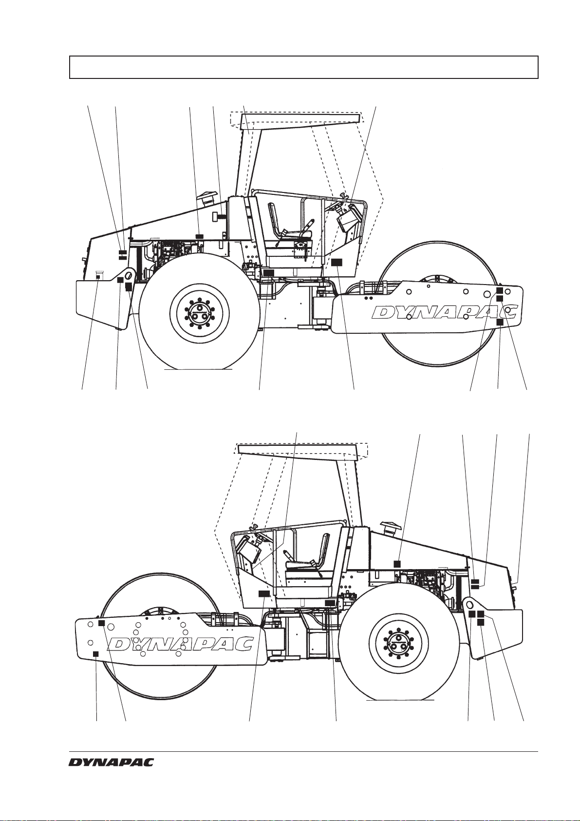
Safety decals, location/description ............................... 5, 6
Machine and engine plates ........................................... 7, 8
Instruments and controls .................................................. 9
Instruments and controls, functional description ...... 10, 11
Controls in the cab ......................................................... 12
Controls in the cab, functional description...................... 13
Before starting ...........................................................14-16
Starting ........................................................................... 17
Driving ............................................................................ 18
Vibration/Driving ............................................................. 19
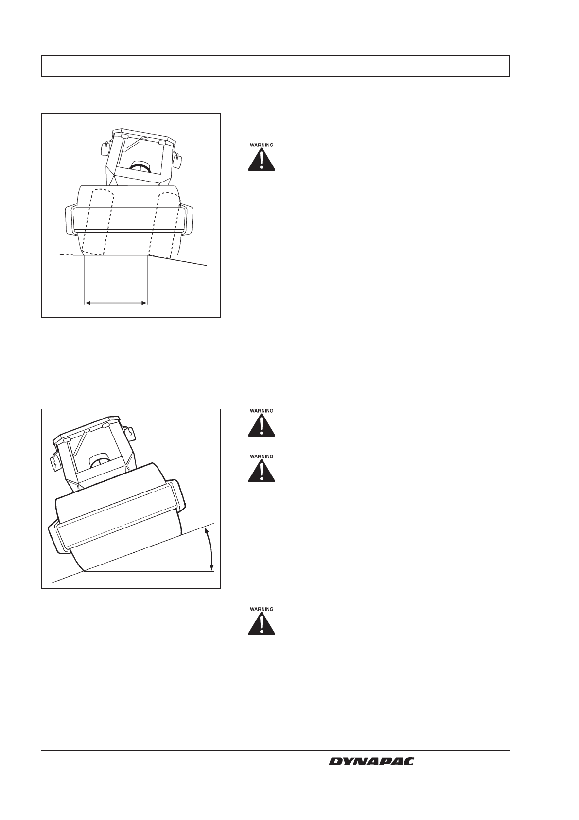
Driving on difficult courses ............................................. 19
Braking ........................................................................... 20
Parking ........................................................................... 21
Instructions for lifting ...................................................... 22
Towing ............................................................................ 23
Instructions for towing .................................................... 24
Transport ........................................................................ 25
Towing/Retrieval ............................................................ 25
Operating instructions - Summary ................................. 26