INSTRUCTIONS: IN-6000 Cod: DYN 27.04
Date: 20/10/2020 Revision: 04
4
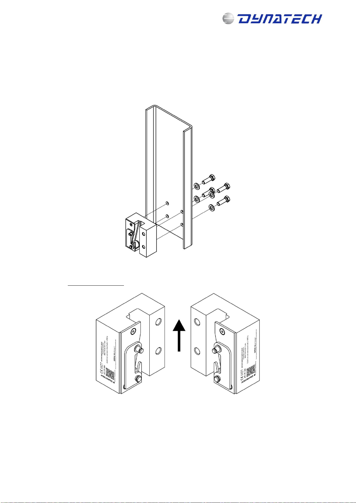
Figure 4: Improper assembly
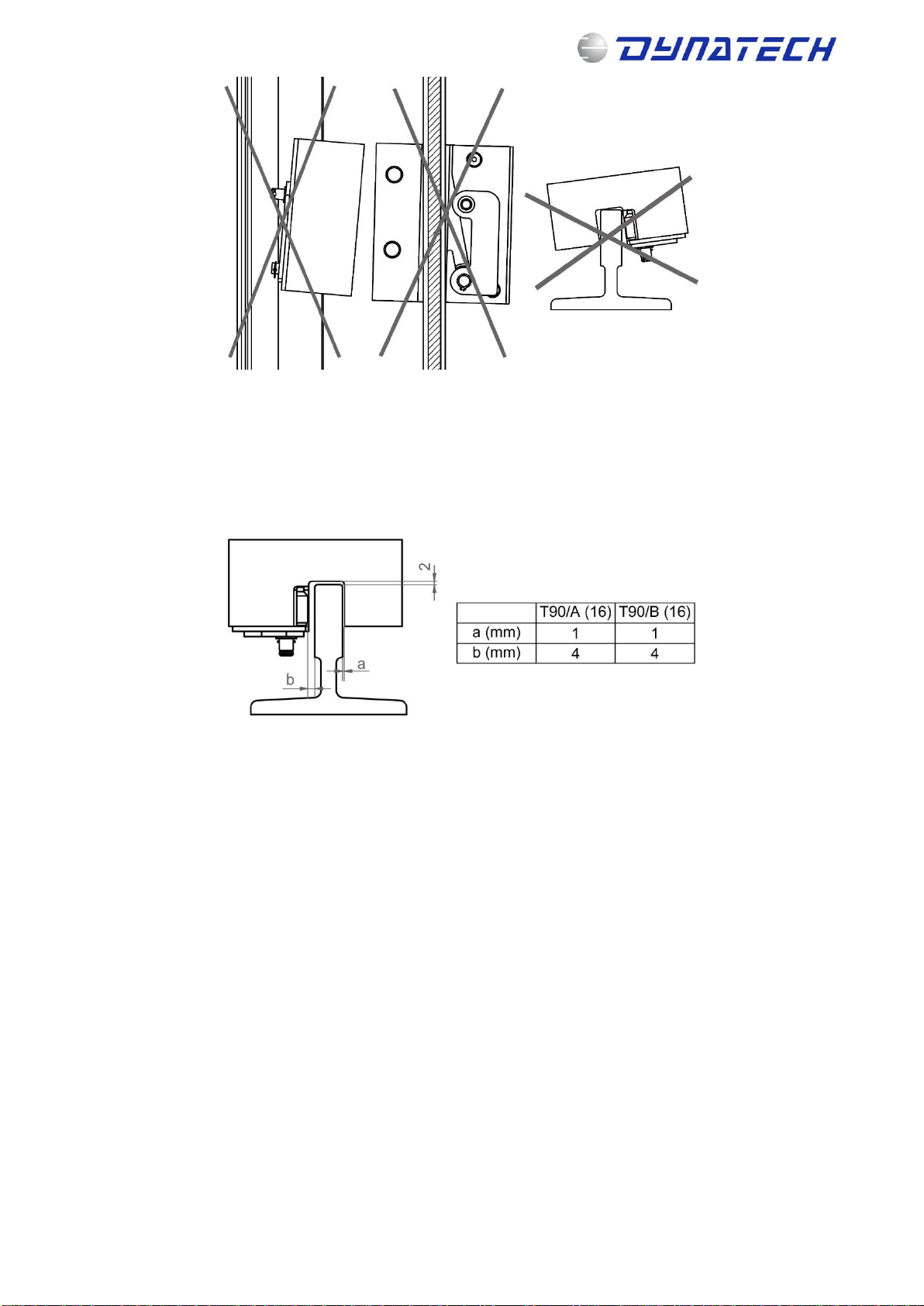
3.2 SAFETY GEAR ADJUSTMENT
⚠In order to avoid problems with the installation’s normal operation, it is very important that the person
carrying out the installation rigorously observes the distances mentioned in this item.
The guide rail's position in the block should be adjusted as follows. (see drawing DYN 27.C02.00).
Figure 5: Safety gear adjustment in relation to the guide rail
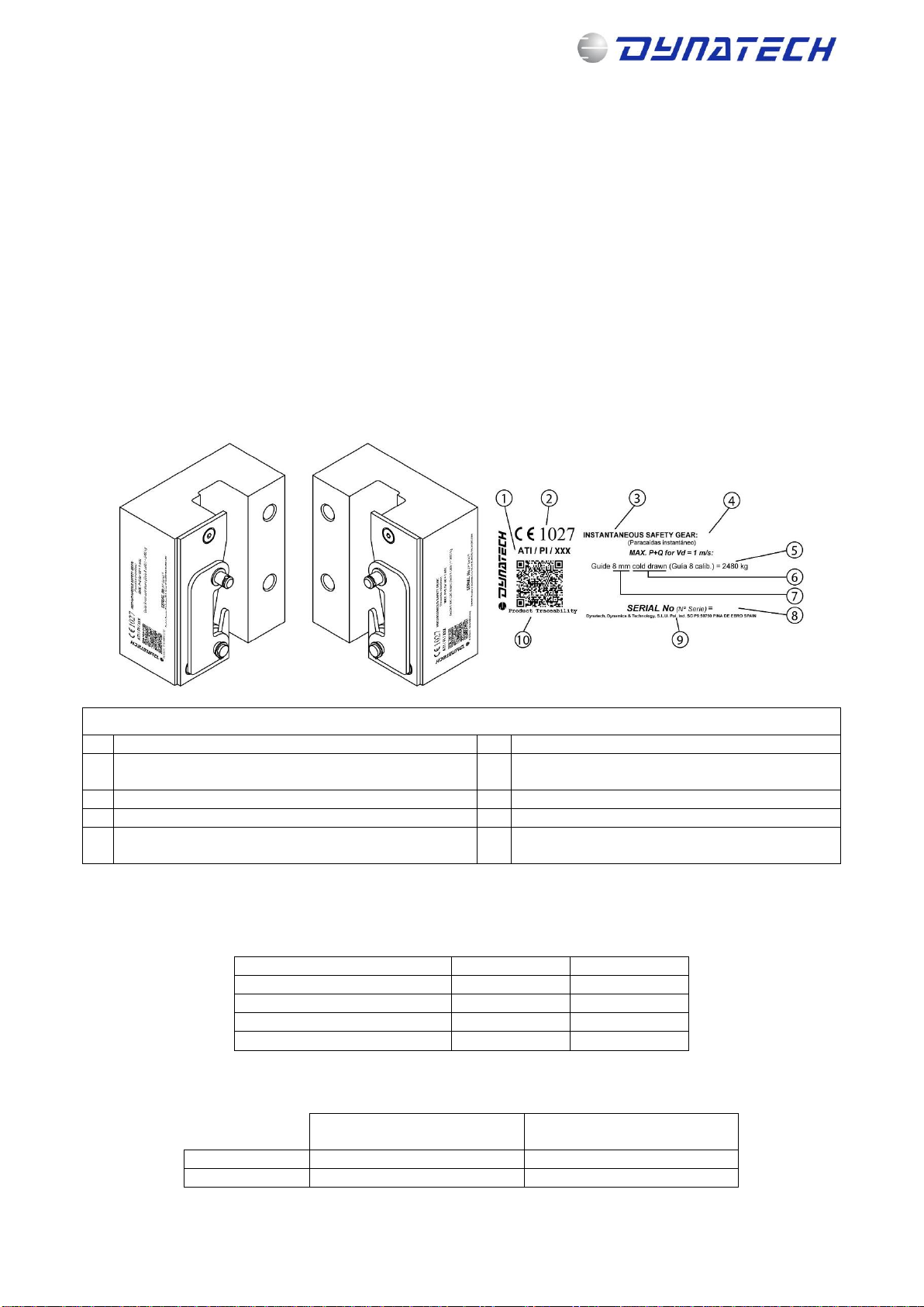
3.3 COUPLING THE DRIVING BAR
It is the responsibility of the person who installs the safety gear to properly position the driving bar in relation
to the safety gear, as well as to properly synchronise the safety gears controlled by that driving bar. The correct
position is when the safety gear roller is on the bottom of the block.
Once it has been fitted, and the safety gear’s rollers have been attached to the driving bar’s tripping bars, it
should be checked that both rollers operate simultaneously, controlled by the driving bar.
The minimum force required for tripping the safety gear is 300N.
⚠The Standard demands that the installation incorporate an AC-15 or DC-13 safety contact as defined in
EN 60947-5-1.
3.3.1 USING DYNATECH’S T-1 DRIVING BAR
Both safety gears may be synchronised by assembling Dynatech’s T-1 driving bar. For more information
concerning T-1 driving bar assembly, please consult its manual: DYN04 –Instructions T-1.
⚠It is not recommended to exceed a maximum force of 1900 N is not recommended with the governor.
Note: This manual displays partial information on the instructions for use and maintenance of this product. Please refer to the
customer area in Dynatech’s website in order to consult the full manual; http://customers.dynatech-elevation.com/