EN
ENGLISH
8
• Data transmission varies slightly based on the
protocol you're using; nevertheless, once you
start pedaling, the hometrainer starts and
continues sending data.
• Once pedaling has stopped for more than 2
minutes, the sensor enters standby mode (low
energy consumption mode) and the unit stops
transmitting data; to exit standby mode, simply
start pedaling again and the sensor will
beginsending data. This is the reason that it is
necessary to start pedaling before connecting to
the app or to other devices.
NOTE: A device must be compatible with the
"ANT+ Speed and Cadence" protocol to display
speed and / or cadence data on an ANT™+ cycle
computer or GPS device. A device must be
compatible with the "ANT™+ Power" protocol to
display power data on an ANT™+ cycle computer
or GPS device.
A list of devices compatible with one or more of
these protocols is available at the ANT™+
website:
http://www.thisisant.com/directory
Please check the ELITE website and its related
FAQ for more info.
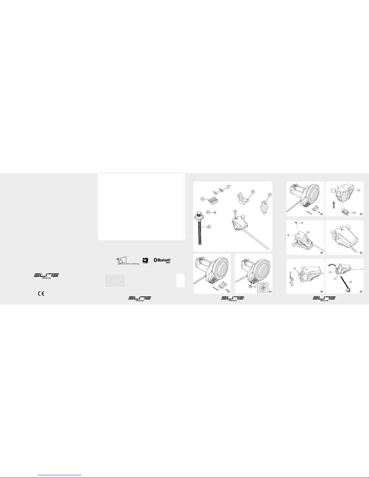
CALIBRATING THE SHIFT LEVER
Please follow these steps if you notice incorrect
power data while training; the cause may be an
incorrect sync between power data and selector
position. We suggest proceeding with the
following calibration on the motherboard:
•
Open the battery compartment (Pic.1)
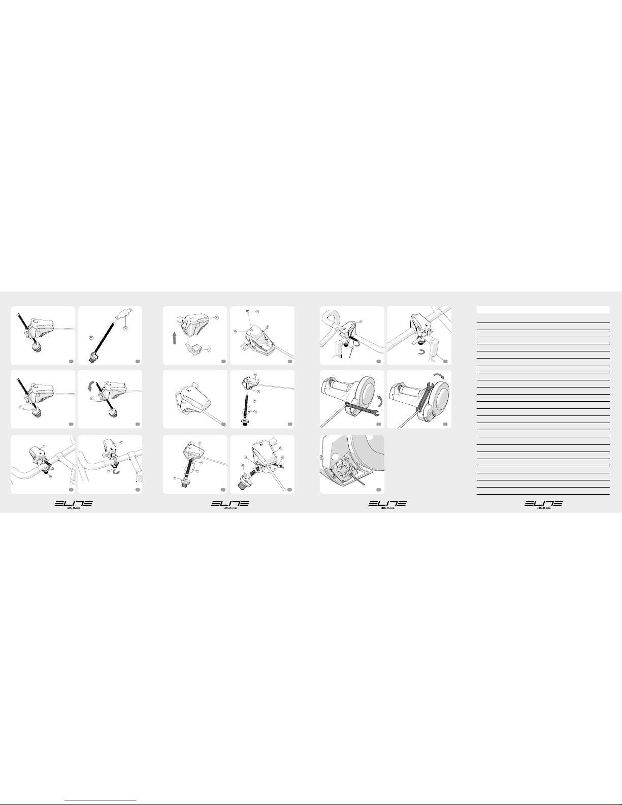
•
Move the lever to its min position (lvl 1);
•
Press and hold the button on the motherboard
for five (5) seconds (Pic. 25) until it blinks three (3)
times;
•
Start pedaling, once above 10Km/h increase the
level every 5 seconds until you attain to the max
available resistance (8);
•
Continue pedaling at the max available
resistance (8) for 5 more seconds.
NOTE: Do not shift gears while pedalling.
NOTE: It is possible to decrease speed below the
minimum resistance level (1).
•
If the procedure was successful, the LED light
will remain on for 20 seconds; otherwise, after
120 seconds (the max time allowed for calibrating)
the LED light will blink for 20 seconds.
•
Close the battery compartment (Pic. 3).
BICYCLE REMOVAL
•
Remove the remote regulation shifter from the
handlebar.
WARNING
• The smartphone / tablet / cycle computer must
be compatible with ANT™+"Speed and
Cadence", ( ), “ANT™+ Power” ( ) or
Bluetooth Smart ( ) protocols.
• Even though the resistance unit can connect to
an external device, automatic adjustment of
resistance levels by the app / cycle computer is
not possible. The cyclist will have to manually
adjust resistance with the selector.
• During use of the Power Mag Smart B+ with
Elastogel roller, slight wear of the roller is quite
normal. Tests carried out at Elite show that after
continuous use for 20,000 km, roller wear is
around 0.1 mm, and since the total thickness is
10 mm, correct operation of the trainer will not be
affected even with far greater wear. Claims that
are due to improper or careless use, will not be
acknowledged. Slight wear of the part in rubber is
quite normal.
• Using the Power Mag Smart B+ with narrow
tyres or with unsuitable tyre pressures can
permanently damage the Elastogel roller.
• Do not store the Power Mag Smart B+ in wet or
damp places. The electronic components could