E-matic PMCSF6 User manual
cLens dMain Body
ePower Cord
INTRODUCTION
The use of occupancy detectors in commercial and industrial applications can
significantly reduce energy usage lessening both energy costs and helping the
environment.
The PMCSF6 360 degrees MICRO SENSITIVE flush mount OCCUPANCY
DETECTOR uses passive infrared sensors (PIR) which react to changes in
temperature emitted by the slight motion of persons or objects passing through its
detection area. The PIR sensor automatically operates the connected load when
an area is occupied. After a preset time on non-activation (when an area is
vacated) the load will be switched off. In addition the built in photocell takes
natural light (daylight) into account when determining its activation.
Note: Read this entire manual before you start to install the system.
SAFETY PRECAUTIONS
zDo not install when it may be possible for water to access the fitting.
zBe sure to switch off power source before installing.
zMake sure that the mains wiring comes from circuit with an external miniature
circuit breaker not higher than 10A for the short circuit protection or a suitable
fuse.
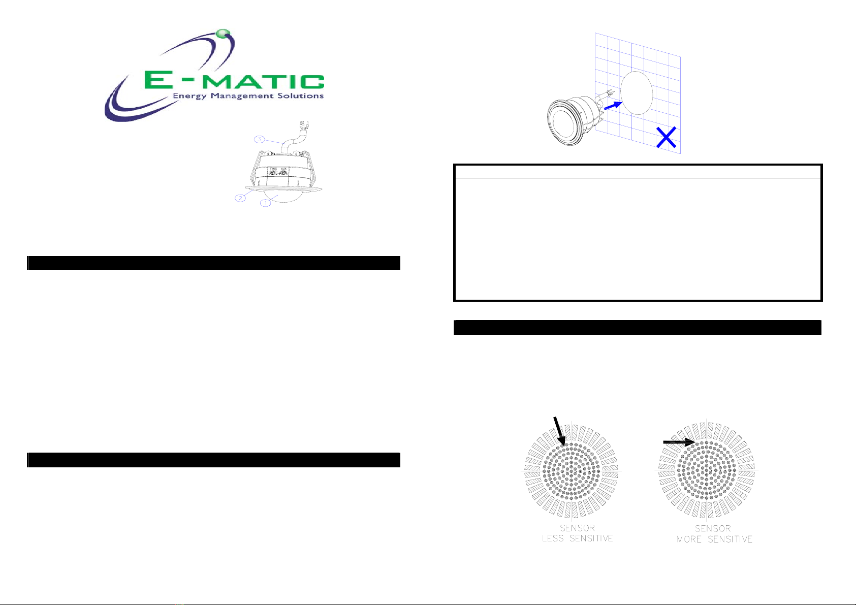
zThe unit should not be installed on the wall. (FIGURE 1)
FIGURE 1
IMPORTANT
Installation must be performed by a skilled/competent person who is familiar
with the appropriate standards and technical requirements of the appliance and
its proper installation.
Before proceeding with the installation, TURN OFF THE POWER TO THE
LIGHTING CIRCUIT AT THE CIRCUIT BREAKER OR FUSE BOX TO AVOID
ELECTRICAL SHOCK.
CHOOSING A MOUNTING LOCATION
zAvoid aiming the motion sensor at heating vents, air conditioners or objects
which may change temperature rapidly.
zDo not allow sunlight to fall directly on the front of unit.
zThe motion sensor is more sensitive to objects moving across its field of view.
It is less sensitive to an object moving directly towards the sensor head.
(FIGURE 2)
FIGURE 2
PMCSF6
OCCUPANCY SENSOR

INSTALLATION
The unit has a sensing angle of 360°. It detects micro movement within a 6m
diameter (sitting zone) and can detect general movement up to 10m diameter at a
mounting height of 2.5 meters. (FIGURE 3)
FIGURE3
SCHEMATIC
FIGURE 4
WIRING INSTRUCTION
(1) Switch off the power source or wall switch.
(2) Strip approximately 6-8mm insulating part of the wires from the terminal
block.
(3) The connection of all power cable is via a junction box. (Not supplied). The
power cable of “LS” and “N” is to be connected to LS and N of the light fitting.
(FIGURE 5)
FIGURE5
(4) In order to install the sensor to the ceiling, drill a diameter of 65mm round
hole on the ceiling. Wedge the main body into the round hole directly.
(FIGURE 6)
FIGURE6
IMPORTANT: DO NOT PULL THE SPRINGS AWAY FROM THE BODY, THIS
WILL DAMAGE THE SPRING TENSION AND RENDER THE
WARRANTY INVALID.
OPTIONAL
65
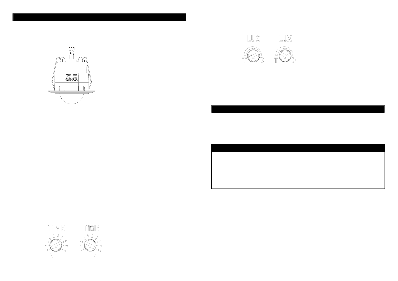
SETTING THE LIGHTING SYSTEM
(1) TEST MODE
Turn the Lux control and the Time control counter-clockwise to the edge - the
TEST position. (FIGURE 7)
FIGURE7
Turn the power supply switch on, the light will turn on immediately and wait
for about 1 minute to warm up the unit. After warm-up time is expired and
the light goes off, you may do a walk test and the light will turn on. This
confirms that the wiring is correct and that the light is working.
Walk through the coverage area. The light will turn on for about 5 seconds
when motion is detected and turn off shortly after motion stops. Wait for the
light to turn off before moving again to test the sensor.
(2) SETTINGS
TIME ADJUSTMENT
The TIME adjustment controls how long the light will stay on after motion has
been detected.
Adjust the TIME Control Knob clockwise to increase the turn-off time (40 minutes
maximum) or counter-clockwise to decrease the turn-off time (5 seconds
minimum). (FIGURE 8) There are ten selections for time adjustment (from MIN
to MAX) -- 5, 10, 20, 40, 80, 160 second and 5, 10, 20, 40 minute.
FIGURE8
LUX ADJUSTMENT
The LUX adjustment determines at what light level the light will start operating
when you set the sensor to the AUTO MODE.
FIGURE9
Provisionally turn the LUX Control Knob to the edge clockwise at the moon (dusk)
position. (FIGURE 9) In this provisional setting mode, the Motion Sensor remains
inactive during daylight. At dusk when you find it is the LUX level you desired for
operation, simply set the LUX control knob to the position that you tried
satisfactorily.
OPERATION
Automatic Operation
When the sensor detects motion, the light automatically turns on. The built-in
photocell turns the sensor off and on according to the light level selected by the
LUX adjustment.
TROUBLESHOOTING
Light does not turn on
zConfirm that you have mains at the fitting and connections are correct.
zMake sure that the bulbs have not burned out.
Light remains on
zMake sure the wiring connection is correct.
zCheck if the TIME /LUX settings are correct.
About 5sec About 40min

SPECIFICATIONS
Power Requirement AC 230V / 50Hz
Lighting Load
Max. Incandescent: 2000W
Max. Halogen: 2000W
Max. Fluorescent / Cos Ө=0.5: 1500W, For quantity of
fittings refer table
Max CFL/ PL/ LED :10 pieces
Detection Angle Up to 360°at 25°C at 2.5m height
Micro movement:
Up to 3m radius at 25°C at 2.5m height
Detection Distance General movement:
Up to 5m radius at 25°C at 2.5m
height
Mounting Height Recommended 2.2 ~ 3.0m Ceiling Mount
Wall Switch Control Auto/Off
Time Adjustment Approx. 5 seconds to 40 minutes (5, 10, 20, 40, 80, 160
second & 5, 10, 20, 40 minute)
Lux Adjustment Approx. 30 ~ 200 Lux & test mode
Warm Up Time About 1 min
Protection Class Class II
Protection Degree IP20 WHEN INSTALLED
Safety CE
Due to our policy of continuous improvement we reserve the right to change
specification without prior notice.
Errors and omissions excepted. These instructions have been carefully
checked prior to publication. However, no responsibility can be accepted
by E-Matic for any misinterpretation of these instructions.
Warning:
Do not dispose of electrical appliances as unsorted municipal waste, use separate
collection facilities.
Contact your local government for information regarding the collection systems
available.
If electrical appliances are disposed of in landfills or dumps, hazardous
substances can leak into the groundwater and get into the food chain, damaging
your health and well-being.
E-Matic Energy Management Solutions,
4 Arkwright Court, Fylde Industrial Estate,
Blackpool, Lancashire, FY4 5DR.
Tel: 01253 791888, Fax: 01253 791887,
Web site: www.e-matic.co.uk
A501111791R01
Rev03

Model PMCSF6
Lighting Maximum Load For
Incandescent (CosΘ=1)
2000W/8A(@240VAC)
Lighting Maximum Load For
Halogen (CosΘ=1)
2000W/8A(@240VAC)
Lighting Maximum Load For
Fluorescent T8 (CosΘ=0.5) 1500W/12A(@240VAC)
Lighting Maximum Load For
Fluorescent T5 (CosΘ≧0.9) 1500W/6.9A(@240VAC)
Lighting Load (number of fittings) for
Fluorescent T5
Conditions : Maximum quantity of ballasts and lamps listed
below;
Ballast Q'ty x (Lamp Q'ty x Watt)
22x(4x14W);
20x(2x21W);
20x(2x24W);
15x(2x28W);
15x(2x35W);
12x(2x39W);
12x(2x49W);
10x(2x54W);
10x(1x80W);
Lighting Load (Number of fittings) for
CFL & PL (Setup Conditions)
Conditions : Maximum quantity of lamps listed below;
Lamp Q'ty x Watt
10x9W
10x11W or 10x13W or 10x19W ;
10x20W or 10x23W ;
10x24W or 10x26W or 10x27W ;
10x32W or 10x36W or 10x38W ;
10x42W or 10x50W or 10x55W ;
10x80W:
Lighting Load For 10 Qty parallel connection
LED 200W total (Max.)
A501111791R01
Rev03
Table of contents
Other E-matic Accessories manuals


