e-motion add-e NEXT User manual

Page 1
add-eNEXT User Manual
EN
Vers. 3.6
e-motion your bike
with add-e

Page 2
Table of ConTenTs: User ManUal
Table of conTenTs: User ManUal p. 2
foreword & iMporTanT inforMaTion p. 3
legal inforMaTion p. 4
safeTy insTrUcTions p. 5
warranTy/disclaiMer p. 6
explanaTion of syMbols p. 7
scope of delivery p. 8
add-enexTinsTallaTion ManUal p. 9
Table of contents: Installation Manual p. 10
Section 1: Determining which variant is right for you p. 11
Section 2: Assembling the kit p. 14
Section 3: Drive unit & mechanical setting p. 25
Section 4: Special notes to the installation process p. 31
add-enexToperaTing ManUal p. 33
Table of contents: Operating Manual p. 34
1. add-e NEXT drive unit p. 36
2. add-e NEXT battery p. 41
3. add-e NEXT chargers & docking station p. 50
4. add-e NEXT sensors p. 53
5. add-e NEXT remote control p. 58
6. add-e NEXT sport mapping p. 62
7. add-e NEXT smartphone app p. 63
8. add-e NEXT software update p. 64
9. Tipps & tricks for troubleshooting p. 79

Page 3
foreword & iMporTanT inforMaTion
Thank you for purchasing your add-e NEXT retrofit kit. This manual contains instal-
lation information.
Before you start, it is important that you familiarise yourself with the various instal-
lation variants.
This manual should be kept in a safe place by the customer and given to the new
owner if the conversion kit is eventually passed on.
Our add-e NEXT auxiliary drive unit is designed to be easily retrofitted to almost
any bike. You do not need any particular prior knowledge for this. Nevertheless,
we do recommend that you only carry out the initial installation yourself if you
have already had some experience doing manual work on a bike. If you encounter
difficulties or deviations from this user manual, our partners are at your disposal to
help you. Use the store locator on our website at www.add-e.at/haendlersuche. You
can also find more information, pictures and videos through our homepage at
www.add-e.at.
All directions given in this manual refer to the normal direction of travel. The chain
ring is on the right-hand side in the direction of travel and the saddle is located
above the bottom bracket.
The add-e NEXT retrofit kit can be used on a wide range of bike types (MTB, racing
bike, trekking bike, city bike, etc.). However, we cannot rule out the possibility that
highly different frame shapes and/or additional equipment may make it impossib-
le to install the add-e NEXT retrofit kit. In particular, pressed-in bottom brackets
(Pressfit) and full-suspension bikes (Fullys) may make it impossible to use the instal-
lation kit. Further information on this subject can be found on our website at
www.add-e.at/faq.
In some cases, you may need special tools to work to a professional standard.
These make the work a lot easier, do not cost much and can be ordered from our
online shop at www.add-e.at/shop.
Although the graphics and text in this user manual have been produced with the
greatest care, we cannot accept liability for any errors, inconsistencies and the
consequences thereof.
We update this manual continuously. You can download the latest version from our
website at www.add-e.at/montage.

Page 4
legal inforMaTion
According to pedelec standard EN 15194/2017, the max. assistance speed is 25
km/h with a nominal continuous power of 250W. The add-e NEXT Sport is equip-
ped with mapping 2. This means that it has a max. assistance speed of 25 km/h
and a max. power of 600W. This corresponds to the above standard, because the
600W indicates the peak power.
The add-e NEXT Sport Edition allows travel at an average higher speed (max. up to
45 km/h). In order to use the add-e NEXT Sport in the European Union in com-
pliance with the law, it is factory delivered with mapping 2 (25 km/h, 600W peak
power). These parameters can only be modified if a dongle is fitted to the drive
unit. If you disconnect this dongle after modification, no risk of tampering exists,
even if there is an accident, and the set maximum speed (25 km/h) also applies to
add-e NEXT Sport as the maximum design speed in accordance with the registrati-
on-free pedelec standard EN 15194/2017.
The parameters can be changed by the user at own request with the dongle, both
for the motor power and for the maximum speed, but this no longer complies with
the EN 15194/2017 standard.
If the configuration chosen does not comply with the applicable legal regulations
in the country of use, the add-e NEXT is only allowed to be used with a special
license and/or for racing purposes and/or on private property.
Different countries have different regulations for the use of e-drive units on bikes.
Generally, the overall bike is used for assessment. Whether other regulations also
apply when an e-motor is retrofitted, e.g. for lighting, depends on the country in
question and compliance is the responsibility of the user.
The user is responsible to inform himself about the legal regulations that apply in each
case and for complying with them accordingly. Off-road restrictions regarding electrical
power, maximum speed and pedal assistance also need to be complied with.

Page 5
safeTy insTrUCTions
Before putting the unit into operation, the user should read through the complete
manual, since it provides important information about correct operation and mini-
mises the risks. If damage does occur due to failure to observe these instructions,
the manufacturer accepts no liability, and the guarantee/warranty is void.
Proper functioning of the bike and the add-e NEXT retrofit kit is essential and
reduces the risk of injury or accidents with potentially fatal consequences for the
cyclist and others.
For your own safety, please ensure that you wear the proper protective clothing
and a helmet. First, practice with care on a suitable track to get used to the new
handling behaviour with the add-e.
Depending on the frequency of use, you should inspect and may need to clean the
add-e NEXT retrofit kit and its parts on a regular basis.
Before each journey, check the bike for the correct motor setting, tyre pressure/
condition and the secure fit of the add-e, and adjust if necessary!
Ensure that no moving parts, e.g. cables of the drive unit or other objects, can get
caught between the drive unit and the tyre, otherwise unexpected problems may
ensue, including the rear wheel jamming.
The motor swing arm must always remain mobile, do not let objects get wedged
in it. Otherwise, this may result in the motor no longer disengaging from the rear
wheel and/or unwanted damage.
The motor of the drive unit can get very hot while travelling. Avoid touching it
directly after use, as this could lead to burns and injuries.

Page 6
In the area covered by EU law, the vendor is liable for material defects for at least
the first two years after the date of purchase. For battery cells, this is limited to 6
months from the date of purchase.
This covers defects that already existed at the time of delivery. In the first six
months, it is assumed that the defect already existed at the time of purchase. A
requirement for the purchaser to make a claim is that all specified conditions were
complied with during installation, use and maintenance.
These regulations only apply to states that are subject to EU law. In Switzerland and
other non-EU countries, liability is limited to one year after the date of purchase.
Wearing parts, such as the battery casing (scratches, falls, impact, etc.), friction
roller, scratches and damage attributable to the user's personal negligence are
excluded from the warranty.
Any form of manipulation or modification not expressly permitted in the installa-
tion or operating manual, assembly video or by written permission from GP Motion
GmbH invalidates the warranty .
Damage to the add-e NEXT battery caused by a complete discharge (e.g. due to
prolonged lack of use) or by using a different charger is excluded from the warran-
ty. If the add-e NEXT battery is not used for a longer period of time, it should be
removed from the battery holder.
In the case of a warranty claim, please contact the respective retailer. The ma-
nufacturer or specialist retailer will repair or replace the defective parts. For the
purpose of processing the warranty claim, the customer is required to send in the
defective parts or the add-e NEXT kit.
The "Repair Order" form is available online at www.add-e.at/montage or from
[email protected]. This form needs to be filled in carefully and enclosed with the
delivery. Warranty claims without a correctly completed form may result in higher
costs and a delay in the repair. The customer is responsible for ensuring that the
parts sent in are suitably wrapped to avoid damage in transit. The manufacturer ist
not liable for damage that occurs during transport.
Removing the serial number from the add-e NEXT battery or the add-e NEXT drive
unit voids the warranty.
Spare parts are available from the retailer.
Failure to observe the information provided in this manual, improper use or use for
purposes other than those the product is intended will result in GP Motion GmbH
rejecting the claim for damage to and caused by the product. Liability for conse-
quential damage to elements of any kind or persons is excluded.
The manufacturer accepts no responsibility for and will not refund any costs incur-
red as a result of improper use.
warranTy/disClaiMer
Page 7
explanaTion of syMbols
PLEASE NOTE!
This symbol stands for special instrucons which need to be follo-
wed during use or installaon.
TIP!
This symbol stands for special ps that make use or installaon
easier.
ATTENTION!
This symbol stands for IMPORTANT informaon and instrucons
for assembly or use. It is imperave that you observe these in order
to avoid hazards.
This marking means that the parts are not allowed to be disposed
of in household waste
CLEANLINESS!
Secons marked with this symbol indicate that special aenon
needs to be paid to cleanliness here.
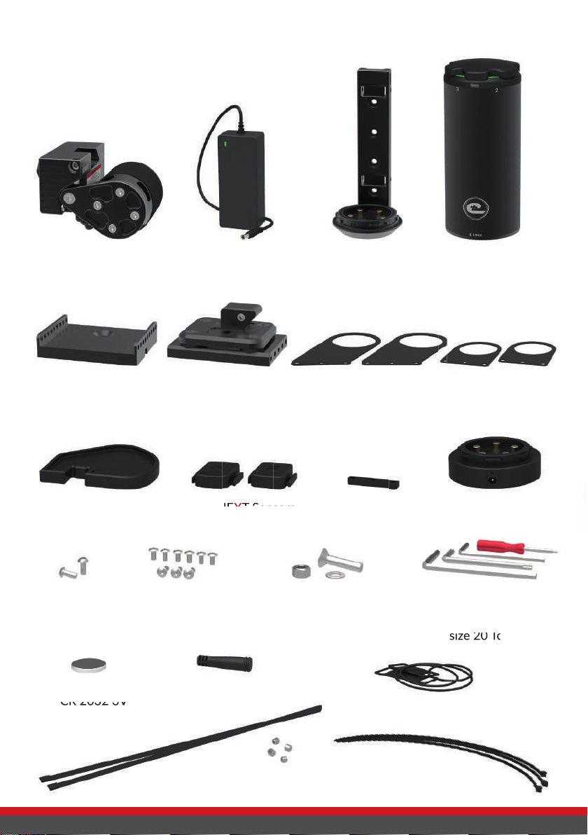
Page 8
add-e NEXT battery
add-e NEXT drive unit add-e NEXT charger
add-e NEXT Sensors
Assembly arms
short
Stand plate Damper plate Assembly arms
long
Setting gauge
Battery holder
6x M4 Torx screws
3x M4 Torx screws
long
Spacer
Dongle
size 3 Allen key
size 4 Allen key
size 6 Torx key
size 20 Torx key
Cable ties
long
Button cell
CR 2032 3V
sCope of deliVery
Docking station
size 20 Torx key
O-rings & rubbers
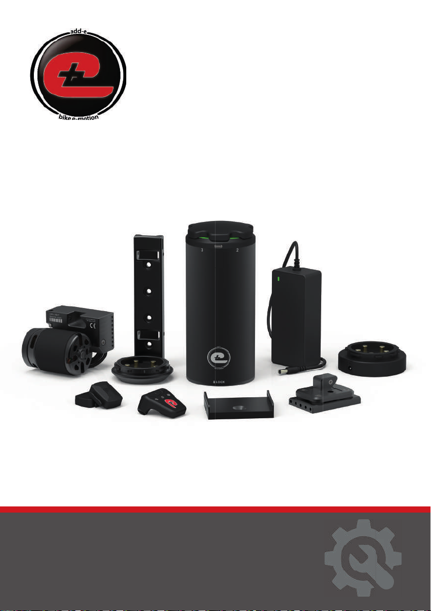
add-e NE
add-e NE
X
X
T Sensors
T Sensors
CR 2032 3V
2x Steel straps
4x M6 grub screws
2x M5 Allen
screws
1x 8mm Washer
1x M8 Nut
1x M8 Screw
Page 9
add-eNEXT Instalation Manual
EN
Vers. 3.6
e-motion your bike
with add-e

Page 10
Table of ConTenTs: insTallaTion ManUal
secTion 1: idenTificaTion of insTallaTion varianT p. 11
Variant 1: Installation at the side stand p. 12
Variant 2: Installation at the bottom bracket p. 13
Variant 3: Installation with the Hebie counterplate p. 13
secTion 2: asseMbling The KiT p. 14
Step 1: Attaching the damper plate p. 14
1.1. Variant 1: Installation at the side stand mount p. 14
1.2. Variant 2: Bottom bracket installation with assembly arms p. 16
1.2.1. Dismantling the cranks and removing the bottom bracket p. 16
1.2.2. Assembling the damper plate p. 18
1.2.3. Attaching the damper plate to the bottom bracket p. 19
1.3. Variant 3: Installation with the Hebie counterplate p. 20
Step 2: Attaching the battery holder p. 21
2.1. Variant 1: Standard attachment of the battery holder p. 21
2.2. Variant 2: Attaching the battery holder with steel straps p. 22
2.3. Variant 3: Attaching the battery holder with screw & steel strap p. 23
Step 3: Attaching the add-e NEXT sensors p. 24
secTion 3: drive UniT & Mechanical seTTing p. 25
Preparation p. 26
Setting 1: Upper stop p. 27
Setting 2: Contact pressure p. 28
Setting 3: Freewheel p. 29
Setting 4: Lower stop p. 30
secTion 4: special noTes To insTallaTion process p. 31
4.1. Moving the wedge if it is too close to the chain p. 31
4.2. Installation with a bottom bracket width of 73 mm p. 32
4.3. Bottom bracket installation with Italian bottom bracket p. 32

Page 11
inTrodUCTion
This part of the manual deals mainly with fitting the add-e NEXT retrofit kit to
your bike. A detailed description of the each of the parts, as well as their opera-
tion, technical data and functions can be found in the second part, the Operating
Manual.
Installing your new add-e NEXT retrofit kit may involve the use of special tools
which are not included in the set. These tools can be purchased from our online
shop at www.add-e.at/shop or from a specialist bike retailer.
Read the operating and installation manuals carefully before assembling the drive.
The steps need to be followed in their exact order. Only original parts from the
manufacturer or accessories recommended by the manufacturer should be used.
seCTion1: idenTifiCaTion of insTallaTion VarianT
Preparation
The following factors need to be considered to get the most out of your new add-e
NEXT retrofit drive:
• The rear tire should not have a rough/knobble profile. It is important that it has
a continuous centre rib, like the Continental Travel Contact, Schwalbe Hurricane
or Schwalbe Land Cruiser.
• At the position on your bike where you intend to fit the battery, adequate space
should be available so it can be inserted and removed from the holder easily.
• Standard installation is not possible with a Pressfit bottom bracket (i.e. a pres-
sed-in bottom bracket, not a screwed-in bottom bracket). In this case, please
• On a full-suspension MTB (Fully) the drive can only be installed if the rear wheel
suspension can be locked completely or the drive can be fitted directly to the
rear wheel struts. In this case, please contact our support team at
Due to different bike tipes available, fitting the drive unit with the damper plate
may vary from bike to bike. This also depends on factors such as the cable pull,
available space, bottom bracket models, etc.
Prior to the installation of the drive you should check which variant is suitable for
your bike.
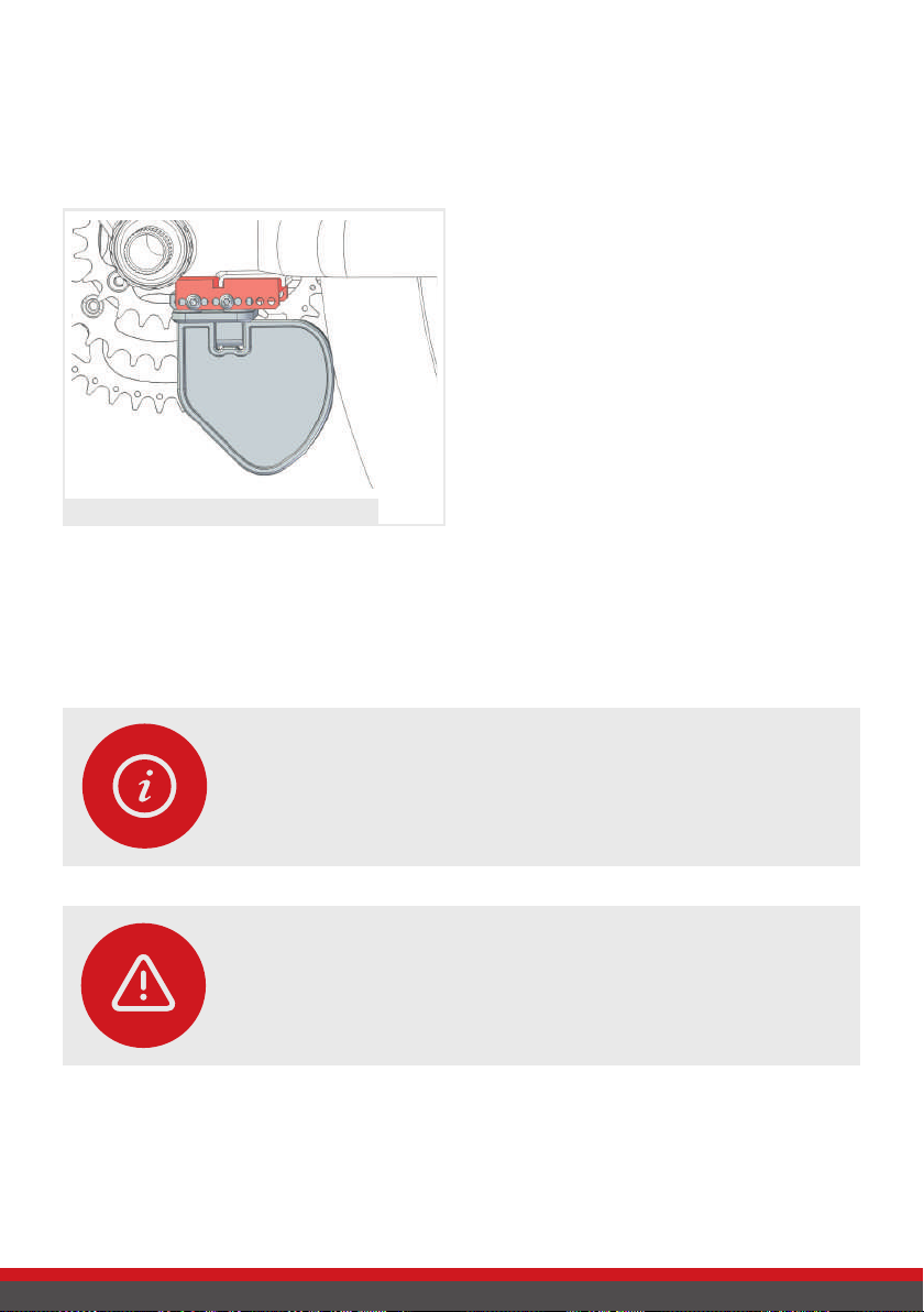
Page 12
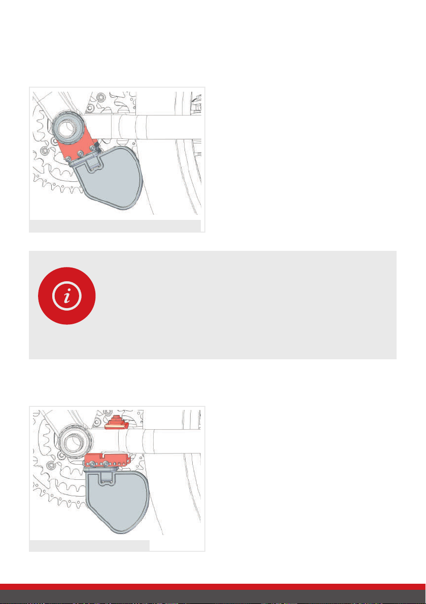
1. Place the damper plate in the stand
plate and attach the setting gauge.
2. The damper plate can be moved along
the stand plate so that the distance
between the setting gauge and the
rear wheel can be adjusted. Slide the
damper plate towards the rear wheel
until the setting gauge rests against
the tyre.
3. Ideally, it should be possible to tighten
three, but at least two M4 Torx screws
on each side in order to continue
installing the drive unit with the side-
stand mounting plate. - See p. 14.
If this is not possible, another installa-
tion variant will have to be used.
The setting gauge is touching the rear wheel
Variant1 1: Installation at the side stand
If your bike has a side stand mounting, it can be used to install the drive. Make sure
that the side-stand mounting is sufficiently far away from the rear wheel and at a
suitable angle to the rear wheel hub. You can check this as follows:
ATTENTION!
If the angle is not correct, you can adjust it by using an underlay for
the stand plate. You can use aluminium or plasc plates or similar for
this purpose. See p. 15.
PLEASE NOTE!
The shape of the frame may prevent the seng gauge from coming
into contact with the rear wheel. If this is the case, rotate the stand
plate for 180°.
Page 13
Variant 2: Installation at the bottom bracket
When fitting the drive unit to the bot-
tom bracket, the short assembly arms
should preferably be used. If the distan-
ce to the tyre is too great, the included
long assembly arms may be used.
This installation variant is not suitable
for bikes with pressfit bottom brackets.
With screwed-in bottom brackets, you
can continue the bottom bracket instal-
lation variant. See p. 16.
The installation at the bottom bracket should be choosen if the bike does not have
a side-stand mounting plate or if cable pulls or limited space conditions do not
allow any other installation variant.
Variant 3: Installation with the Hebie counterplate
The drive unit is fitted by using the Hebie
counterplate if neither Variant 1 nor Va-
riant 2 can be used. Particular attention
needs be paid to ensuring that there is
sufficient space. For a detailed descrip-
tion see p. 20.
The Hebie counterplate is not included
in the installation kit, but can be bought
in our online shop at www.add-e.at/shop
or from your local specialist retailer.
PLEASE NOTE!
In some cases the le bearing shell has no ange or is made of
plasc. In the case of plasc boom bracket shells, the distance
between the motor and the rear wheel can change/increase over
me. For a safe and durable installaon, metal bearing shells with
a ange on both sides should be used. A suitable selecon can be
found in our online shop at www.add-e.at/shop.
Bottom bracket assembly with short assembly arms
Fitting with the Hebie counterplate
Page 14
seCTion 2: asseMbling The KiT
After checking which installation variant is suitable, you can start assembling the
installation kit.
Step 1: Attaching the damper plate
The following describes all three installation variants for attaching the damper plate.
Depending on your bike type one of the three variants can be used.
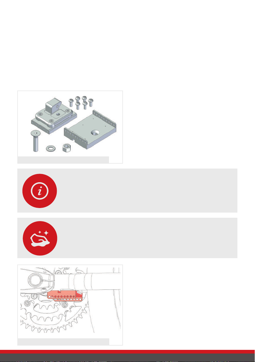
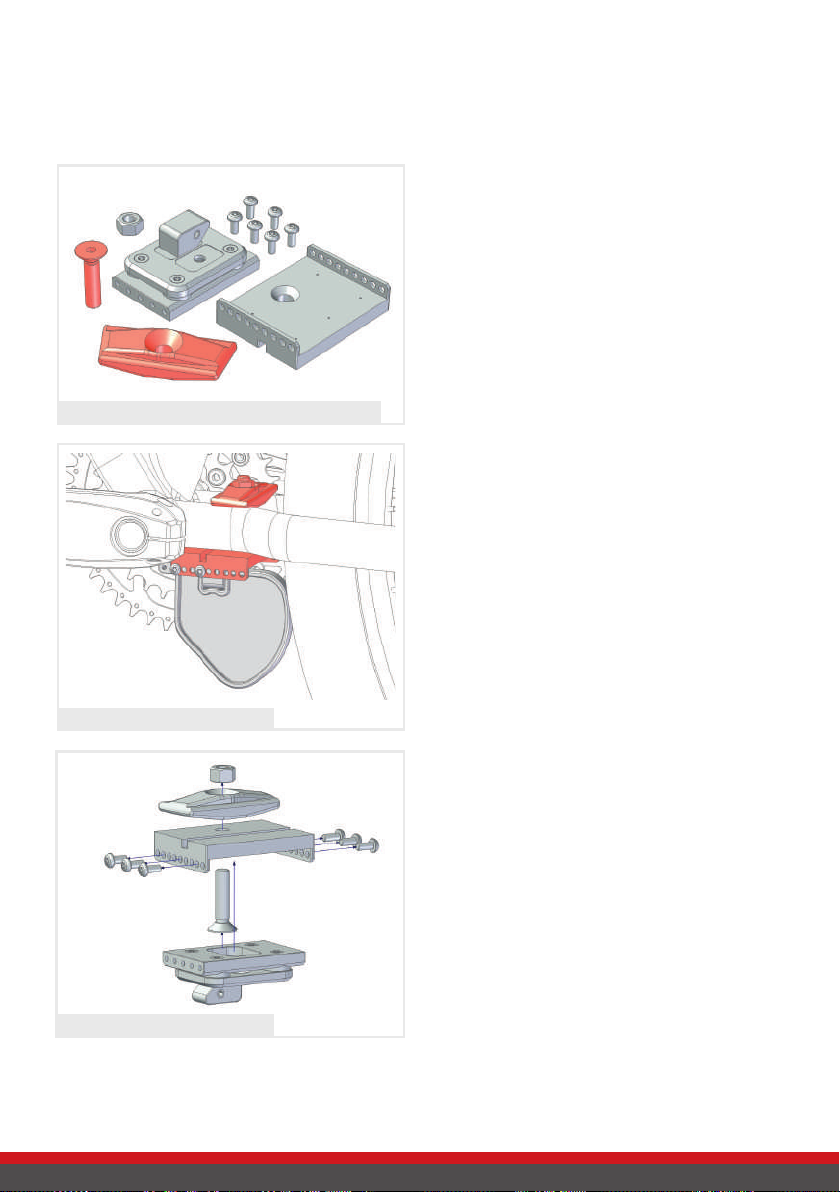
1.1. Variant 1: Installation at the side stand mount
Parts needed:
• Damper plate
• Stand plate
• 6x M4 Torx screws, short
• 1x M8 Allen Screw
• M8 nut
• Washer
Parts needed for installation at side stand mount
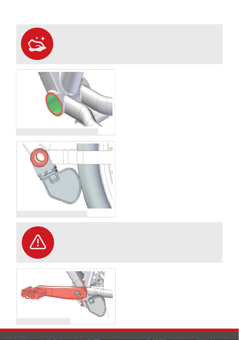
CLEANLINESS!
Before aaching the stand plate, the side stand mount needs to be
thoroughly cleaned!
PLEASE NOTE!
If your bike has a side stand, remove it and switch to a rear stand if
needed. A rear stand can be purchased in our online shop at
www.add-e.at/shop or from a specialist bike retailer.
Stand plate attached to the side stand mount
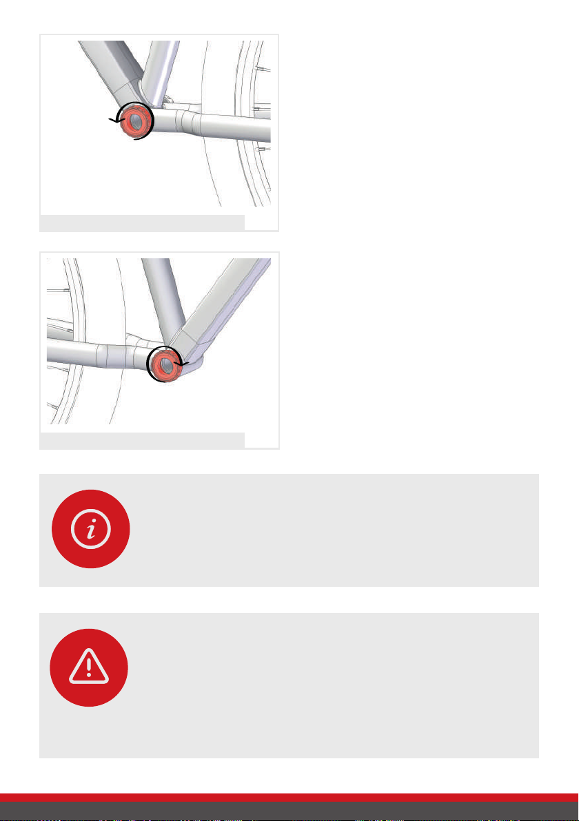
1. Attach the stand plate below the side
stand mount. Insert the M8 Allen
screw from below and fasten it from
above with the washer and the M8
nut.
2. Slide the damper plate onto the stand
plate with the wedge facing the chain
ring and attach the setting gauge with
the curve facing the rear wheel.

Page 15
3. Slide the damper plate back and
forth along the stand plate until the
setting gauge rests against the rear
wheel.
If there is not enough space due to the
shape of the bike, the stand plate can
be rotated fo 180° to gain more space.
Setting gauge is touching the rear wheel
p
PLEASE NOTE!
In order to be able to adjust the drive unit opmally aferwards, the
angle from the stand plate to the rear wheel hub may need to be
adjusted.
The angle needs to be adjusted so that
the extended line of the stand plate
extends to at least the centre or slightly
above the rear wheel hub.
Underlaying the stand plate
Adjust the stand plate angle
If you cannot set the right angle, you can
adjust it by underlaying the stand plate.
For example, aluminium or plastic plates
can be used as an underlay.
4. If the damper plate setting is appro-
priate, attach it to the stand plate using
six M4 Torx screws (ideally three, but at
least two screws on each side).
Mounting the damper plate to stand plate

Page 16
1.2. Variant 2: Bottom bracket installation with assembly arms
Parts needed:
• 1x Damper plate
• 2x Assembly arms, short
• 2x assembly arms, long (optional)
• 6x M4 Torx screw, short
Parts needed for bottom bracket installation
PLEASE NOTE!
To t the drive unit to the boom bracket special bike tools are nee-
ded. These can be ordered in our online shop at www.add-e.at/shop.
The following steps should only be done by experienced installers.
1. Loosen the two screws on the clamp
of the left pedal crank.
Remove the locking screw on the
pedal crank and then pull the crank
off the shaft.
1.2.1. Dismantling the cranks and removing the bottom bracket
Depending on the model and manufacturer, your bike may be equipped with diffe-
rent bottom brackets and cranksets.
The following describes the installation using a Shimano Hollowtech II bottom bra-
cket as an example. This procedure may vary considerably depending on bike type.
Disassembly of the left pedal crank
2. Pull the right-hand pedal crank out
of the bottom bracket.
It may be need to loosen the shaft by
gently tapping on it.
3. Remove the bike chain from the
chainring.
Disassembly of the right pedal crank
Page 17
PLEASE NOTE!
Some Italian and French frame manufacturers are an excepon,
and have both right-hand threads. If you cannot loosen a boom
bracket, heang the frame with a hot air gun in this area helps.
4. Unscrew and remove the left bottom
bracket shell.
Disassembly of the left bottom bracket shell
5. Unscrew and remove the right bot-
tom bracket shell.
The chain ring side thread for the
bottom bracket is a left-hand thread.
Disassembly of the right bottom bracket shell
ATTENTION!
In some cases the le bearing shell has no ange or is made of
plasc. In the case of plasc boom bracket shells, the distance
between the motor and the rear wheel can change/increase over
me. For a safe and durable installaon, metal bearing shells with
a ange on both sides should be used. A suitable selecon can be
found in our online shop at www.add-e.at/shop

Page 18
1. Attach the short assembly arms to
each side of the stand plate using the
six M4 Torx screws supplied.
1.2.2. Assembling the damper plate
When fitting the drive unit to the bottom bracket, preferably the short assembly
arms should be used. Check whether the bike's frame allows this as follows:
Assembling the damper plate
2. Place the setting gauge on the as-
sembled damper plate and point the
wedge on the damper plate towards
the chain ring.
Loosely attach the assembly arms to
the bottom bracket using the bottom
bracket shells.
The setting gauge should rest against
the rear wheel. If this is not the case,
use the long assembly arms.
Short assembly arms - right lenght
p
ATTENTION!
If the distance between the seng gauge and the rear wheel is too
large, use the long assembly arms! However, if these are too long,
the stand plate angle for ng the drive unit will be too acute.
Right ng later on is not possible.
Short assembly arms too short Long assembly arms too long
Page 19
1.2.3. Attaching the damper plate to the bottom bracket
CLEANLINESS!
Before aaching the damper plate, thoroughly clean the area around
the boom bracket. There should be no dirt or grease between the
assembly arms and the frame.
1. To improve the grip of the assembly
arms, some assembly paste can be
applied to the contact surfaces on
the bottom bracket.
For this purpouse, apply a thin layer
of paste to the frame, making sure
that it does not enter inside the
frame.
Thin layer of assembly paste on the frame
2. Pre-fix the damper plate to the frame
with the appropriate assembly arms
and the two bottom bracket shells.
Press the setting gauge against the
tyre. Before alternately tightening the
bottom bracket shells, make sure that
the extended line of the damper plate
extends to at least the centre of the
rear wheel hub or slightly above it.
See p. 15.
Tightening the bottom bracket shells
3. Replace the pedal cranks in reverse
order.
See p. 16.
Make sure that everything is tight-
ened securely.
Mount the pedal cranks
ATTENTION!
When ghtening the boom bracket, make sure that the seng
gauge does not slip out of place and remains in contact with the
tyre! Tighten the boom bracket shells alternately.
Page 20
1.3. Variant 3: Installation with the Hebie counterplate
Parts needed:
• Hebie counterplate (not included in
standard delivery)
• Damper plate
• Stand plate
• 6x M4 Torx screws
• 1x M8 Allen screw
• M8 cap nut
Fitting the drive unit with Hebie counterplate is done when weather the side stand
nor bottom bracket variants are suitable. Particular attention needs to be paid that
there is sufficient space.
Parts needed for Hebie counterplate installation
Attaching the Hebie counterplate
1. Insert the stand plate between the
rear wheel struts with the M8 bolt
inserted.
2. Attach the Hebie counterplate from
above and tighten it with the M8 cap
nut.
3. Slide the damper plate with the set-
ting gauge attached along the stand
plate towards the rear wheel until it
rests against the tyre.
4. Tighten the damper plate with at
least 2 screws on each side, making
sure the wedge is pointing towards
the chainring, and the setting gauge
is resting against the tyre.
Attaching the Hebie counterplate
With installation variant 3, the stand
plate is attached to the frame with the
Hebie counterplate.
For a detailed description of how to
attach the stand plate, refer to the inst-
ructions for fitting the drive unit to the
side-stand mounting. See p. 14.
Table of contents
Other e-motion Bicycle Accessories manuals


