AUFBAUANLEITUNG RAHMEN/ ASSEMBLY INSTRUCTIONS FRAME
1. WÄHLEN SIE DIE EINLEGETIEFE DER MATRATZE (SEITE 4). SOLLTEN SIE DIE EINLEGETIEFE 01 ODER 03 WÄHLEN, SCHRAUBEN SIE DIE AUFLAGE-
LEISTEN DER SEITENTEILE (B) AB UND VERSETZEN DIESE NACH OBEN BZW. NACH UNTEN UND SCHRAUBEN DIESE IN DIE VORGEBOHRTEN
LÖCHER. /
CHOOSETHE INSERTION DEPTH FOR YOUR MATTRESS (PAGE 4). SHOULDYOU CHOOSE DEPTH 01 OR DEPTH 03, UNSCREW SUPPORT BEAMS
FROMTHE SIDE PIECES (B) AND MOVE UP OR DOWN TO SUIT MATTRESS DEPTH. SCREW INTO EXISTING HOLES TO FIT.
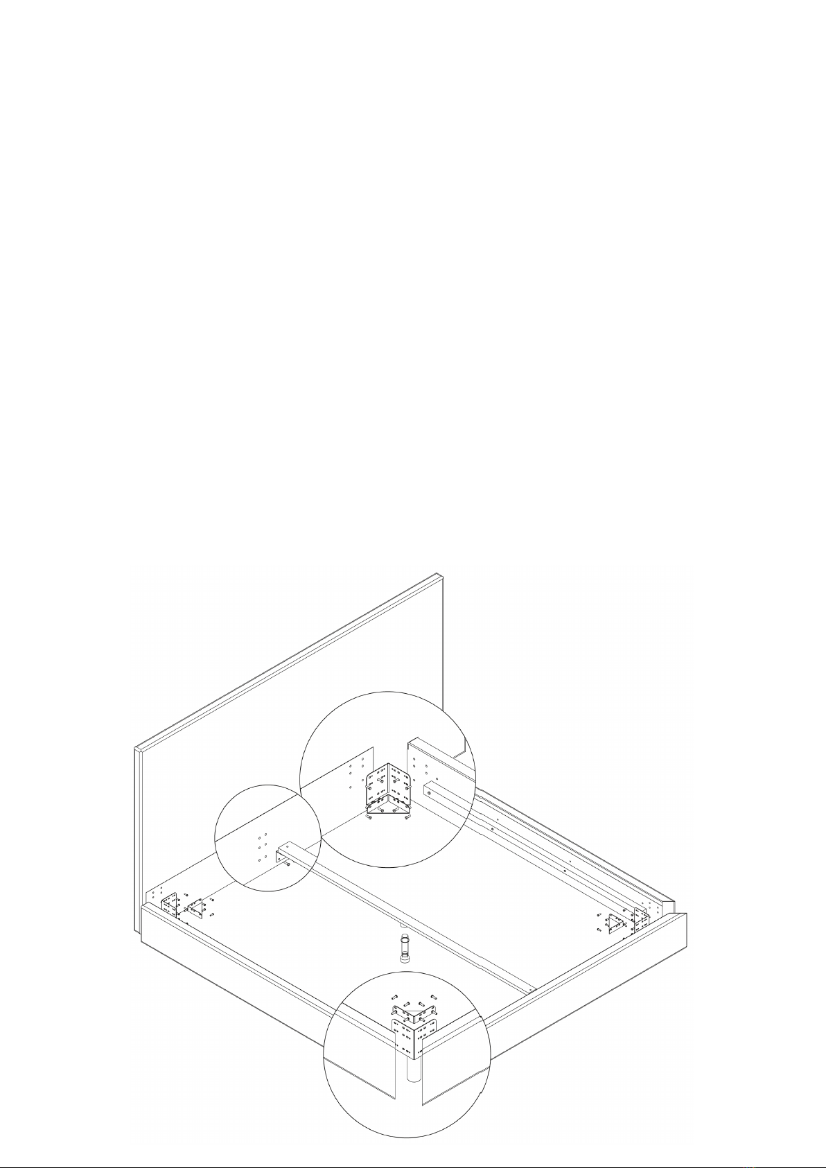
2. MONTIREN SIE DIE ECK-AUFLAGEWINKEL (E1) MIT DEN SCHRAUBEN (M6 x 25 MM) AN DIE BETT-SEITENTEILE (B). /
FIT CORNER SUPPORT RESTS (E1) TO BED SIDE PARTS (B) USING SCREWS (M6 X 25 MM).
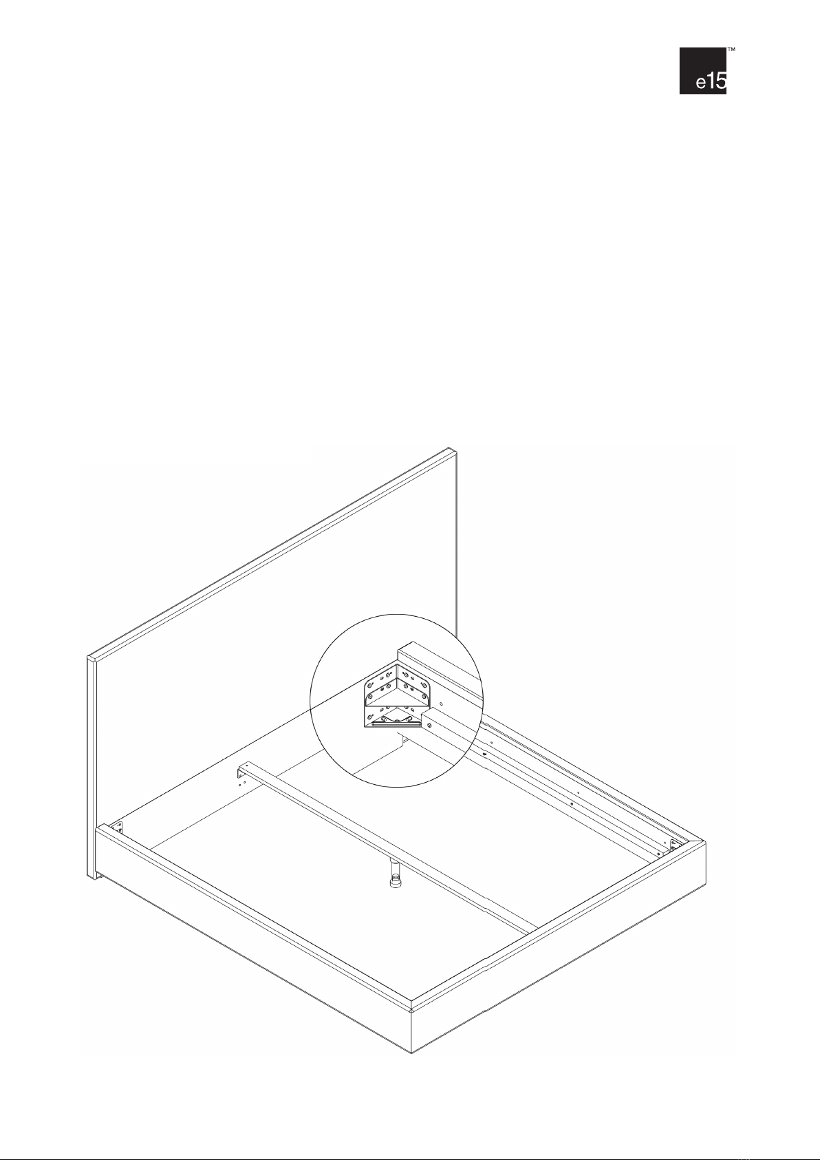
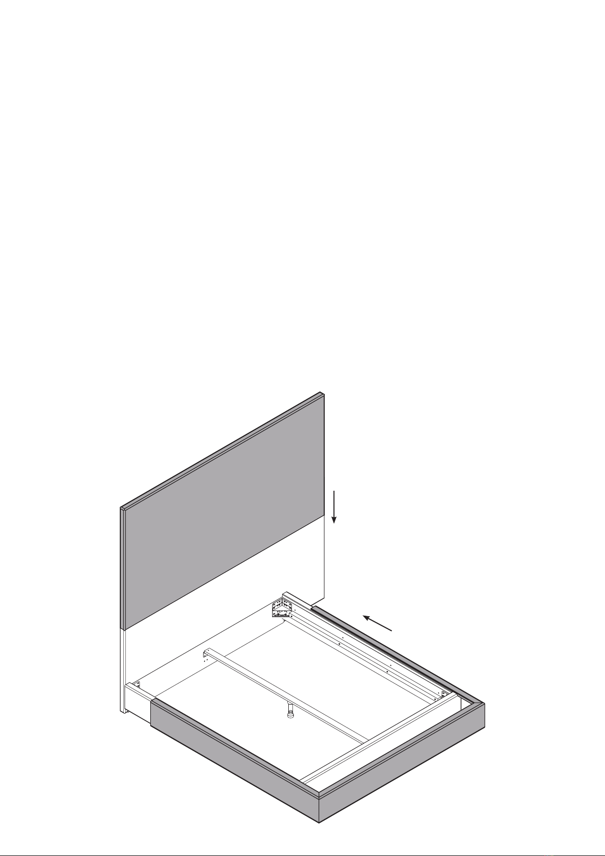
3. DIE BETT-SEITENTEILE (B) VERBINDEN SIE NUN ZUNÄCHST MIT DEM KOPFTEIL (A). /
CONNECT BED SIDE PIECES (B) TO HEADPIECE (A) FIRST.
4. SCHRAUBEN SIE DIE HOLZFÜSSE (G) MIT DEN SCHRAUBEN (M8 x 25 MM) AN DIE BEIDEN VORDEREN ECK-AUFLAGEWINKEL (E1). /
NOW FIT WOODEN FEET (G) WITH SCREWS (M8 X 25MM) TO FRONT TWO CORNER SUPPORT RESTS (E1).
5. MONTIEREN SIE DAS FUSSTEIL (C). / FIT FOOT PIECE (C).
6. JE NACH GEWÄHLTER EINLEGETIEFE DER MATRATZE MONTIEREN SIE DIE ZUSÄTZLICHEN ECKAUFLAGEWINKEL (E2) WIE AUF SEITE 4 IM DETAIL
GEZEIGT. SOLLTEN SIE DIE EINLEGETIEFE 01 GEWÄHLT HABEN, BENÖTIGEN SIE DIE ZUSÄTZLICHEN ECKAUFLAGEWINKEL (E2) NICHT. /
DEPENDING ON YOUR CHOSEN INSERTION DEPTH OF MATTRESS, FIT REMAINING CORNER SUPPORT RESTS (E2) ACCORDINGLY AS SHOWN IN
DETAIL ON PAGE 4. IF YOU HAVE CHOSEN MATTRESS INSERTION DEPTH 01, YOU WILL NOT NEED THE REMAINING CORNER SUPPORT RESTS (E2).
7. MONTIEREN SIE NUN, JE NACH GEWÜNSCHTER MATRATZEN-EINLEGETIEFE, DIE AUFLAGEWINKEL (F) FÜR DIE MITTELAUFLAGELEISTE (D) AN
KOPF- UND FUSSTEIL. /
SCREW SUPPORT RESTS (F) FOR MID SUPPORT BEAM (D) TO HEAD AND FOOT BOARD, ACCORDINGTO PREFERRED MATTRESS INSERTION DEPTH.
8. STECKEN SIE DEN EINSTELLFUSS (H) IN DAS GEGENSTÜCK DER MITTELAUFLAGELEISTE. MIT DEN SCHRAUBEN (M6 x 15 MM) MONTIEREN SIE
NUN DIE MITTELAUFLAGELEISTE (D) AUF DEN AUFLAGEWINKELN (F). /
FIT ADJUSTABLE FOOT (H) TO COUNTER-PART OFTHE MID SUPPORT BEAM. USINGTHE SCREWS (M6 X 15MM) FIT MID SUPPORT BEAM (D) ON TO
SUPPORT RESTS (F).
SL05 PARDIS
BETT / BED
DESIGN: PHILIPP MAINZER, 2007
Aufbauanleitung Rahmen / Assembly instructions frame
1. Wählen Sie die Einlegetiefe der Matratze (Seite 4). Sollten Sie die Einlegetiefe 01 oder 03 wählen, schrauben Sie die Auflageleis-
ten der Seitenteile (B) ab und versetzen diese nach oben beziehungsweise nach unten. Schrauben Sie sie in die vorgebohrten Löcher. /
Choose the insertion depth for your mattress (page 4). Should you choose depth 01 or 03, unscrew support beams from the side
pieces (B) and move up or down to suit mattress depth. Screw into existing holes to fit.
2. Montieren Sie die Eck-Auflagewinkel (E1) mit den Schrauben (M6 x 25 MM) an die Bett-Seitenteile (B). /
Fit the corner support rests (E1) to bed side parts (B) using screws (M6 x 25 MM).
3. Die Bett-Seitenteile (B) verbinden Sie nun zunächst mit dem Kopfteil (A). /
Connect bed side pieces (B) to headpiece (A) first.
4. Schrauben Sie die Holzfüsse (G) mit den Schrauben (M8 x 25 MM) an die beiden vorderen Eck-Auflagewinkel (E1). /
Now fit wooden deet (G) with screws to front two corner support rests (E1).
5. Montieren Sie das Fussteil (C). / Fit foot piece (C).
6. Je nach gewählter Einlegetiefe der Matratze montieren Sie die zusätzlichen Eckauflagewinkel (E2) wie auf Seite 4 im Detail
gezeigt. Sollten Sie die Einlegetiefe 01 gewählt haben, benötigen die die zusätzlichen Eckauflagewinkel (E2). /
Depending on your chosen insertion depth of mattress, fit remaining corner support rests (E2) accordingly as shown in detail on
page 4. If you have chosen mattress insertion depth 01, you will not need the remaining corner support rests (E2).
7. Montieren Sie nun, je nach gewünschter Matratzen-Einlegetiefe, die Auflagewinkel (F) für die Mittel-Auflageleiste (D) an Kopf- und
Fussteil. /
Screw support rests (F) for mid support beam (D) to head and foot board, according to prefered mattress insertion depth.
8. Stecken Sie den Einstellfuss (H) in das Gegenstück der Mittelauflagenleiste. Mit den Schrauben (M6 x 15MM) montieren Sie nun
die Mittelauflageleiste (D) auf den Auflagewinkel (F). /
Fit adjustable foot (H) to counter-part of the mid support beam. Using the screws (M6 x 15MM) fit mid support beam (D) on to
support rests (F).
WWW.E15.COM