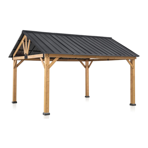
Eagle Peak WG120-BLK User manual

Thank you for choosing Eagle Peak !
EAGLE PEAK 11 FT X 13 FT
Steel Roof Wood Gazebo
INSTRUCTION MANUAL

LIMITED WARRANTY
Global Shade Corporation offers a limited warranty that this product is free from defects in materials
and workmanship for a period of one (1) year from the original date of purchase. At its discretion, Global
Shade Corporation may provide replacement parts for defective parts to original purchaser after its
own review and examination. Original receipt or proof of purchase as well as proof of defect is required.
Global Shade Corporation will not be responsible for shipping costs incurred outside the continental
USA. Warranty is valid for the original purchaser for 1 year from the date of purchase and is not
transferable. Regular maintenance of wood, aluminum, and steel components is required to assure the
integrity of your product and is a requirement of the warranty. This warranty does not cover any
inspection costs.
This Limited Warranty does not cover:
•Labor for replacement of any defective item(s);
•Incidental or consequential damages;
•Cosmetic defects which do not affect performance or integrity;
•Vandalism; improper use or improper installation; acts of nature, including but not limited to wind,
storms, hail, floods, excessive water exposure;
•Structural or component failure due to snow loading.
•Minor twisting, warping, checking, cracking, or any other natural occurring properties of wood that do
not affect performance or integrity.
Global Shade Corporation’s products have been designed for safety and quality. Any modifications
made to the original product could damage the structural integrity of the product leading to failure and
possible injury. Global Shade Corporation cannot assume any responsibility for modified products.
Furthermore, modification voids any and all warranties.
All replacement products or parts will assume the remaining warranty of the original product. This
warranty gives you specific legal rights. You may also have other rights, which vary from state to state.
This product is warranted for RESIDENTIAL USE ONLY. Global Shade Corporation disclaims all
other representations and warranties of any kind, express or implied.
Global Shade Corporation does not warrant against and under no circumstances shall Global
Shade Corporation be liable or responsible for any personal loss, injury, or direct or indirect
incidental or consequential damages resulting from the use of this product
This Warranty gives you specific legal rights. You may have other rights as well which vary from state to state
or province to province. This warranty excludes all consequential damages, do not allow the limitation or
exclusion of consequential damages, and therefore this limitation may not apply to you, however, some
states/provinces do not allow the limitation or exclusion of consequential damages, and therefore this
limitation may not apply to you.
1

To reduce the risk of serious injury, read the following safety instructions thoroughly
before assembling and using the gazebo.
•Check with your local governing authority/local municipal codes regarding installation and permitting
of such structures before assembly.
•Use of personal protective equipment including gloves, safety glasses, and closed toe footwear is
recommended during assembly.
•Requires two or more people to assemble and install safely and correctly.
•The product is required to be installed on level solid surface and is not intended for unsecured use. The
gazebo is to be anchored to the surface with appropriate bolts or anchors. These anchors need to be
purchased separately for the specific installation surface. Do not assemble the gazebo on soil, earth, or
bare ground.
•Ensure enough clearance around the product. Before assembling the product, find level ground no less
than 6' (1.8 m) away from any structures or obstructions, such as fences, buildings, or overhead
obstacles.
•Do not assemble or install the gazebo underneath electrical lines or above underground utilities.
•Check for underground utilities before digging or driving stakes into the ground.
•This gazebo is not to be regarded as part of a building/house structure.
•All assembly and maintenance of the product must be carried out by adults only.
•Use all power tools and hand tools in accordance with their respective safety manuals.
•Keep children and pets away while setting up the gazebo.
•Wood framed gazebos are NOT flame retardant and will burn. Grills, firepits, and chimneas create a fire
hazard and should not be placed under or near your structure.
•Do not hang heavy weights from the roof frame.
•Do not climb onto the roof of the gazebo for any reason.
•Check all nuts and bolts monthly to ensure bolts/nuts are tightened.
•Check the metal hardware monthly to ensure there are no exposed sharp edges or rust. Sand sharp
edges or rust with sandpaper and apply touch up paint. Always use lead free paint that conforms to 16
CRF Part 1303.
•Inspect wood parts monthly. Sand any lifted grain or splinters and apply a sealant over the raw wood.
The wood frame is subject to weathering. As with all outdoor wood product, it is necessary to apply a
wood sealant to the wood frame to prevent premature weathering.
WARNING:
Needed for assembly: (The following tools are not included)
Drill Tape Measure Hammer Screwdriver Ladder
Level Framing Square Two or more people
2

Part List
3
Description Sketch
Peak Rafter
Connector
Corner Rafter
Connector R
Corner Rafter
Connector L
Base
Base Cover
Corner Brace 2
Corner Brace 1
Post
Inner Long
Beam (Long)
Inner Short
Beam (Short)
Inner Middle Beam
Outer Long Right
Beam (Short)
Outer Long Left
Beam (Short)
Label
C4
C2
C1
C
B
11
10
08
07
06
05
04
03
QTY
2
2
2
4
4
4
4
4
Rafter Support
Beam
Rafter Support
Middle Beam
Rafter Support
Angled Beam
15
14
13
4
2
4
4
4
4
2
2
Outer Long Right
Beam (Long)
Outer Long Left
Beam (Long)
02
01
2
2

Part List
4
I
O
M2
M1
L3
L1
J1
Rafter Lower
Connector
Rafter Connector
Brace
Roof Side Support
Bar 2
Roof Side Support
Bar 1
Eave Bar 3
Eave Bar 1
Support Brace
6
HRafter 6
8
PHook 1
P1 Large Roof Panel 10
2
NRafter Connector 16
2
2
L4 Eave bar 4 2
2
L2 Eave Bar 2 2
3
Description SketchLabel QTY
Ridge Beam 2
Ridge Beam 1
F2
F1
1
1
G1 Ridge Beam
Connector 1 1

Part List
5
P2 Small Roof Panel 4
Description SketchLabel QTY
QEave Roof Bar 6
S
R2
R1
Steel Pin
Ridge Cover 2
Ridge Cover 1
12
1
U
T
Roof Side Bar
Rafter Support Brace
4
2
2

6
Hardware List
Description
AA
CC
KK
II
EE
FF
HH
8
72
24
16
72
108
16
Hex Head Bolt
M10x205
BB 140
Flat Washer
M6
Self-tapping Screw
M5x40
DD 12
Nut
M6
LL 8
Nylon Locking Nut
M10
MM 84
Washer
M8
Self-tapping Screw
M5x30
Hex Head Bolt
M6x15
Hexagon Socket Bolt
M8x35
Hexagon Socket Bolt
M8x20
Self-tapping Screw
M8x35
JJ 12
Hex Head Bolt
M6x55
SketchLabel QTY

7
Description
PP
QQ
RR
Z2
Z4
Z1
8
8
2
1
2
2
Stake
Φ8x180
Hex Head Bolt
M6x35
UU 14
Nylon Lock Nut
M8
Drill
M3
Allen Key
M8
Wrench
M10
Z3 2
Wrench
M8
Wrench
M6
SketchLabel QTY
Hardware List
0 1 2 3 4 5 6 7 8
NN 24
Washer
M10
OO 8
Hex Head Screw
M10x80
WW 14
Hex Head Bolt
M8x50

Step 1 Attach Post Base and Cover
8
16X
M5x30
4X
08
4X
B
EE
4X
C
08
BB
08
CC
EE
EE
08
08
08
08
●Slide Base Cover (B) onto Post (08) so open side is towards bottom of post.
●Place Base (C) on end of Post (08) and secure with 4 Screw (EE) as shown.

Step 2 Assemble Inner Beams
9
● Assemble Short Inner Beams using 1 Inner Middle Beam (05) and 2 Inner Short Beams (06)
as shown. Repeat for second Short Inner Beam.
● Assemble Long Inner Beams using 1 Inner Middle Beam (05) and 2 Inner Long Beams (07)
as shown. Repeat for second Long Inner Beam.
4X
05
4X
06
4X
07
16X
M8x20
16X
M8
KKMM

Assemble Outer Short Beam
2X
03
2X
04
● Align end of Outer Short Left Beam (03) and Outer Short Right Beam (04). Place Rafter
Support Brace (T) over the joint. Use 2 of Screw (KK) and Washer (MM) to assemble.
Step 3
10
4X
M8x20
4X
M8
KKMM
2X
T

Assemble Outer Long Beam
2X
01
2X
02
Step 4
11
4X
M8x20
4X
M8
KKMM
● Align end of Outer Long Left Beam (02) and Outer Long Right Beam (01). Use
2 of Screw (KK) and Washer (MM) to assemble.

Final Beam Assembly
72X
M5x40
CC
06
05
06
04 03
05
02 01
07 07
Step 5
12
● Stack the Inner Short Beam and Outer Short Beam so the Rafter Support Brace (T) is facing down. The
predrilled holes on the Inner Short Beam should be facing up.
● Align the large drilled holes at the ends of the Short Beams. Secure the Inner Short Beam to the Outer
Short Beam using 14 of Screw (CC) at the predrilled locations as shown. Repeat procedure on the other
Short Beam.
● Turn the Short Beam Assemblies over and use 4 of Screw (CC) through the four side holes in each
Rafter Support Brace (T).
● Stack the Inner Long Beam and Outer Long Beam as shown. Align the large drilled holes at each end.
Secure the Inner Long Beam to the Outer Long Beam using 18 of Screw (CC). Repeat procedure on
other Long Beam.

Attach Long Beams to Posts
●Arrange 2 of Post (08) Approximately 12ft apart. Orient so the side
with the predrilled hole closest the top is facing up. Prop the end of
the Post up off the ground so that you will be able to hold a nut on
the bottom side in the next steps.
● Lay a Long Beam Assembly on the posts so the angled end cuts face
the post.
● Align the holes in the Long Beam Assembly with the Post.
● Insert a Bolt (AA) with Washer (NN) through the hole in the Beam and Post. Use a Washer (NN) and Nut
(LL) on the opposite side. Make snug, but do not tighten yet.
● Using a Framing Square, ensure that each Post is at a 90 degree angle to the Beam. Insert a Bolt (OO)
into the bottom hole in the Beam. Screw until tight. Repeat at opposite end.
● Tighten Bolt (AA) securely on each end.
●Repeat process to other Long Beam and Post Assembly.
4X
M10x205
AA
4X
M10x80
OO
12X
M10
NN
4X
M10
LL
Step 6
13
08
08
90 degrees
AA
AA
OO
OO
NN
NN
LL
LL
NN
NN
NN
NN
01
01
01
07
07
07
07
07
02
Rt=90⁰
02 07
05
05
02
08
08
08

● Stand and temporarily secure the Post and Long Beam Assemblies in proper location. Use of braces
(not included) or additional help may be required for this step.
● Lift a Short Beam Assembly into place, position Rafter Corner Connectors (C1) and (C2)as shown and
install a Bolt (AA) and Washer (NN) at the lower hole at each end and tighten.
● Use the framing square and level to ensure the Post is plumb and at a 90 degree angle to the beam.
● Install Screw (OO) with Washer (NN) in upper hole and tighten securely.
● Repeat procedure at opposite end.
● Check diagonal measurement to ensure the frame is square.
12X
M10
NN
4X
M10
LL
Attach Short Beams to Posts
4X
M10x205
AA
4X
M10x80
OO
Step 7
14
2X
C1
2X
C2
Rt=90

Before proceeding with
Step 8 ensure that the
frame is square by ensuring
the diagonal dimensions
are identical, the beams are
level and that the posts are
at 90 degree angles to the
beams and are plumb.
16X
M8x35
II
16X
M8x35
HH
32X
M8
MM
● Install Corner Braces at 8 locations using 4pcs Corner
Brace (10) and 4pcs Corner Brace (11). Use two Bolts
(HH) with Washer (MM) to secure the top of each
arch support.
● Use the framing square to ensure each Post remains
at a 90 degree angle to the Short Beam and Long
Beam. Secure the bottom of each Arch Support to
the Posts using 2pcs Screw (II) at each location.
138.5 in
116.0 in
180.9 in
180.9 in
d1=d2
i
d1
d2
Rt=90°
Important
Step 8
15
4X
10
4X
11
Post Brace Installation
Rt=90° Rt=90°

4X
13
2X
14
4X
15
2X
C4
12X
S
16X
M5x30
EE
Gable Support Assembly
12X
M10
NN
6X
M10
LL 6X
M10x50
WW
● Attach Rafter Support Beams (14), one piece, and (15), two pieces, to the Rafter Support Brace (T) using
3 pcs Bolt (WW) with Washers (MM).
● Insert 6 Pins (S) into the drilled holes in the tops of Supports (14) and (15).
● Position 2pcs Rafter Beam (3) as shown, aligning the Pins in Supports (14) and (15) with the holes on
the underside of each Beam (13).
● Position Peak Rafter Connector (C4) at the peak with the tab oriented at the outside of the frame.
Secure to Beams (13) with a total of 8pcs Screw (EE).
● Secure the lower ends of Beam (13) to Corner Rafter Connector (C1) and (C2) using a total of 4pcs Bolt
(WW), 8pcs Washer (MM), and 4pcs Nut (UU).
● Repeat to opposite end.
Step 9
16

● Slide Ridge Beam Connector (G) into the end of Ridge Beam 1 (F1). Align the holes and insert 2pcs
Screw (FF) with Washers (BB).
● Slide the end of Ridge Beam 2 (F2) over Connector (G) and align the holes. The ends of Ridge Beam
(F1) and Ridge Beam (F2) should touch in the middle. Secure Ridge Beam 2 (F2) with 2pcs Screw (FF)
with Washers (BB).
● Tighten all Screws (FF) securely.
4X
M6
BB
Step 10
17
4X
M6x15
FF
Ridge Beam Assembly
1X
F1
1X
F2
1X
G1

Step 11
18
1X
● Place the Ridge Beam Assembly on top of the frame. The ends will fit in and be held by Peak Rafter
Connector (C4).
● Secure the Ridge Beam Assembly to Peak Rafter Connector (C4) using 2pcs Bolt (FF) and Washer (BB).
Ridge Beam Placement
2X
M6
BB 2X
M6x15
FF

Step 12
19
6X
H
6X
I
Roof Rafter Assembly
12X
M6x55
JJ
36X
M6
BB
12X
M6
DD 12 X
M6x15
FF
● Place 3pcs Rafter Lower Connector (I) on each Long Beam Assembly. Space approximately equally
distant to one another.
● Lift a Rafter (H) into position and secure to the Ridge Beam Assembly using 2pcs Bolt (FF) and Washer
(BB).
● Place the opposite end of the Rafter (H) into the cradle of Rafter Lower Connector (I) and secure with
2pcs Bolt (JJ), 4pcs Washer (BB) and 2pcs Nut (DD).
● Repeat process for the remaining 5pcs Rafters (H) and Rafter Lower Connectors (I).
Table of contents
Other Eagle Peak Outdoor Furnishing manuals
Popular Outdoor Furnishing manuals by other brands

Allen + Roth
Allen + Roth URM819003J-3 quick start guide

Hanover
Hanover GFM30731C manual

Keter
Keter MANOR 4x6S Assembly instructions

Belleze
Belleze 014-HG-14065 owner's manual

Backyard Creations
Backyard Creations 272-1213 Assembly instructions

Amish Country Gazebos
Amish Country Gazebos Wood Gazebo-in-a-Box Assembly instructions

USP
USP DURAMAX 30114-3 owner's manual

Backyard Discovery
Backyard Discovery ASHLAND Owner's manual & assembly instructions

Alice's Garden
Alice's Garden TAVOLA WK150KDR6 manual

Hanover
Hanover TRADDN11PCSW4 manual

Sunnydaze Decor
Sunnydaze Decor IEO-525 manual

vita
vita Classic Regency Trellis VT68198 Assembly guide