eao 09 Series Product information sheet

www.eao.com
Series 09 – I/O Outdoor Keypad
Operating instructions and safety instructions
Operating instructions

www.eao.com 2
Operating instructions and safety instructions
Project
S09, 1707 hardwired
Document Number
1707900703
Document
Description
Operating and safety instructions for the hardwired keypads
EAO Automotive GmbH & Co. KG
Richard-Wagner-Straße 3
08209 Auerbach/Vogtl.

www.eao.com 3
Change History
Version Change Description Status Author Date
01 initial intial MAR 02.06.2021
01 initial reviewed
ESF 13.08.2021
Referenced Documents
Reference Document Number Version Author Date
1707 product information 1707940001 02 EBJ 12.05.2021
Series 09 CAN Keypads I/O - CE-
Certification - Compliancy of EAO
Products
- - HDI July,15,
2021
Related Products
Version
Series 09 I/O Outdoor Keypad
01S

www.eao.com 4
Table of contents
1. Safety warnings....................................................................................................7
1.1 Intended use ........................................................................................................7
2. Proper environment..............................................................................................8
3. General description ..............................................................................................8
4. Technical specification .......................................................................................10
5. Scope of delivery................................................................................................11
6. Storage ..............................................................................................................11
7. Mechanical installation/mounting........................................................................12
7.1 Installation in a panel by means of retaining clamps (retaining clamp version) ...12
7.2 Installation in a panel with self-locking nuts (screw-in version) ...........................13
7.2.1 Mounting sequence............................................................................................13
7.3 Installation of the symbol inserts ........................................................................14
7.4 Use inside closed vehicles .................................................................................15
8. Electrical installation and pinning .......................................................................16
9. Cleaning.............................................................................................................18
10. Optional accessories..........................................................................................18
11. Liability for quality defects ..................................................................................18
12. Service, repair....................................................................................................19
13. Decommissioning, disposal ................................................................................19
14. Declaration of Conformity...................................................................................19

www.eao.com 5
List of abbreviations and units
DIN Deutsches Institut für Normung / German institute for standardization
EN European standard
EU European Union
HMI Human-Machine-Interface
IP International Protection
ISO International Organization for Standardization
LED Light emitting diode
MOT Ministry of Transport
OEM Original Equipment Manufacturer
VDA Verband der Automobilindustrie / German Association of the automotive
industry

www.eao.com 6
Used symbols
Caution!
Indicates a hazardous situation which, if not avoided, may result in a
minor or moderate injury
Attention
Describes information on installation which, if ignored, can lead to
malfunctions
Note
Indicates a situation which, if not avoided, may result in property
damage
Indicates an executive activity
Indicates an application tip

www.eao.com 7
1. Safety warnings
The safe system handling requires knowledge of the operating instructions.
Caution!
Connect the power supply in accordance with the safety regulations
for electrical equipment.
Risk of injury
Damage to the keypad
Note
Avoid shocks and impacts to the keypad during installation
Damage to or destruction of the keypad
The supply voltage must not exceed the specified limit.
Damage to or destruction of the keypad
Protect the connector from damages
Damage to or destruction of the keypad
Intended use
The modules were developed for applications in vehicles with MOT approval within the EU.
The robust, modular design with a protection degree of up to IP6K7 and the possibility of
customer-specific adaptations and the arrangement of keypad symbols are facts that make the
devices the best choice for use in heavy-duty and special vehicles.
The keypads may only be operated within the parameters specified in the technical data.
The keypads must be used in such a way that no persons are endangered, or machines or
other equipment become damaged in the event of failure or malfunction.
Commissioning must be carried out by qualified personnel.

www.eao.com 8
2. Proper environment
See 4 Technical specification.
Note
If possible, avoid abrupt changes in the operating temperature of the
keypad, cable and connector.
Damage to the keypad, connector
Caution!
Do not operate the keypad in:
Potentially explosive atmospheres
Applications where the keypad and connector are completely or partly
submerged for extended periods of time
Situations in which the keypad and connector are subjected to harsh
external shocks and impacts
Do not use for remaining in final customer installations due to
validation not completed
Risk of injury
Damage to the keypad, connector
The design of the keyboard (keys can still be pressed) means that keys are
protected from freezing as long as the keys remain accessible and can be
pressed. This means that the keyboard can also be used in snow and ice.
3. General description
Series 09 Rugged Keypads offer high reliability: The robust, modular design with protection
degrees of up to IP6K7 and the possibility of customer specific adaptations and the
arrangement of symbol inserts predestine the devices for use in heavy-duty and special
vehicles. The modules are as well designed for ECE certification.
Harsh environmental conditions and low back panel depth require a robust and compact
product design. In addition, the control and signalling devices must be precisely configurable
both mechanically and electronically for the respective application. The high-quality Rugged
Keypad meets these requirements with a cutting-edge system integration.

www.eao.com 9
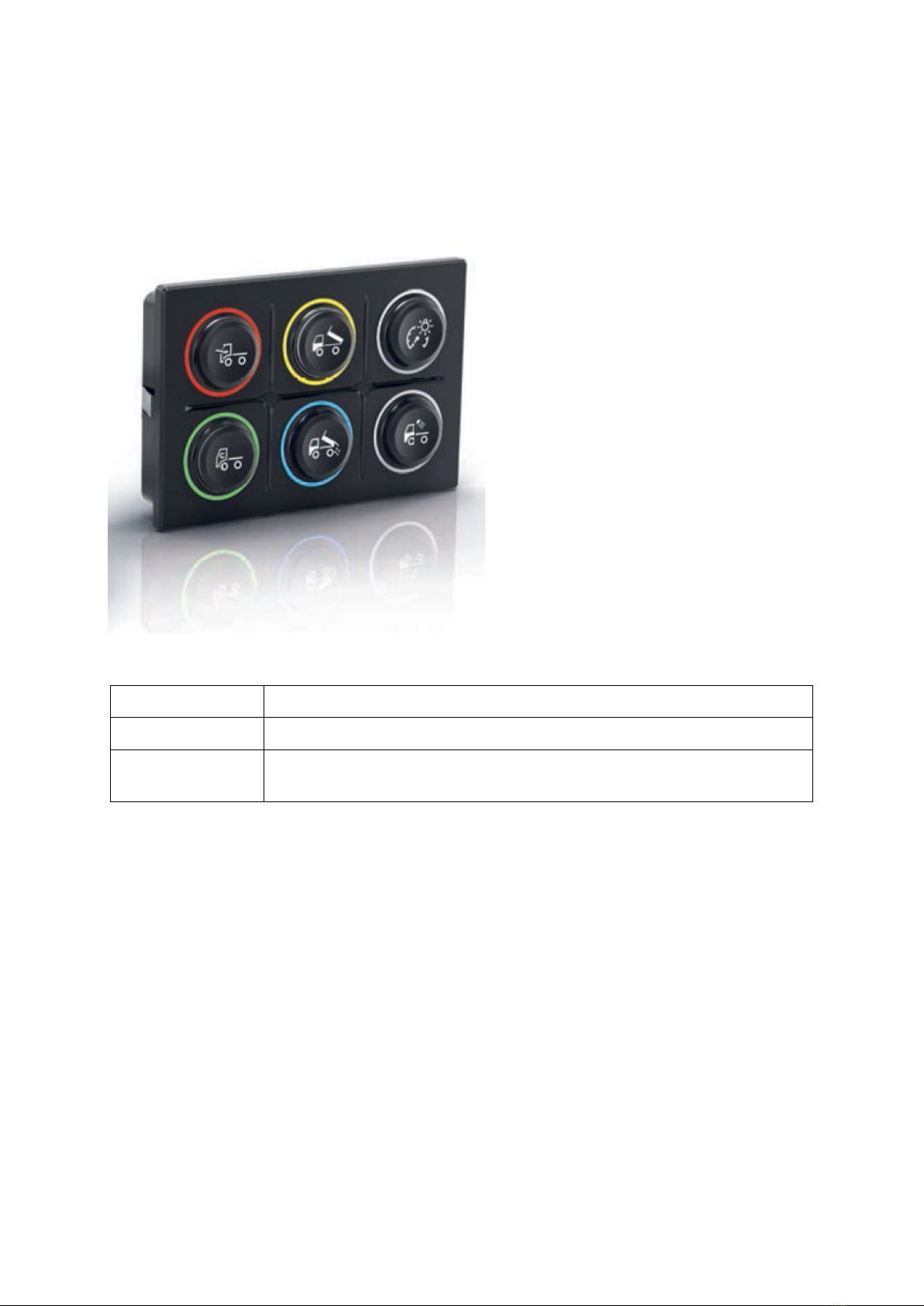
Typical applications
Special vehicles such as fire engines, road sweepers, cleaning vehicles, dustcarts, snow
clearing vehicles and snow groomers. Heavy-duty vehicles such as construction and
agricultural vehicles
Advantages
Red halo ring illumination
Robust, ergonomic and innovative design with a protection degree of up to IP6K7 (front:
IP6K7; back: IP20 without plugged connector). Protection degree for assembled
situation in responsibility of customer application.
Interchangeable symbols according to ISO 7000 or customer-specific symbols
Robust and innovative design
The design of the Rugged Keypads is characterised by a robust and innovative construction.
The control and signalling devices, which are protected up to IP6K7, function reliably at an
operating temperature range from – 40 °C to + 85 °C. The low assembly depth and robust clip-
in or screw-in mounting allow a flexible and easy installation, either vertically or horizontally.
The high-quality devices also offer an excellent haptic and, thanks to the bright single colour
LED halo and single colour LED symbol illumination, are clearly visible in daylight and at night.
An attractive halo button illumination is integrated as standard.
The customisable illumination provides the operator with excellent visual feedback and is
combined with a unique, contemporary design.
Durability
The series 09 keypad modules are produced in our automotive competence centre located in
Germany. This allows us to apply our many years of comprehensive experience as an original
equipment manufacturer (OEM) in the automotive industry to the heavy-duty and special
vehicles markets. At the same time, this offers EAO customers high quality, durable products
and services. The development and production process are aligned and executed according
to automotive standards. This requirement ensures EAO high quality products and solutions.
Designed for ECE applications
The robust control units with illumination are ideally suited for use in heavy-duty and special
vehicle applications.

www.eao.com 10
4. Technical specification
Validation ongoing and not completed:
Mechanical characteristics
Actuation force: 6,5 N
Overload force: 250 N
Service life – Rugged Keypad: up to 1 million cycles of operation
Electrical characteristics
Operating voltage range: 8-18 VDC (12 V variante)
18-32 VDC (24 V variante)
Maximal switching current: 30 mA
Illumination
LED symbol illumination – colour: white LED
LED halo ring illumination – colour: red LED
Symbols
Symbols in accordance with ISO 7000
Customer-specific symbols on request
Connections/interfaces
Connector: WUERTH WR-MRC3 – 16 pole, male
Interface: hardwired interface with separate lines for
each halo Ring and a common symbol
illumination; Switching systems are available
with resistors in series and parallel to the
switching contact (Namur) or without these
resistors
Ambient conditions (validation not yet completed)
Operating temperature: -40 °C … +85 °C
Storage temperature: -40 °C … +85 °C
Protection degree
IP6K7 protection (front: IP6K7; back: IP20 without plugged connector). Protection degree for
assembled situation in responsibility of customer application.
Attention
The protection degree of up to IP6K7 to be achieved depends on the front
panel and type of mounting and must be ensured by the customer.

www.eao.com 11
5. Scope of delivery
1 Rugged CAN keypad, with WR-MPC3 – 16 pole connector
Mounting material, depending on version
Retaining clamp version: 6 retaining clamps graduated according to mounting panel
thickness for 1 mm – 4 mm
Screw-in version: 4 nuts each with washers and spacers and 1 sleeve
Attention
For symbol inserts: quantity according to order, separate scope of delivery.
6. Storage
See 4 Technical specification.
Note
If possible, avoid abrupt changes in the storage temperature of the keypad
cable and connector.
Damage to the keypad, cable or connector
Do not expose the open contacts of the unprotected connector to
condensing air humidity.
Damage to the keypad and connector
Check the delivery immediately after unpacking regarding completeness
and transport damages.
If any damage or incompleteness is found, please contact the supplier
immediately.
Optional accessories can be found in the annex 10 Optional accessories.

www.eao.com 12
7. Mechanical installation/mounting
2 mounting versions are available: Installation in a panel by means of retaining clamps
(retaining clamp version) or screws (screw-in version).
Installation in a panel by means of retaining clamps
(retaining clamp version)
See drawing “1707 product information (drawing no. 1707940001)”.
If the keypad is mounted or dismounted several times, new retaining clamps must be used
each time to prevent settling effects. To change the retaining clamps, press the clamp flat on
the underside, then you can push out and dismount the retaining clamp.
The marking of the retaining clamp for the respective front panel thickness is imprinted as
number 1 to 4 on the clamp, which is also visible when mounted. The number 1 on the retaining
clamp means that it is suitable for a front panel thickness of 1mm. A mixed use of different
types of retaining clamps in a keypad is not permitted.
The keypad shall be pressed evenly into the panel of the customers application, with the
mounted retaining clamps, while tilting should be avoided. Press evenly on the housing and
not on the buttons.
Note
Damage to the buttons
The plug-in connection must be established with a suitable connector. The plug-in connection
can alternatively be established before or after mounting the keypad into the panel.
The keypad is automatically centred to the panel by the 6 retaining clamps, i.e. the exact
positioning of the keypad depends on the accuracy and size of the installation opening.

www.eao.com 13
Installation in a panel with self-locking nuts (screw-in
version)
See drawing “1707 product information”.
If the keypad is mounted or dismounted several times, new self-locking nuts must be used
each time.
Caution!
Exceeding the maximum permissible torque inevitably leads to the
destruction of the keypad. The keypad might be no longer
tight nor leak
proof in this case.
Incorrect mounting of the keypad, e.g. incorrect number of rubber washers
or without washers (see 7.2.1 Mounting sequence), may result in damages
to the keypad.
Risk of injury
Damage to the keypad
Electric shock
7.2.1 Mounting sequence
First, the accurate number of rubber washers need to be mounted according to the front panel
thickness. No rubber washers are necessary for a front panel thickness of 1 mm. Use 1 rubber
washer per screw bolt for a front panel thickness of 2 mm, use 2 rubber washers per screw
bolt for a front panel thickness of 3 mm and use 3 rubber washers per screw bolt for a front
panel thickness of 4 mm. Since these have a slightly smaller inner diameter, they clamp lightly
on the thread of the bolt to make it more difficult for the washers to fall off. Afterwards, the
keypad must be installed in the front panel, of the customer application. The sleeve can be
installed rotated by 180° in each case. Afterwards, the 4 washers have to be installed over the
screw bolts and fixed with the nuts. The correct tightening torque is defined in the 1707 product
information and must be observed! The last assembly step is to connect the plug connector.
The keypad of the screw-in version must be aligned manually to the panel. The Keypad will
not be automatic centered. In the next assembly step the keypad can be slightly pushed into
the mounting panel (depending on the opening size of the panel).

www.eao.com 14
Caution!
For both versions, make sure that the opening for pressure and humidity
compensation on the underside of the keypad is not blocked, damaged or
covered during installation and afterwards.
Damage to the keypad
Installation of the symbol inserts
The symbol inserts can be changed in a panel both in the installed and in the non-installed
state of the keypad.
Each symbol insert can be installed rotated in a 90° grid. When mounting the symbol inserts,
make sure that the position of the symbols has the desired orientation towards the keypad.
The symbol inserts have a mechanical coding to the housing of the keypad. A slight twisting
of the symbol inserts to the keypad is technically possible and does not constitute a defect.
The symbol inserts must be mounted / dismounted under the edge of the housing around the
insert using a tool without sharp edges (similar to mounting a vehicle tyre on a rim). The insert
tool (article number: 09-0A00.0001), which is available as an accessory, is best suited for this.
There should be no visible gap between the housing of the keypad and the symbol insert after
installation, because dirt may penetrate here during operation and may negatively influence
the lighting function of the keypad.

www.eao.com 15
Caution!
When mounting and dismounting the symbol inserts, make sure that the
housing is not damaged. The silicone of the housing must not be pierced,
otherwise the protection degree of the keypad is not fulfilled. Similarly, the
coating of the housing must not be damaged, otherwise the chemical
resistance of the keypad is no longer guaranteed.
Damage to the keypad like cracks to the soft part of the keypad
Loss of tightness of the keypad
It must be always ensured that the symbol inserts are mounted in the correct
position.
Risk of injury
Note
When changing the symbol inserts, make sure that there are no liquids or
impurities
between the housing and the symbol insert. These would
negatively affect the illumination of the symbols.
When using the version for snap-in mounting in a mounting panel, you need
retaining clamps.
When using the version for screw-in mounting in a mounting panel, you
need the sleeve, nuts, washers and spacers to bridge the distance between
keypad and sleeve in the thickness of the mounting panel.
Do not forget the spacers during mounting. Only hand-tighten the self-
locking nuts (see also 1707 product information).
Damage to the keypad and/ or sleeve
Note
Only use original mounting material and optional accessories.
Damage to the keypad
Use inside closed vehicles
Due to the product is designed for outdoor applications and not for use in closed vehicle
interior, odor testing according to odor testing specifications like VDA270 is in customer’s
responsibility. The test should be performed to customer application needs.

www.eao.com 16
8. Electrical installation and pinning
Electrical installation shall only be done when the system is under no power.
Connection of the keypad module is realized with the Wuerth WR-MPC3 16 pin female
connector DT04-6P which is mounted on the PCB.
Caution!
The customer
application electrical system must be equipped with an
overvoltage protection like a sufficiently selected suppressor diode to clip
possible incoming overvoltage peaks before they arrive at the keypad
according to DIN EN 16750-2 (Load Dump Test B).
Damage to the keypad
Please refer to „1707 product information”.
Picture 1 shows the internal electrical circuit of the keypad. To reduce power dissipation and
to prevent overheating of the keypad, a variant for 12 V (supply voltage range: 18 V – 32 V)
are available. The pinning of the connector of these two variants are identically.
Picture 1: Internal electrical circuit of the keypad
The symbol and halo illumination of a button uses the same ground on pin 8 and 9 of WR-
MPC3. Each halo ring can be switched on by connecting pin 1-6 of connector with positive
power supply. The symbol illumination can only be switched on for all buttons at once by
connecting pin 7 of the connector to positive power supply.

www.eao.com 17
The switching system is separated from the symbol and halo ring illumination and use a
common line on pin 10. Each button has a Namur-circuit (only available in option Namur circuit)
consisting of a series and a parallel resistor. The keypad can be ordered with or without Namur
functionality. With Namur functionality the series and parallel resistor have the following values:
Rp = 1 kΩ
Rs = 120 Ω
Without Namur-functionality the values of the resistors are:
Rp = not placed
Rs = 0 Ω
Furthermore, it is necessary to debounce the switches. This can be done via software or
hardware in the control unit connected to the keypad. The debounce time should be greater
than 10ms.

www.eao.com 18
9. Cleaning
Cleaning with water and commercially available soft cloths is possible. Do not use aggressive
solvents. Please ensure that the distance between the nozzle and the product is not less than
0.5 m when using a high-pressure water jet.
Caution!
Cleaning with a high-
pressure water jet is not permitted with a distance
nozzle to product less than 0.5 m.
Damage to the keypad
Electrical shock due to leakage of the keypad
10. Optional accessories
Symbol inserts with customer specific symbols or alternatively according to ISO 7000 can be
procured. Symbol inserts without symbols (blanks, colored) can also be procured.
11. Liability for quality defects
The general function of the keypad has been tested at the factory before delivery. However, if
errors occur despite the careful quality control, they must be reported immediately to EAO or
the dealer.
The liability for quality defects is 12 months for the delivered products. Within this period, faulty
parts, except wear parts, will be repaired or replaced free of charge if the keypad is returned
to EAO, free of charge in the event EAO is responsible for the defect.
Damages caused by improper use, or the use of force are excluded from the liability for quality
defects. Damages caused by repairs or modifications to the keypad are also excluded. EAO is
exclusively responsible for repairs to the keypad.
Further claims cannot be asserted. Claims arising from the purchase contract remain
unaffected.
EAO is not liable for consequential damages. The right to design changes, in the sense of
product improvement, is reserved by EAO.

www.eao.com 19
12. Service, repair
In case of a defective keypad or connector, please contact your dealer. In case of malfunctions,
the cause of which you cannot clearly identify, please send the defective keypad to the
following address:
EAO Automotive GmbH & Co. KG
Service
Richard-Wagner-Strasse 3
08209 Auerbach/ Vogtl.
Tel: +49 (0)3744/ 8264-0
Email: [email protected]
www.eao.com
13. Decommissioning, disposal
Disconnect the system from the power supply before the disconnection.
Do not pull at the cable when removing the connector.
Dispose of the device, components and accessories, packaging materials
and documentation in accordance with the country-specific waste treatment
and disposal regulations in the area of use.
14. Declaration of Conformity
The declaration of conformity certificate is available for download on the EAO Website
www.eao.com within the download section. The document valid for the product listed in this
manual is:
Series 09, CAN Keypads I/O - CE-Certification - Compliancy of EAO Products,
from July,15, 2021
In case of further certificates are required, please ask your dealer.
Other manuals for 09 Series
2
This manual suits for next models
1
Table of contents
Other eao Keypad manuals
Popular Keypad manuals by other brands

Honeywell
Honeywell 6150 - Ademco Fixed - Display Keypad Installation and setup guide

DMP Electronics
DMP Electronics 9000 Series Installation and programming guide

SILENTRON
SILENTRON 5528 HT manual

Texecom
Texecom Premier LCDLP installation manual

Hawking
Hawking HWPM1 User manual and quick start guide

Cytech
Cytech KP04 quick start guide