EARLY RIDER HELLION X20 User manual

HELLION X20 | HELLION X24
USER MANUAL

2
Thanks for choosing an Early Rider. Our bikes are brought to
you by a small team of life-long bikers based in Henley -on–
Thames, UK.
We love what we do and hope that shows in the bike that you
have chosen. If you have any questions drop us a line at
info@earlyrider.com
HEy!
tHANK YoU...
So, you’re ready for your first adventure. Why not
hashtag us on Instagram and share it with the world?
@earlyriderbikes #earlyrider
Your Early Rider will be fully assembled when purchased
from an Early Rider authorised dealer.
If you have purchased your bike online then some assem-
bly will be required. This manual will guide you through
the final assembly.
The instructions are intended to detail important points
vital for the safe and ecient running of your bike, and to
run through the adjustment of the bike to accommodate
your child’s development.
Please retain these instructions for future reference.
Please keep a record of your bike’s serial number.
The serial number is stamped on the underside of the
frame and consists of letters and numbers stamped
into the frame bottom bracket shell. Please retain
your sales receipt as proof of purchase. If you ever
need to contact customer service, it’s more than
likely we will ask you for this information.

3
4
6
7
8
9
10
11
12
13
14
15
16
18
21
22
23
24
24
25
25
26
28
34
KNOW YOUR BIKE
RECOMMENDED TOOLS & TORQUE VALUES
INTENDED USE
UNBOXING HELLION X24
UNBOXING HELLION X20
HANDLEBAR ASSEMBLY
SEATPOST MINIMUM INSERTION AND HEIGHT ADJUSTMENT
REAR DERAILLEUR ASSEMBLY
REAR WHEEL ASSEMBLY (HX24)
FRONT WHEEL ASSEMBLY (HX20)
FRONT WHEEL ASSEMBLY (HX24)
CHAIN GUARD INSTALLATION (X20)
PARTS KIT
18 PEDAL ASSEMBLY
19 FRONT REFLECTOR
19 REAR REFLECTOR
20 WHEEL REFLECTORS
20 HEADSET BOLT INSERT
20 BELL
ADJUSTING THE SADDLE HEIGHT
FRONT SUSPENSION SET UP AND SAG
REAR SUSPENSION SET UP AND SAG
CHECK YOUR BRAKES
CHECK YOUR GEARS
CHECK YOUR WHEELS AND TYRES
CHECK YOUR HEADSET
SAFETY FIRST
SIMPLE MAINTENANCE
28 MAINTENANCE SCHEDULE
29 LUBRICANTS
29 CLEANING
30 BRAKES
31 ADJUSTING GEARS
31 ADJUSTING HEADSET
32 WHEELS
32 SPROCKET, CRANK AND FREEWHEEL
33 SPARES AND REPLACEMENT PARTS
33 USER INFORMATION
SERIOUS STUFF
34 LIMITED WARRANTY
34 USEFUL PRODUCT LIFE CYCLE
35 LIMITATIONS
35 PROCEDURES
CONTENTS

4
KNOW YOUR BIKE
HELLION X24

5
A
B
C
D
E
F
BRAKE LEVER
GEAR SHIFTER
STEM
HEADTUBE
HEADSET
SUSPENSION FORK
G
H
I
J
K
L
BRAKE ROTOR
BRAKE CALLIPER
PEDAL
CRANK
CHAINRING
CHAIN
M
N
O
P
Q
R
REAR SHOCK
SEAT CLAMP
SEAT POST
SADDLE
REAR DERAILLEUR
CASSETTE
HELLION X20

6
RECOMMENDED TOOLS & TORQUE VALUES
4mm Allen Key
5mm Allen Key
6mm Allen Key
Cross head screw driver
Shock pump
Torque wrench
STEM HANDLEBAR CLAMP BOLTS 5-6 Nm
STEM STEERER TUBE BOLTS 5.2 Nm
REAR DERAILLEUR 8-10 Nm
REAR WHEEL AXLE 15 Nm
FRONT WHEEL AXLE 5 Nm
GRIP 2 Nm
SEATCLAMP 5-6 Nm
SEAT RAIL CLAMP 14-16 Nm
BRAKE LEVERS 6-8 Nm
BRAKE CALLIPER BOLTS 6-8 Nm
DISC ROTOR BOLTS 6 Nm
SHIFT LEVER 3-4 Nm
HEADSET 3 Nm
PEDALS 30 Nm
WHEEL/DROPOUT BOLT 8 Nm
CASSETTE 30-50 Nm
CRANK PRE LOAD BOLT 0.7 - 1.5Nm
CRANK PINCH BOLT 12Nm
RECOMMENDED TOOLS TORQUE VALUES

7
INTENDED USE
The Hellion X20 and Hellion X24 are children’s bikes. As such, they are not intended for use by an adult. Incorrect use could result
in damage to parts on the bike including, but not exclusive to, the frame, forks, cranks and wheel set.
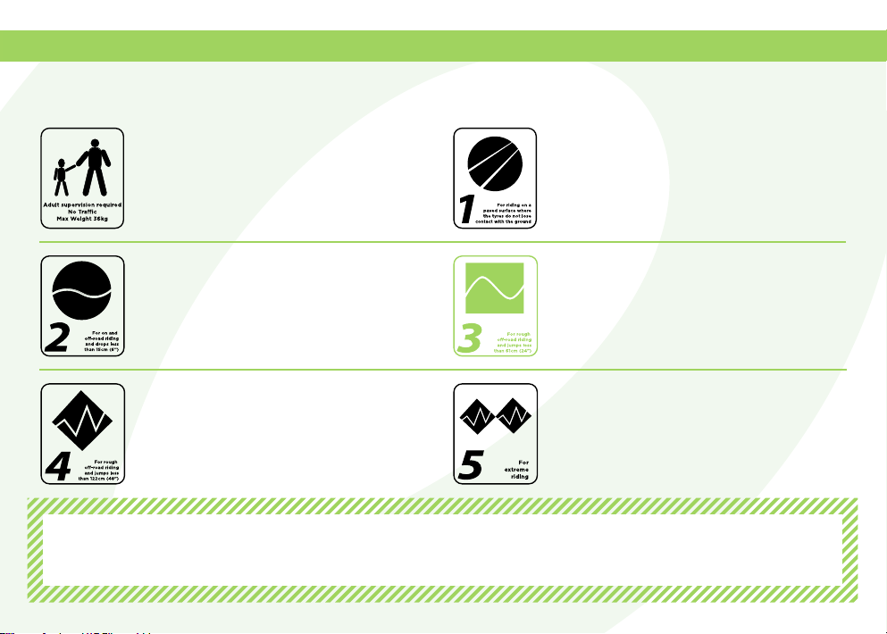
Intended Use: Condition 3
This is a set of conditions for the operation of
a children’s bicycle under appropriate parental
supervision in a manner consistent with the
child’s bicycling skills.
This is a set of conditions for the operation of
a bicycle on a regular paved surface where the
tires are intended to maintain ground contact.
This is a set of conditions for the operation of
a bicycle that includes Condition 1 as well as
unpaved and gravel roads and trails with mod-
erate grades. In this set of conditions, contact
with irregular terrain and loss of tire contact
with the ground may occur. Drops are intended
to be limited to 15cm (6”) or less
This is a set of conditions for operation of a
bicycle that includes Condition 1 and Condition
2 as well as rough trails, rough unpaved roads,
and rough terrain and unimproved trails that
require technical skills. Jumps and drops are
intended to be less than 61cm (24”).
This is a set of conditions for operation of a
bicycle that includes Conditions 1, 2, and 3, or
downhill grades on rough trails at speeds less
than 40km/h (25 mph), or both. Jumps are
intended to be less than 122cm (48”).
This is a set of conditions for operation of a
bicycle that includes Conditions 1, 2, 3, and 4;
extreme jumping; or downhill grades on rough
trails at speeds in excess of 40km/h (25 mph);
or a combination thereof.
Although we test our bikes beyond their intended usage and weight, the maximum safe combined weight for rider + luggage
is as follows: Hellion X20: 40kg Hellion X24: 50kg
Note: The bike is NOT suitable for the fitting of a luggage carrier, child seat or bicycle trailer.
It is not recommended to to fit stabilisers to the bike

8
1Lift the folded tabs from the box. Be careful not to damage
the bike box. It can be used again. 2Lift the seatpost assembly and wheels out of the box.
Keep these in a safe place.
3Lift the bike upwards and out of the box. 4Rest the bike on the ground either leaning up against the
box or standing safely.
UNBOXING HELLION X24

9
1Lift the folded tabs from the box. Be careful not to damage
the bike box. It can be used again. 2Lift the seat post assembly out of the box. Keep this in a
safe place.
3Lift the bike upwards and out of the box.
UNBOXING HELLION X20

10
1Remove protection from stem and remove the protective
wrapping from the handlebar. Remove the stem bolts using
the 4mm allen key and put them somewhere safe. 2Mount the handlebar to the stem and install the faceplate.
4Make sure the gaps of the stem are even, and that the
logos are centrally aligned. Torque bolts to 5-6Nm.3Tighten the screws in the order above 1 - 4 to achieve
even clamping.
HANDLEBAR ASSEMBLY

11
1Remove the saddle and seatpost assembly from the pack-
aging. Loosen the seat clamp by opening the quick release
(QR) lever and insert the seatpost.
3Tighten the QR clamp by closing the lever.
2It is important the seat post is always inserted past the
minimum insertion mark on the seatpost.
SEATPOST MINIMUM INSERTION AND HEIGHT ADJUSTMENT

12
REAR DERAILLEUR ASSEMBLY
1Carefully cut the cable ties holding the mech to the frame
and remove the bubble wrap and foam packaging. 2Using the 5mm allen key, Fit the derailleur into the mech
hanger but do not tighten yet.
3Before tightening the derailleur bolt, make sure the notch
on the derailleur sits behind the tab on the mech hanger. 4Tighten the derailleur bolt to 8-10Nm, use a torque
wrench if you have one.

13
REAR WHEEL ASSEMBLY (HX24)
1Remove the protective
packaging from the rear
wheel. 3Install the rear wheel into the dropouts plates on the
frame. Make sure the chain wraps around the cassette.
To make this easier pull the rear mech towards the back of
the bike.
4Install the rear axle into the frame - be careful on the first
couple of turns to ensure the axle engages with the
thread. Tighten the axle by turning it clockwise by hand
to 10-15Nm.
5You can re locate the position of the rear axle lever by
pulling the lever out.
2Remove the rear axle
from the frame and
remove the rear wheel
axle location box.

14
FRONT WHEEL ASSEMBLY (HX20)
1Remove the packaging from the front fork and the front
wheel. Be careful not to lose the hub end caps.
3Remove the brake pad spacer, and Insert the front wheel
into the fork dropouts making sure the rotor is centered in
the brake calliper and the axle hole is lined up. 4Slide the 15mm axle into the fork from the left hand side
(disc side), gently turn the axle to engage the first few
threads, then tighten to 12-15Nm. Once tight, check the
disc brake operates correctly.
2Using the 5mm allen Key, unscrew the axle and remove
from the fork.

15
3Remove the brake pad spacer, and Insert the front wheel
into the fork dropouts making sure the rotor is centered in
the brake calliper and the axle hole is lined up. 4Slide the 15mm axle into the fork, then gently turn the
axle to engage the first few threads and tighten to the
fixed position, tighten the QR axle to 15Nm by pressing
the lever. Check the disc brake operates correctly.
2Open the axle quick release (QR) lever, unscrew the axle
and remove from the fork.
FRONT WHEEL ASSEMBLY (HX24)
1Remove the packaging from the front fork and the front
wheel. Be careful not to lose the hub end caps.

16
CHAIN GUARD INSTALLATION (X20)
2Remove the crank preload bolt. Then remove the non
drive-side crank arm.1Using the supplied 5mm allen key. Remove the 2 pinch
bolts.
4Install the guard plate using the 2 x M6 bolts - don’t fully
tighten, make sure the plate can still be rotated.3You now should be able to remove the drive side crank
assembly.

17
5Reinstall the drive-side crankset, install the chain guard
cover, and install the 2 x M5 bolts and tighten to 3Nm. 6Once installed cycle the suspension to make sure the
chain doesn’t contact the chainguard.
7Rotate the cranks to gain access to the 2 x M6 bolts and
tighten to 6Nm. 8Reverse the instructions above to re install the non drive-
side crank arm, tighten the preload bolt to 0.7 - 1.5Nm,
and tighten the pinch bolts to 12Nm.

18
PARTS KIT
A1 X RIGHT ANGLED 22.2MM BRACKET
B1 X STRAIGHT BRACKET
CHEADSET BOLT INSERT
D1 X RED REAR REFLECTOR
E1 X WHITE FRONT REFLECTOR
F2 X WHEEL REFLECTORS
TOOLS REQUIRED
Crosshead screw driver
1
2
PEDAL ASSEMBLY
Make sure you take note of which pedal is the right hand
pedal, and which is the left hand pedal. Apply some grease
to the threads. If there are washers supplied in the parts
kit, make sure to use them.
Using the 6mm allen key provided, tighten the pedal to
35Nm. The drive-side pedal is tightened clockwise, the non
drive-side pedal is tightened anti-clockwise.

19
2Remove the split screw from the bracket and fit to the han-
dlebar by slotting the handlebar between the split in
the bracket. Re install the screw and nut and tighten to 3Nm.
1To fit the reflectors. Locate the 22.2mm right angled
bracket and white reflector. Slide the reflector down on to
the bracket until the it “clicks” into position.
FRONT REFLECTOR
2Remove the split screw from the bracket and fit to the
seatpost by slotting the post between the split in the
bracket. Re install the screw and nut and tighten to 3Nm.
REAR REFLECTOR
1Locate the appropriate bracket. Slide the red reflector
down onto the bracket until the reflector “clicks”
into position.

20
1
WHEEL REFLECTOR
Your bike will be supplied with 2 x wheel reflectors. These can be installed on either side of the bike. There is one for each wheel
PARTS KIT continued
To install, slot the wheel reflector between 2 spokes com-
ing from the same side of the hub e.g. drive-side or non
drive-side. 2Slide the reflector towards the centre of the wheel until
you feel the it locates with a soft “click”into position.
To fit the headset bolt insert - push the insert by hand into the
headset bolt. The insert will help stop water/mud from settling
inside the bolt and protect it from corrosion.
HEADSET BOLT INSERT BELL
Some bikes are supplied with a bell. To install the bell, remove
the bolt using the crosshead screwdriver. Slot the handlebar
between the split in the bell and re tighten the bolt to 3Nm.
This manual suits for next models
1
Table of contents
Other EARLY RIDER Bicycle manuals