EAST PENN Deka Ready Power Lithium User manual

LITHIUM BATTERY SERVICE MANUAL
Supporting All Generation One Lithium Batteries

22
Introduction.......................................................3
Training ..................................................................... 3
How to Use This Manual.......................................... 3
Safety .................................................................3
General ..................................................................... 3
Elements of Concern ............................................... 3
Proper PPE, Tool, and Equipment........................... 3
Electrolyte Exposure ................................................ 4
Service ...............................................................4
Overview.................................................................. .4
Tools & Equipment Required ................................... 4
Quick Reference Torque Values .............................. 4
External Components & Accessories - Removal /
Replacement ............................................................ 6
Internal Components Replacement........................ .8
Troubleshooting..............................................11
Overview..................................................................11
Troubleshooting Methodology................................11
Troubleshooting Chart ............................................11
Pack Advisor Service Tool ......................................14
Specic Troubleshooting Tasks..............................15
Appendix..........................................................18
TABLE OF CONTENTS

3
1: INTRODUCTION
1:1 Training
This manual is meant to assist with Deka Ready Power troubleshooting
and service. All topics covered in the following sections are taught
in the Deka University DRP Technician class. It is recommended
that DRP technicians participate in this class to receive a complete
understanding of DRP operation, troubleshooting, and service
of lithium batteries and their approved chargers. Work with you
branch management to enroll in an upcoming class.
1.2 How to Use This Manual
For easier navigation, the digital version of this manual contains links
to each section in the table of contents on page 2. Use these to quickly
navigate to the desired section.
The symbols below are used throughout this manual to indicate
important information.
NOTE: Indicates information that may affect product performance or
actions that would void the product warranty.
CAUTION: Indicates information that involves operator safety or
potential product damage.
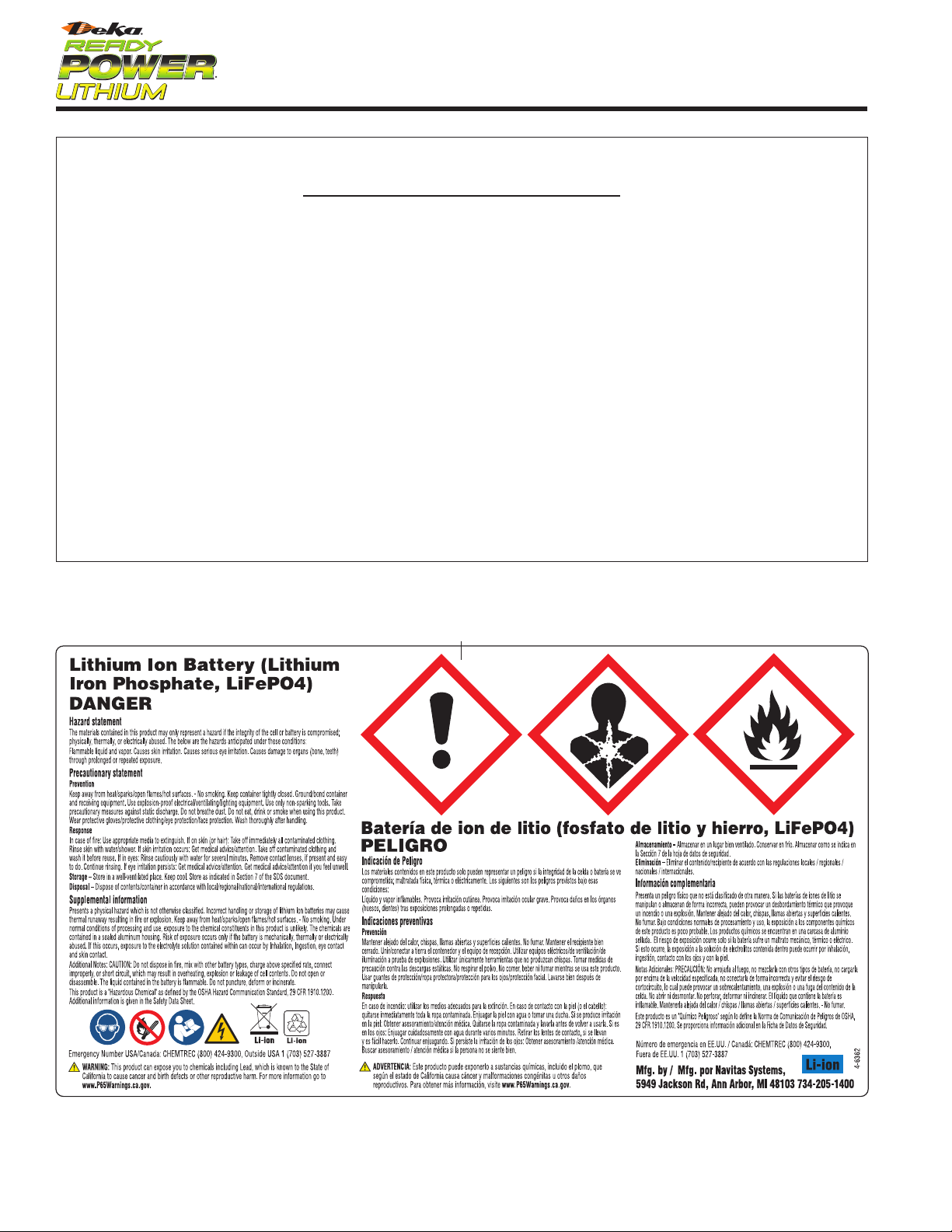
2: SAFETY
2.1 General
When used properly, the Deka Ready Power Li-ion motive power
battery is a safe, dependable source of electrical power. However, the
materials contained within this product may present a hazard or haz-
ardous condition if the integrity of the cell or battery is compromised.
Only trained and QUALIFIED personnel should install, use, or service
this equipment.
Consult the Safety Data Sheet (SDS) for additional precautions and first
aid measures. The SDS can be obtained at www.dekareadypower.com
2.2 Elements of Concern
There are five main potential hazards when not used and maintained
as designed in a Deka Ready Power Li-ion battery: electrolyte,
off-gassing, arc flash and shock potential, and weight.
1.
Electrolyte:
The electrolyte in a Li-ion battery plays a key role in
transporting the positive lithium ions between the cathode and anode.
The most common electrolyte is comprised of lithium salt, such as
LiPF6 (an organic solvent), containing ethylene carbonate, dimethyl
carbonate, and diethyl carbonate. Electrolyte can be a safety hazard
since it contains flammable solvents and if the Deka Ready Power
is damaged or incorrectly charged, it may lead to explosion and fire.
Electrolyte in the presence of water will also produce Hydrofluoric acid.
Consult SDS for additional precautions and first aid measures.
2.
Off-Gassing:
Cells have one time use pressure relief vents to allow
excessive pressure out. Excessive pressure is due to the breakdown
of the electrolyte. This breakdown may produce an “organic” smell
(similar to a permanent marker). Allow off-gassing to dissipate before
servicing a battery and contact the local Deka Representative for
further guidance.
3.
Electricity:
An electric shock hazard exists for persons who contact
live parts of batteries when the voltage is over 60 volts DC. The higher
the voltage, the greater the electric shock hazard. Do not touch battery
terminals while the Deka Ready Power is operating.
4.
Arc Flash:
The light and heat produced as part of an
arc fault
, a
type of electrical explosion or discharge that results from a connec-
tion through air to ground or another voltage phase in an electrical
system. Be sure to consult a hazard category classification table, like
that found in NFPA 70E. Table 130.7(C)(15)(a) lists a number of typical
electrical tasks by various voltage levels and recommends the category
of PPE that should be worn. The second method of selecting PPE is
to perform an arc flash hazard calculation to determine the available
incident arc energy. An industry manual from the Institute of Electrical
and Electronical Engineers (IEEE) labeled IEEE 1584 provides a guide
to perform calculations given the maximum fault current, duration
of faults, and other general equipment information is known. Once
the incident energy is calculated, the appropriate Personal Protective
Equipment (PPE) can be selected. Only personnel trained in NFPA 70E
and the Deka Ready Power should service the Deka Ready Power.
5.
Weight:
The average lift truck battery weighs more than 2,000 lbs.
(900kg). It can cause serious injury if it isn’t handled carefully during
installation, removal, and transport. Always use proper lifting equip-
ment and techniques.
2.3 Proper PPE, Tool, and Equipment
1.
Wearing Protective Clothing:
Technicians working on or near Deka
Ready Power batteries should always wear proper protective clothes
including safety glasses, gloves, and safety toed shoes. Remove all
metal jewelry to prevent an electric shock. Consult with the National
Electrical Code (NEC), National Fire Protection Association (NFPA)
NFPA 70E, and local codes when working with exposed and/or
energized electrical conductors.
2.
Lifting Batteries:
Always use the proper lifting equipment to reduce
the risk of tray damage, shorting and possible injury. An insulated
battery lifting beam of the proper weight capacity rating with an
overhead hoist is the safest way to move a battery. An insulated lifting
beam, with hooks that fit properly into the lifting ears in the tray, can
be used with almost any type of overhead hoist. Be sure the lifting
hooks align perfectly with the battery lifting ears. Misaligned hooks
can cause battery lifting ear damage and could disengage while the
battery is being lifted.
3.
Using the Battery as a Counterweight:
For most lift trucks to
operate safely, the battery is part of the counterweight system of the
forklift truck. The battery must be within the recommended battery
weight range specified on the forklift truck’s nameplate. The battery’s
service weight is noted on the ID label affixed to the battery counter-
weight (refer to section 5.8.2). A battery that is too heavy or too light
can change the truck’s center of gravity and cause it to be unstable.
It is the user’s responsibility to be sure the battery is within weight
specifications of the forklift truck.
4.
Charging Areas – Proper Equipment:
The Deka Ready Power
should be charged using only approved charging equipment in
designated charging areas.
5.
Fire Fighting Equipment:
Hand-operated fire extinguishers should
be available in all charging areas even if the areas are equipped with
automatic sprinkler systems. For information on extinguisher class,
size, and mounting locations, consult local fire authorities and your
insurance carrier.
6.
Disconnecting Charger:
Always press the “Stop” button on
the charger prior to disconnecting a battery that is being charged.
Not using the “Stop” button will damage the battery and charger
receptacles.
3

4
• Multimeter with voltage and continuity reading
• Windows based laptop
• PCAN Tool (Part Number 01-135-0008)
• PCAN Interface Harness (Part Number 03-920-0456)
3.3 Quick Reference Torque Values
Processes in the following service sections will call out the need to
torque hardware to proper spec. Use this section to quickly identify the
proper tool and torque values for all serviceable hardware. Match color
on the diagram to the corresponding color on the chart.
NOTE: Failure to follow the proper torque spec may result in immediate
damage to parts if over torqued or eventual loosening and battery
in-operation if under torqued.
NOTE: External terminal nuts, and internal busbar nuts both require
a 19mm wrench to install and remove, however they have a different
thread size and pitch. During service, be sure to use the proper nut to
prevent damage to threads or hardware seizing in place. Partial hand
thread these nuts before using tools to bring to final torque.
3.3.1 External Torque Values – All batteries (except 48v 1050ah)
Battery Lid
2.4 Electrolyte Exposure
If the Deka Ready Power battery pack case is crushed, damaged, or
compromised, inadvertent contact with the electrolyte may occur. This
can cause damage to eyes, skin, nose, throat, lungs, and respiratory
tract if inhaled. Be sure to review the SDS before handling.
1.
Electrolyte Spills:
Spills are unlikely as the battery is enclosed in a
steel case and the electrolyte is absorbed onto a substrate and cannot
flow under normal conditions. However, if the battery is crushed, or
compromised with a release of electrolyte, the electrolyte should be
contained and absorbed with suitable materials (e.g., sand and/or
vermiculite): the appropriate PPE shall be worn.
2.
Contact w/skin:
If any materials from inside the cell contact skin,
immediately wash exposed area with plenty of water for at least 15
minutes. Remove any contaminated clothing, jewelry etc. If Calgonate
is available, use as directed. Calgonate Gel is an effective topical 2.5%
calcium gluconate gel that is used in first aid response to hydrofluoric
acid (HF) exposure or contact to the body. Contact emergency services
if needed.
3.
Eyes:
If contact with eyes, rinse with water for several minutes.
Remove contact lenses, continue rinsing. Contact emergency services
if needed.
4.
Inhaled:
Remove person to fresh air and keep comfortable for
breathing. Contact emergency services if needed.
3: SERVICE
3.1 Overview
Maintenance of this product should only be performed by trained and
qualified individuals. Failing to follow set instructions may result in
personal injury or damage to the product.
Fully read and understand the process before conducting any trouble-
shooting or service on a Deka Ready Power lithium battery or accessory.
Contact a member of the Navitas service team if you have any questions
about any of the processes listed below.
Support@navitassys.com 734-205-1402
3.2 TOOLS & EQUIPMENT REQUIRED
Insulated tools are required when working on Deka Ready Power
batteries.
Below is a list of common tools needed to troubleshoot and service a
Deka Ready Power lithium battery:
• 19mm insulated socket
• 17mm insulated socket if working on a 48v 1050ah
• 13mm insulated socket
• 10mm insulated socket
• 8mm insulated socket
• 3/8” insulated socket
• 4mm hex key if working on a 48v 1050ah
• 3mm hex key if working on a 48v 1050ah
• 15mm open ended wrench
• Insulated socket extension
• Insulated socket driver
• Insulated screwdriver set
• Hex key set

5
3.3.2 Internal Torque Values – All Batteries (except 48v 1050ah)
2 Contractor Battery
3 Contractor Battery
24v Battery

6
3.3.3 Internal / External Torque Values – 48v 1050ah
3.4
External Components &
Accessories – Removal / Replacement
3.4.1 External Component Overview
48v 1050ah Battery

7
CAUTION:
DO NOT
pull the connector by the wires as this may damage
the cable.
3. Remove the opposite end from the UIM by unscrewing the connector
retaining ring and pulling the connector away from the UIM box.
4. If the UIM is equipped with a truck communication cable, disconnect
the truck side end by pressing firmly on the single gray locking tab and
pulling away from the truck harness.
CAUTION:
Grasp both harnesses by their plastic connectors and not by the
wires, to prevent damage to either harness.
5. Remove the truck communication cable from the UIM by unscrewing
the connector retaining ring and pulling the connector away from the
UIM box.
Reinstallation of the User Interface Module:
1. Follow removal steps in reverse.
2. Line up the 12-pin connector with the receptacle on battery lid so that
the alignment ‘keys’ match.
CAUTION:
Forcing the connector into the receptacle incorrectly can cause
damage to the battery and/or accessory. Always ensure proper alignment
‘key’ orientation before seating connector into receptacle.
3. Listen for clicks from the connectors, signifying the tabs have been
fully seated.
3.4.4 Battery Cables & Connectors (Charge
Cables)
The battery charge cable is used to connect with compatible chargers
and can be used to power fork trucks with a compatible connector or
jumper cable. The battery charge should be inspected frequently and
replaced when signs of wear or damage are present.
Removal of the Battery Cables:
1. Ensure the battery is powered off. Verify by measuring for voltage at
the cable ends. No voltage should be read.
2. If applicable, uninstall charge cable connector(s) from counterweight
lid.
3. Remove counterweight lid.
4. Disconnect the data cable connector from the battery. This may be
connected to the BMID, an accessory harness, or directly into the
receptacles on the battery lid.
5. Remove battery terminal covers. If they are the metal style, be careful
not to drop any hardware into battery lid holes exposed when cover
is removed.
6. Remove terminal nuts holding down the cable needing to be replaced.
DO NOT
allow nuts to fall into contactor nut access hole.
7. Remove battery cable from terminal posts.
8. If the battery is to remain in this state for an extended time, reinstall
terminal covers to prevent foreign objects from entering the battery
through the exposed access holes. This only applies to batteries using
metal terminal covers.
3.4.2 Counterweight Lid
The battery’s counterweight may have been shipped with a lid to protect
the external cables from damage. This lid will need to be removed to
allow for maintenance on the cables or internal parts.
Removal of the counterweight lid:
1. Ensure the battery is powered off.
2. Remove mounting hardware located on each of the corners of the
counterweight (example picture below).
3. If the counterweight has DC connector(s) and/or a Battery Discharge
indicator (BDI) mounted to the lid, you may choose to remove these
before lifting the counterweight lid off. This will make the lid lighter and
prevent damaging cables.
4. Lift the lid from the counterweight, being careful not to snag any of the
external cables with the lid mounting hardware.
Reinstallation of counterweight lid:
1. Visually inspect that all cables are routed in such a way as to not
interfere with the lid reattachment.
2. Set lid back onto counterweight. Be sure to align the swinging access
door over top of the battery communications receptacles.
3. Reinstall lid mounting hardware and tighten snug. There is no need to
over-tighten hardware
4. If applicable, re-install DC cable connector(s) and/or BDI to counter-
weight lid. Ensure and original spacers for DC connectors are rein-
stalled between counterweight lid and connector to allow for proper
charger connection.
3.4.3 User Interface Module (UIM)
Removal of the User Interface Module:
1. Ensure the battery is powered off.
2. Disconnect the battery communication cable from the CAN 1 recep-
tacle on the battery lid. Grasping the black connector by the narrow
ends, press firmly on the locking tabs while pulling the connector away
from the lid.

8
3.4.7 Battery Monitor Identification (BMID)
Harness
The BMID cable is used to aid in the communication between the
battery and charger.
Removal of BMID harness:
1. Ensure the battery is turned off.
2. Grasp the gray connector by the narrow ends, press firmly on the tabs
while pulling away from the battery lid.
DO NOT
pull connector by the
wires. This will cause cable damage and may result in the product not
working as expected.
3. Repeat process for opposite end of the cable.
Reinstallation of BMID harness:
1. Follow removal steps in reverse.
2. Listen for clicks from the connectors, signifying the tabs have been
fully seated. Loose connections can cause intermittent communication
issues and cause the battery to fault or affect the ability to charge
properly.
3.5 Internal Components Replacement
3.5.1 Internal Components Overview
Reinstallation of the Battery Cables:
1. Follow removal instructions in reverse.
2. Torque all terminal nuts to spec.
3. Reinstall all terminal covers and torque hardware to spec. (if using
metal covers).
4. Reconnect the data cable connector to battery how it was previously.
Ensure all alignment ‘keys’ are oriented correctly, and connectors
are fully seated. Loose or incorrect connection may prevent proper
charging.
5. If applicable, reinstall cable connector(s) to counterweight lid. Be sure
to use any connector spacers that were originally supplied.
6. Reattach the counterweight lid.
3.4.5 Battery Cables Other Than Charge
Cables (Truck Power)
Your application may use a SB, A320 or SBX cable for dedicated truck
power. These cables are similar to charge cables with the exceptions
that they are rarely mounted to the counterweight and have no data
cables to connect to the battery.
Removal of the Battery Cables:
Follow the steps outlined in above in “Battery Cables & Connectors
(Charge Cables) Removal”, with the exceptions that you won’t have a
counterweight bracket or data cable to remove.
Installation of the Battery Cables:
Follow “Battery Cables & Connectors (Charge Cables) Install”.
Disregard the data cable and counterweight bracket installation.
3.4.6 Battery Monitor Identification (BMID)
The BMID is used to aid in the communication between the battery and
charger. Note that this is only on 1.0 and 1.25 BMS batteries, and 1.4 do
not require them since they have an integrated BMID within the BMS.
Removal of the BMID:
1. Ensure the battery is turned off.
2. Disconnect the two communication cables connected to the BMID by
firmly pressing in on the tabs and pulling the connectors away from the
module.
DO NOT
pull by the wires or damage may occur.
3. Remove the two screws holding the module to the battery lid.
Installation of the BMID:
1. Follow removal steps in reverse.
2. Install and torque the mounting screws to spec.
DO NOT
overtighten
or damage to threads may occur.

9
Installation of the new fuse:
1. Follow removal steps in reverse.
2. Install fuse over the two exposed studs.
3. Reattach the sensor on the stud closest to the contactor.
4. Install the 2 nuts attaching the fuse to the tray and torque to spec.
5. Reinstall the fuse access door and screws and torque to spec.
6. Reinstall counterweight lid if applicable.
3.5.3 Battery Lid
Removal of the battery lid will allow access to the fuse (if not equipped
with a fuse access door), battery management system (BMS), contactors
and communication harness. NFPA70E personal protection equipment
will be worn during this work.
CAUTION: All components below the battery lid should be considered
live and care should be taken to prevent bodily injury or product damage
due to electrical arcing.
NOTE: External terminal nuts, and internal busbar nuts both require
a 19mm wrench to install and remove, however they have a different
thread size and pitch. During service, be sure to use the proper nut to
prevent damage to threads or hardware seizing in place. Partial hand
thread these nuts before using tools to bring to final torque.
Removal of the battery lid:
1. Ensure the battery is turned off.
2. Remove counterweight lid if applicable.
3. Remove all battery power cables.
4. Disconnect the portion of the BMID cable that is connected to the CAN
2 receptacle on the battery lid.
5. Remove the 2 flexible busbar nuts within the battery through the
access holes on the lid. Carefully use an insulated magnetic tool or
your finger to pull the nuts out of the access holes.
6. Remove the 4 bolts that secure the two CAN connectors (Gray & Black)
to the battery lid. Allow the connectors to fall inside the battery.
7. Remove the bolts around the perimeter of the battery lid.
8. Cut the warranty seals located on edges of the battery lid.
9. Remove the battery lid by first lifting straight up then away to clear the
flexible busbars on the contactor studs.
NOTE: Do not leave the battery in this state unattended. Reinstall the
lid or put a nonconductive cover over the top to prevent arcing risk
from foreign objects falling into the battery before leaving.
Installation of the battery lid:
1. Reinstall the lid by first ensure proper alignment of the fuse access
door on the battery lid over the fuse area inside the battery.
2. Lower the narrow side of the lid closest to the positive terminals first
and allow it to rest on the battery case while continuing to hold the
opposite side up.
3. While holding the opposite side of the lid up, place the gray CAN
communication receptacle into the far hole in the lid making sure
the keyed slots are away from the positive terminal. Use the two of
the shorter M6 screws and finger tighten them to hold the connector
in place.
4. Install the black CAN receptacle into the other hole in the lid. Install
the remaining 2 short M6 screws, finger tight, to hold the connector in
place to the battery lid.
3.5.2 Fuse
The Deka Ready Power Battery is current protected by an internal fuse.
On most battery models, the fuse is accessible through the fuse access
door on top of the battery lid. For models not equipped with the access
door, follow battery lid removal instructions to gain access to the fuse.
Depending on battery model, one of two types of fuses (barrel or flat)
will be utilized. Both fuse types are installed similarly and employ fuse
spacers to secure the assembly. See pictures below for examples of
each fuse type.
Removal of the fuse:
1. Ensure the battery is turned off.
2. Remove counterweight lid if applicable.
3. Remove the 4 fuse access door screws.
4. Remove the fuse access door.
DO NOT
drop hardware down the
exposed fuse access hole.
CAUTION:
This portion of the battery is always live. Take care when
working or reaching into the battery.
5. Remove the 2 nuts holding the fuse in place. Take note of the location
and routing of the sensor located on top of the contactor side of the
fuse.
6. Pull the sensor off the stud and set it aside for easy access later.
7. Remove the fuse

10
Installation of BMS:
1. Follow removal steps in reverse
2. Install BMS onto the mounting studs. On batteries equipped with a
triangular negative busbar, lift the busbar up while installing the BMS.
3. Install the BMS retention nuts and torque to spec.
4. Install the 3 busbar retention bolts onto the triangular negative busbar
(if equipped)
5. Install all flange nuts used to mount busbars to the BMS. Torque
to spec.
CAUTION: You must connect the comm. harness connector before
connecting the sense harness connector to the BMS. Failure to do so
may result in damage to the BMS
6. Reattach the comm harness connector to the BMS by setting it into
its receptacle and then swinging the latch handle back until the
connector is fully seated. Slide the red locking tab back to prevent
accidental disconnection of the connector.
7. Repeat the above step for the sense harness connector.
8. Use a cable tie to restrain the comm harness to the BMS. DO NOT over
tighten the cable tie or you may damage the wires.
9. Reinstall the battery lid, cables, and counterweight lid.
NOTE: Installing a new BMS may require installing new software before
the battery will function correctly. Reference the PACK ADVISOR User
Manual on how to perform this task.
3.5.5 Communication (Comm) Harness
The comm harness is responsible for collecting information from
the battery and delivering it to the BMS. It’s also part of the path
for exterior accessories and chargers to communicate to the BMS.
Disruption to this communication path may result in the battery not
functioning correctly.
Removal of Communication harness:
1. Remove the counterweight lid, battery cables, and the battery lid per
sections to gain access to the comm harness.
CAUTION:
All components below the battery lid should be considered live
and care should be taken to prevent bodily injury or product damage due
to electrical arcing.
2. Disconnect the sense harness connector from the BMS. To do this,
first slide the red locking tab forward. Then, while pressing on the
black locking tab, lift the black retention handle and swing it all the
way forward. It is now safe to pull the connector away from the BMS.
CAUTION: Before removing the comm harness, you must first
disconnect the sense harness connector from the BMS.
3. Disconnect and remove the comm harness connector from the BMS in
the same way the sense harness was done in the step above. Cut the
cable tie holding the comm harness to the BMS (if installed).
4. Remove the flange nut holding the SYS V1 ring terminal in place on
the fuse side of the positive contactor.
5. Remove the nut holding the Temperature Sensor ring terminal to
the fuse.
5. While continue to hold the lid up, route the loose communication
harness ring terminals up through the access holes in the lid. These
will be installed in a future step.
6. Slowly lower the lid while guiding the flexible busbar on to the con-
tactor stud. The positive side will go on first, followed by the negative
one. You may need to move the busbar with your finger, through the
access hole, to ensure proper alignment.
NOTE: Ensure wires going to the contactors have not been pinched
between the top of the contactor and the bottom of the battery lid.
7. Using your finger or an insulated tool, place the communication wire
ring terminals back over the contactor studs.
NOTE: Ring terminals must go on top of the flexible busbar, NOT
between the contactor and busbar.
8. Place 1 flange nut onto each contactor stud and hand thread but do
not fully tighten.
9. Reinstall all bolts around the perimeter of the lid. Torque to spec.
10. Torque the bolts holding the communication connectors to the
battery lid.
11. Torque the flexible busbar nuts to spec.
12. Apply 2 new warranty seals, 1 at each narrow end of the battery.
They should overlap the lip of the lid and onto the battery case.
13. Reattach battery cables, brackets, and terminal covers.
14. Reinstall the counterweight lid.
3.5.4 Battery Management System (BMS)
The BMS is a computer within the battery that monitors performance
and safety through signals sent by multiple sensors.
Removal of BMS:
1. Remove the counterweight lid, battery cables, and the battery to gain
access to the BMS.
CAUTION: All components below the battery lid should be considered
live and care should be taken to prevent bodily injury or product
damage due to electrical arcing.
2. Disconnect the sense harness connector from the BMS. To do this,
first slide the red locking tab forward. Then, while pressing on the
black locking tab, lift the black retention handle and swing it all the
way forward. It is now safe to pull the connector away from the BMS
and set out of the way.
CAUTION: You must remove the sense harness connector before
removing the communication harness connector. Failure to do so may
result in damage to the BMS
3. Remove the communication (comm) harness connector from the BMS
in the same way the sense harness was done in the step above.
4. Cut the cable tie holding the comm harness to the BMS.
5. Remove the 2 flange nuts securing the “L” busbar to the BMS and
negative contactor and the flange nut attaching the negative busbar to
the BMS.
6. On batteries with the triangular negative busbar, remove the three
bolts securing the busbar down to the tray below. DO NOT remove the
two nuts securing the triangular busbar to the vertical busbar in the
corner of the battery.
7. Remove the 4 BMS retaining nuts.
8. Remove the BMS by lifting the triangular busbar (if equipped) up
slightly and out of the way. Then lift the BMS up past the mounting
studs and out of the battery.

11
3.5.6 Contactors
Deka Ready Power batteries are equipped with two or more contactors
which are controlled by the BMS. Contactors open and close during
shutdown to prevent the flow of current to or from of the battery.
Removal of contactor(s):
1. Remove the counterweight lid, battery cables, and the battery lid to
gain access to the contactors.
CAUTION: All components below the battery lid should be considered
live and care should be taken to prevent bodily injury or product
damage due to electrical arcing.
2. Disconnect the contactor communication cable connector by pressing
in on the tabs located on each narrow end then lifting the connector up
and away from the contactor. DO NOT pull on the wires.
3. Remove any attached busbars or comm harness ring terminals by
removing the large flange nuts on each side of the contactor.
4. Remove the two contactor mounting nuts.
5. Pull the contactor up and off the mounting studs.
Installation of contactors:
1. Follow removal steps in reverse.
2. Install contactor over mounting studs. The communication receptacle
faces towards the outside of the battery case.
3. Install contactor mounting nuts and torque to spec.
4. Install busbars and comm harness ring terminals. Install and torque
large flange nuts to spec.
5. Install contactor communication connection into the corresponding
receptacle. The connector is keyed to only fit in one direction.
6. Reinstall the battery lid, cables, and counterweight lid.
4: TROUBLESHOOTING
4.1 Overview
This section covers the processes, tools and methodologies to suc-
cessfully troubleshoot the Deka Ready Power battery. Once the prob-
lem area has been pinpointed, reference the Service section of this
manual for direction on removal and replacement of the needed parts.
4.2 Troubleshooting Methodology
When troubleshooting a problem within a fork truck system, it is best
to start by narrowing down which section of the system is causing the
issue. Depending on the symptoms, this may require conducting tests
to isolate the truck from the battery, or the battery from the charger.
Once the faulty section has been isolated, further testing can pinpoint
the exact part needing to be repaired or replaced.
The Deka Ready Power battery product line is equipped with an
onboard Battery Management System (BMS), which will perform
self-diagnostics throughout operation. When the BMS detects a
failure, it will generate Diagnostic Trouble Codes (DTC’s) to assist
with troubleshooting efforts. Use the separate document “DTC
Troubleshooting Guide” to review a library of DTCs, their meanings,
and troubleshooting tasks to follow for each code.
6. Disconnect the contactor control cables by squeezing the tabs on
either narrow end of the connector and lifting it up and away from the
contactor. Make note of which connector goes to each contactor for
reinstallation purposes.
Installation of Communication harness:
1. Follow removal steps in reverse.
2. Install the Temperature Sensor ring terminal to the fuse and torque to
spec.
3. Install the flange nut holding the SYS V1 ring terminal in place on the
fuse side of the positive contactor bus and torque to spec.
4. Install the contactor connectors onto the proper contactor. They are
keyed to only fit in one direction.
5. Reattach the comm harness connector to the BMS by setting it into
its receptacle and then swinging the latch handle back until the
connector is fully seated. Slide the red locking tab back to prevent
accidental disconnection of the connector.
6. Install the sense harness to the BMS the same way the comm harness
was in the step above.
7. Use a cable tie to restrain the harness to the BMS. DO NOT over
tighten the cable tie or you may damage the wires.
8. Reinstall the battery lid, cables, and counterweight lid.

12
4.3 Troubleshooting Chart
Battery Will Not Power On
UIM/BDI Cable Disconnected or Damaged
1. Inspect/Reinstall/Replace cable.
2. Swap cable with Known good cable to test.
UIM/BDI Damaged/Not functional
1. Inspect/Replace Unit.
2. Isolate the UIM/BDI by jumping the wake pins on CAN 1 with a jumper across pins 7&8.
3. Swap UIM or BDI with a known good one to test.
Battery at low SOC (state of charge)
1. Check that the battery is able to connect to the charger.
2. If not/start troubleshooting why the charger and battery cannot connect in the next section of troubleshooting tips.
3. If it can connect, charge the battery.
HYG Cable Disconnected or Damaged
1. Inspect/Reinstall/Replace Cable.
2. Swap cable with a known functioning cable to compare
Active fault causing shutdowns
1. Connect with Pack Advisor and review the DTC’s (Diagnostic Trouble Codes) being generated to understand what could
be causing the shutdowns and follow up by testing and troubleshooting where the codes are generated from.
Crown Forklift Truck Variants
1. Verify the voltage transmitted from the truck harness for its’ safety feedback by verifying that the trouble codes do not
display an EWS_low, or EWS_hi fault.
2. Inspect/Repair/Replace feedback harness.
Battery Does Not Charge
Battery not communicating with charger
1. With a CAN enabled charger, verify that the Baud Rate matches what the baud rate of the battery. This is verified by
looking at the software and configuration settings to find out what the battery is set for, and the charger communica-
tions settings to make sure they are the same rate.
2. Try plugging the battery into a different charger.
3. With Pack Advisor, verify whether or not the battery sees the pilot from the charger by viewing if it switches to charge
mode when the charger is plugged into the battery.
4. Verify that the battery is configured correctly for that charger, and that both the software of the battery and charger are
the newest version or correct for the application.
5. Check the communications path between the Charger and Battery. IE: Charger cables, battery cables, BMID cable, and
communication harness.
6. Isolate the charger by jumping the wake lines on CAN 2, on top of the battery
Possible charger malfunction
1. Inspect charger/power cycle charger
2. If there is another battery there, see if the issue continues when you plug it into another unit.
3. Check charger for pilot voltage, and whether the CAN card is transmitting correctly.
Active Fault Causing Battery Shutdown
1. Review DTC’s and make corrective actions
BMS Unresponsive
1. Perform BMS reset
Battery Powers Off
When Not Commanded
Active fault causing shutdowns
1. Review the DTC’s being generated and make corrective actions
Communication path between truck and battery may be disconnected or damaged
1. Inspect/reinstall/replace battery to truck harnesses
2. If it is on the truck side, notify truck dealer so they can dispatch a technician to repair.
Erroneous sensor errors causing battery shutdown
1. Using Pack Advisor, view the voltages and temperatures in the data tables for a rapid rise or drop.
2. Use Pack Advisor to take a data log recording, to send to Navitas field service for evaluation.
3. If possible, connect the battery to a different truck, to isolate if it is the truck itself causing the issues.

13
4.3 Troubleshooting Chart continued
Truck Will Not Power On
Battery is powered off
1. Verify DC voltage at cable ends
2. Power Battery on through UIM/BDI, or CAN 1 cable
3. Refer to troubleshooting chart about battery won’t power on
Truck power cable disconnected/damaged
1. Inspect/reinstall/replace cables
Truck e-stop is engaged
1. Locate the e-stop and disengage it. This is a truck component/feature so the truck dealer might have to be present.
UIM/BDI Will Not Power On
UIM/BDI cable disconnected damaged
1. Inspect/reinstall/replace cable
Battery won’t power on
1. Refer to troubleshooting chart “Battery won’t power on”
UIM screen not functioning correctly
1. Verify whether or not the battery can power on by isolating it from the unit, and jumping the wake pins.
2. Test UIM on a different battery
3. Test the battery with a different UIM if able.

14
4.4.2 Pack Advisor Dashboard
The “Dashboard” is the default tab when you first start Pack Advisor
and gives basic information about the state of the battery. Reference
the “Pack Advisor User Manual” for more information about the
Dashboard and the other tabs in Pack Advisor. A brief description of a
few of the more useful parts of the Dashboard are below.
The “State of Charge” dial can help confirm if the battery has enough
charge to remain powered on and that it matches any other discharge
indicators equipped (UIM / BDI / integrated truck).
The “Current” dial shows the real time number of amps going in or out
of the battery as well as the limits the battery has set for both charge
and discharge current. Exceeding these limits may cause the battery to
shut down.
The “Operation Mode” dial indicates if the battery is ready to power
the fork truck, connected to a charger, or shutting down. This is useful
when diagnosing charging issues, as a failure to go into charger mode
when connected to a charger will indicate a potential communication
issue between battery and charger.
4.4.3 Viewing Diagnostic Trouble Codes (DTCs)
DTCs are available for viewing in the “Diagnostic Trouble Codes” tab
of Pack Advisor. Live or current codes as well as historical codes are
shown to aid in troubleshooting. Live codes are recorded as historical
once the battery has been power cycled. All codes are time stamped
using the batteries internal clock with both dates and times of when the
DTC was triggered. Use these timestamps to be sure you are reviewing
the more recent DTCs when beginning troubleshooting a new issue.
4.4 Pack Advisor Service Tool
Pack Advisor is a PC based service tool that when connected to a
Deka Ready Power battery, can provide performance, operation, and
diagnostic information. Pack Advisor also provides the ability to update
battery software and configuration.
The following sections will describe basic use of Pack Advisor to
assist in troubleshooting. For more detail on the installation and
full use of Pack Advisor, reference the separate “Pack Advisor User
Manual” document.
4.4.1 Connecting to the Battery
1. Open the counterweight access door (if equipped) to access the com-
munication receptacles on the battery lid.
2. Power down the battery. If the battery must remain powered on for
troubleshooting purposes, expect to see a DTC generated when con-
ducting the next step. This will not damage the battery but will be a
nuisance code.
3. Disconnect the CAN 2 (gray) connector from the receptacle on the
battery lid and install the PCAN harness into the CAN 2 receptacle. The
harness will be installed between the CAN 2 receptacle and the con-
nector that was just removed.
4. Power the battery on
5. Connect the PCAN harness to the PCAN dongle than connect the don-
gle to your PC via and available USB receptacle.
6. Open Pack Advisor, choose “PEAK-System Technik GmbH: PCANPT32”
and wait for the active signal to appear in the lower left corner. This
may only need to be selected the first time you open a new version of
Pack Advisor
7. Press scan at the lower right corner to connect to the battery.

15
4. Place a jumper between these pins, being carefully not to touch any
other pins.
5. If the battery is functioning properly, the contactors should close once
the short is made and maintained, turning the battery on. If the short
is removed, the battery will go into shutdown mode. The contactors
will open after an internal countdown. (Some configurations require the
short to be removed and then reapplied to shut the battery down).
4.5.2 Isolating the Charger Pilot Signal by
Jumping the CAN 2 Wake Line
Chargers with communication require a pilot signal to initiate the
charging operation. This signal is also used to wake the battery if it
was previously powered off. Follow the steps below if the battery is not
waking when connected to the charger to isolate the problem.
1. Ensure the battery is turned off at the user interface.
2. Locate the CAN 2 (gray) receptacle on the battery lid and remove the
connector if currently connected.
3. Using the figure as reference, identify pins 7 & 8 in the CAN 2
receptacle.
4. Place a jumper between these pins, being carefully not to touch any
other pins.
5. If the battery is functioning properly, the contactors will close once the
short is made and maintained, turning the battery on. If the short is
removed, the battery will go into shutdown mode. The contactors will
open after an internal countdown.
4.5.3 Troubleshooting Charger Communication
Path
The communication path from the charger to the Battery Management
System (BMS) is responsible for initiating the charging operation,
maintaining proper charge current and stopping the current at top of
charge. A break in this path may prevent any of these processes from
working properly.
The communication path consists of:
• Charger
• Charger Cable(s)
• Battery Cable(s)
Historical DTCs will only be available after pressing the scan button at
the bottom right corner of Pack Advisor. You will need to do this every
time a Pack Advisor is opened or connected to a new battery. The
green progress bar shows the state of the scan. Fully filled bar indi-
cates the scan is complete.
It is important when using the DTC list to focus in on the correct DTCs
and not older or less helpful codes. Below is an example of a DTC
list from a battery. When viewing the historical section, look for DTC
groups (highlighted in blue in this example). These are codes that all
occurred near the same time and would have caused a battery shut-
down. The codes at the beginning of this group are more useful than
those at the end.
To begin to diagnose the root cause, you must find the initial or first
DTC of the group. This is usually the most helpful code, as it will trigger
at the beginning of the fault and/or shutdown. Use the timestamps to
find the first code of the group (highlighted in red in this example). This
should be the first code used for troubleshooting.
Reference the “DTC Troubleshooting Guide” document for trouble-
shooting tasks for each DTC
4.5 Specific Troubleshooting Tasks
This section will expand upon the tasks called out in the
“Troubleshooting Chart” (in the sections above) and the separate docu-
ment, “DTC Troubleshooting Guide”. Use the following tasks along with
the instructions in the “Service” section to perform required testing
and validation tasks.
4.5.1 Isolating the User Interface by Jumping
the CAN 1 Wake Line
If a suspected fault with the user interface device (UIM or BDI)
is preventing the battery from powering on, it can be bypassed to
investigate.
1. Ensure the battery is not currently connected to a charger.
2. Locate the CAN 1 (black) receptacle on the battery lid and remove the
user interface connector if currently plugged in.
3. Using the figure as reference, identify pins 7 & 8 in the receptacle.

16
• BMID Y Harness (if equipped)
• BMID to CAN Harness (if equipped)
• Battery Monitor Identification Module (BMID)
• BMID Harness
• Communication Harness
• Battery Management System (BMS)
Using a multimeter and applicable schematic, check for correct pin lo-
cations and continuity between pins on any harnesses in question.
4.5.4 Resetting an Unresponsive BMS
If you find that the BMS won’t start when commanded and won’t com-
municate with user devices, the charger or the Pack Advisor service
tool, the BMS may be stuck in an idle state and need to be reset.
The only way to reset the BMS is by disconnecting the sense harness,
followed by the communication harnesses from the BMS, waiting 3
minutes and then reconnecting them.
1. Follow steps 1-3 in the BMS service section
2. Wait 3 minutes before reinstalling the connectors to the BMS.
3. The communication harness first, then the sense harness.
4. Connect to the BMS, turn the battery on, and test to verify BMS re-
sponds with no trouble codes.
5. Reassemble the lid and cabling on the top of the unit, and verify that
the battery will run the truck, and charge without issue.
4.5.5 Troubleshooting UIM Truck Cable
(CROWN)
Crown lift trucks require an extra cable from the User Interface Module
(UIM) to communicate with the truck. A break in this communication
path may cause battery shutdowns or truck error codes.
1. Use a multimeter and the applicable schematic to check for continuity
and pin location in this cable.
2. If you suspect the issue may be in the truck side harness, you can
isolate the UIM from the truck with a jumper. Place the jumper across
pins 4 & 5 on the gray 6 pin connector of the UIM-to-truck cable to
bypass the truck harness. If the battery remains on, then the problem
may be in the truck side harness.
4.5.6 Measuring Battery Voltage
It may be useful to measure the battery voltage without needing to
connect the Pack Advisor service tool. This could be used to verify the
battery hasn’t been overly discharged.
When contactors are closed (battery on):
Use a multimeter to measure for DC voltage between the positive and
negative terminals on the top of the battery lid. This is a good way to
tell if the contactors are closed when you expect them to be and may
help trouble shoot other issues.
3 contactor batteries may have 1 positive contactor open while the
other is closed. This is normal operation and may require checking for
voltage at each positive terminal.
When contactors are open (battery off):
On the CAN 1 (black) communication receptacle located on the battery
lid, measure across pins 7 & 8 to see battery voltage.
On the CAN 2 (gray) communication receptacle located on the battery
lid, measure across pins 7 & 8 to see battery voltage.

17
4.5.7 Verifying CAN Transmission Functionality
Verify proper CAN transmission out from the battery is helpful when
troubleshooting charging or integrated truck communication issues.
The first test requires the battery to be powered off, wile the second
requires the battery to be on.
When contactors are open – Battery is off:
Locate pins 1 & 12 on the CAN 1 (black) communication receptacle on
the battery lid. Set a multimeter to resistance and measure across pins
1 & 12. Proper operation should read roughly 120 ohms.
HYG Auto-Guided Vehicles (AGVs) may have a different resistance.
Check with your regional product support engineer for assistance.
For batteries equipped with a 1.4 version BMS, charging CAN com-
munication is transmitted through the CAN 2 (gray) communication
receptacle located on the battery lid. Set a multimeter to resistance
and measure across pins 1 & 12. Proper operation should read roughly
120 ohms.
When contactors are closed – Battery is on:
Locate pins 1 & 12 on the CAN 1 (black) communication receptacle on
the battery lid. Set a multimeter to DC voltage and measure across pins
1 &12. Now set the multimeter to AC voltage and remeasure. Proper
readings will be approximately 1.5 VDC, and .8 VAC.
For batteries equipped with a 1.4 version BMS, charging CAN commu-
nication is transmitted through the CAN 2 (gray) communication re-
ceptacle located on the battery lid. Set a multimeter to DC voltage and
measure across pins 1 &12. Now set the multimeter to AC voltage and
remeasure. Proper readings will be approximately 1.5 VDC, and .8 VAC.

18
5: APPENDIX
5.1 Supporting Documents
1. “Deka Ready Power User Manual”
2. “Pack Advisor User Manual”
3. “DTC Troubleshooting Guide”

19
Page Intentionally Blank

All data subject to change without notice. No part of this document may be copied or
reproduced, electronically or mechanically, without written permission from the company.
E.P.M. Form No. 2708 08/23 © 2023 by EPM Printed in U.S.A.
East Penn Manufacturing Co. Lyon Station, PA 19536-0147 Phone: 610-682-6361 Fax: 610-682-4781 www.dekabatteries.com
Table of contents
Other EAST PENN Batteries Pack manuals