Eastern Voltage Research Joule Thief 1.0 User manual

Joule Thief 1.0 Kit
May 2012, Rev 1 − 1 − http://www.EasternVoltageResearch.com
Joule Thief 1.0
J
Jo
ou
ul
le
e
T
Th
hi
ie
ef
f
1
1.
.0
0
K
Ki
it
t
(Please note that the image above represents our initial prototype devices. The device
you will receive when ordering will look somewhat different.)
I
In
ns
st
tr
ru
uc
ct
ti
io
on
n
M
Ma
an
nu
ua
al
l
E
Ea
as
st
te
er
rn
n
V
Vo
ol
lt
ta
ag
ge
e
R
Re
es
se
ea
ar
rc
ch
h,
,
L
LL
LC
C

Joule Thief 1.0 Kit
May 2012, Rev 1 − 2 − http://www.EasternVoltageResearch.com
Joule Thief 1.0
Introduction to the Joule Thief 1.0 Kit
Thank you for purchasing the Joule Thief 1.0. Our Joule Thief 1.0 kit has been one of
our most popular educational kits we originally offered only through the various outreach
programs we conducted here at Eastern Voltage Research. We recently decided to offer
this kit to the public and the feedback thus far has been extremely positive. So what is a
Joule Thief? Well, simply put, a Joule Thief is simply a circuit that utilizes the remaining
energy in an almost drained battery and uses that remaining energy to power some type
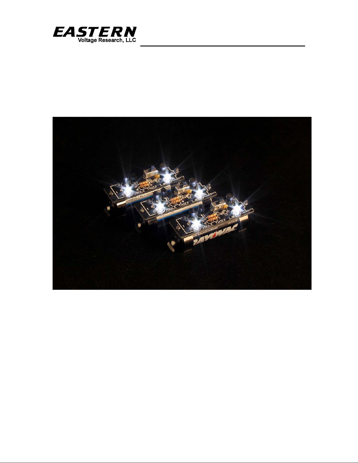
of electrical load or as in this case, two (2) LEDs. Its a fun way to use up all those "dead"
batteries you have lying around and put them to work in the form of a very bright LED
light source. The LEDs we utilize in our Joule Thief 1.0 kit are ultrabright white LEDs
which have a 110 degree viewing angle which is capable of illuminating an entire room if
its dark. A few of these can be extremely handy when the power goes out in your house
or on a camping trip. They are also very popular with the kids. Whenever I leave my
Joule Thief kits left unattended, my 4 year old son always manages to sneak and take
them away to play with them. They are so fun and the light they produce is spectacular!
Joule Thief circuits have been around for a very long time. There are many different
variations on the traditional Joule Thief theme, but they are all practically the same. The
Joule Thief 1.0 circuit is based on a conventional switching boost converter design, in
that it contains a single inductor and a switch, when operated, creates a higher voltage
than the input battery voltage. The classical Joule Thief circuit utilizes a custom wound
transformer with feedback winding, however, we have always felt this was a bit difficult
and tedious to wind, so decided to use a conventional boost circuit that uses an off-the-
shelf inductor instead of the transformer. In this particular case, the boost circuit converts
takes the energy from an AA or similar battery which can have an output voltage of
anywhere between 0.8V and 1.5V, and converts it to 6V to power two (2) white (or other
color) LEDs.
Notice to Beginners: If you are a first time kit builder, you may find this instruction
manual easier to understand than expected. Each component in this kit has an individual
check box, while a detailed description of each component is provided as well. If you
follow each step in the instruction manual in order, and practice good soldering and kit
building skills, the kit is next to fail-safe.
Please read this manual in its entirety before building, testing, or operating your kit!

Joule Thief 1.0 Kit
May 2012, Rev 1 − 3 − http://www.EasternVoltageResearch.com
Joule Thief 1.0
Circuit Description
The Joule Thief 1.0 kit is basically a simple boost converter power supply that converts
the low voltage of an AA battery (typically 0.8 to 1.5V) to a higher voltage of 6V to
power two (2) LEDs. Just as in classic boost converter, there is an inductor, L1, and a
switch, Q2. Energy is stored in the inductor during the ON period of switch, Q2, and
then the energy is released when the switch, Q1 is turned OFF. There are three (3)
primary switching cycles of operation which are described in more detail below:
SWITCHING CYCLE 1
Power is first applied to the circuit when switch, SW1, is closed. Current from the
battery, BAT1, flows through the 1k resistor into the base of Q2 turning Q2 ON. This
causes current to begin flowing from the battery through inductor, L1.
SWITCHING CYCLE 2
As current begins flowing through inductor, L1, this causes a voltage to begin charging
up across capacitor, C1, which eventually charges up sufficient enough at the base of Q1
to turn Q1 ON. C1 is charged directly from the battery through resistors R1 and R2.
Thus, the time constant of the switching is determined by the combined resistance of
R1+R2 and capacitance, C1. When Q1 turns ON, it pulls the base of Q2 to GND and
turns Q2 OFF. Once Q2 switches OFF, current stops flowing through inductor, L1.
Because the current in an inductor cannot stop instantaneously, the inductor induces a
large voltage across itself in an attempt to maintain current flow. This voltage (6V) is
created across the inductor to allow current to keep flowing through itself. The voltage,
is developed across LEDs, D1 and D2, and cause them to illuminate.
The oscilloscope plot below shows the voltage output of the Joule Thief which is across
the two (2) LEDs. The output voltage is 6.40V, which is the sum of the two (2) LEDs
forward voltages. The output current through the two (2) LEDs is approximately 50mA
peak at a duty cycle of 12%. The effective average output current being applied to the
LEDs is approximately 6mA (50mA * 0.12%) for this particular battery being used.

Joule Thief 1.0 Kit
May 2012, Rev 1 − 4 − http://www.EasternVoltageResearch.com
Joule Thief 1.0
LED Output Voltage and Current
(Yellow = Output Voltage 2V/div)
(Green = Output Current 20mA/div)
SWITCHING CYCLE 3
Once Q1 turns ON and Q2 turns OFF, C1 begins discharging its energy through current
limiting resistor, R3, and through the base of Q1. R3 is used to prevent the peak
discharge currents from C1 from overly stressing the base-emitter junction of Q1. Once
C1 discharges to a voltage less than 0.6V, Q1 turns OFF again and Q2 turns ON. This
switching process then repeats.
Finally, capacitor C2, resistor R4, and diode CR1 are utilized to provide soft turn-off /
turn-on functionality with your device. When the switch is turned ON, it takes a brief
amount of time to charge up capacitor C2 and this results in a pleasant looking soft turn-
on. The same is true for turn-off.

Joule Thief 1.0 Kit
May 2012, Rev 1 − 5 − http://www.EasternVoltageResearch.com
Joule Thief 1.0
Kit Building Tips
A good soldering technique is key! Let your soldering iron tip gently heat both the wires
and pads simultaneously. Apply solder to the wire and the pad when the pad is hot
enough to melt the solder. The finished joint should appear like a small shiny drop of
water on paper, somewhat soaked in. If the pads have not heated up sufficiently, melted
solder (heated only by the soldering iron itself) will form a cold solder joint and will not
conduct properly. These cold joints appear as dull beads of solder, and can be easily
fixed by applying additional heat to the pad and wire. All components, unless otherwise
noted, should be mounted on the top side of the board. This is the side with the
silkscreen printing.
When installing components, the component is placed flat to the board and the leads are
bent on the backside of the board to prevent the part from falling out before soldering.
The part is then soldered securely to the board, and the remaining lead length is clipped
off. It is also extremely important to place the components as close to the board as
possible. This is necessary for proper operation over the wide frequency range of the
various kits we provide. Also be sure that component lead lengths are always as short as
possible. This will avoid adding any stray capacitances or inductances that can be
detrimental to circuit operation.
An alternative approach (which is actually the one I use) is to install the component into
the board and then apply a piece of masking tape on the topside to the hold the
component in place temporarily. The leads on the backside of the board are then trimmed
leaving about 0.10” lead protruding through the backside of the board, and then soldered
from the backside. You can then remove the masking tape, and finally apply a small
amount of solder on the top to complete the joint on both sides. This is shown in the
figure below.

Joule Thief 1.0 Kit
May 2012, Rev 1 − 6 − http://www.EasternVoltageResearch.com
Joule Thief 1.0
Joule Thief 1.0 Kit Parts List
RESISTORS
1 1k Resistor (brown-black-red), R1
1 51k Resistor (green-brown-orange), R2
1 100 ohm Resistor (brown-black-brown), R3
1 330 ohm Resistor (orange-orange-black), R4
CAPACITORS
1 15pF Ceramic Capacitor (marked 15J), C1
1 22uF Electrolytic Capacitor, C2
DIODES
2 LED, White, T-1-3/4, D1,D2
SEMICONDUCTORS
2 2N3904 Transistor, Q1,Q2
1 1N4148 Resistor, R4
MISCELLANEOUS
1 Inductor, 330uH, L1
1 Switch, Slide, SW1
2 AA Battery Clips, BAT1
1 PCB Board, Joule Thief 1.0
1 Schematic, Joule Thief 1.0
REQUIRED, NOT SUPPLIED
1 AA Battery, BAT1

Joule Thief 1.0 Kit
May 2012, Rev 1 − 7 − http://www.EasternVoltageResearch.com
Joule Thief 1.0
Joule Thief 1.0 - Component Layout Diagram

Joule Thief 1.0 Kit
May 2012, Rev 1 − 8 − http://www.EasternVoltageResearch.com
Joule Thief 1.0
KIT Building Instructions
Now we will begin building the kit. There are just a few more important things to know
before we install the first components.
For each component, the word “install” always means the following:
1. Pick the correct value to start with.
2. Insert the component into the correct printed circuit board (PCB) location.
3. Orient the component correctly – especially when there is a right and a wrong
way to solder it in. (i.e. Electrolytic capacitors, diodes, ICs, transistors, etc…)
4. Solder all connections unless directed otherwise. Ensure enough heat is used to
allow solder to flow for clean, shiny, and completed connections.
Also, please be sure to take us seriously when we say that good soldering is the key to the
proper operation of your circuit!
Use a 25W soldering pencil with a clean, sharp tip. DO NOT USE a high power
soldering gun such as those trigger activated units.
Use only rosin core solder intended for electronics use
Ensure your work area is clean, and has plenty of bright lighting
Build your kit in stages, taking breaks to check your work. Be sure to clean the
board periodically with a brush or compressed air to remove any excess wire
cuttings, etc…
Okay, so lets begin!
1. Install R1, 1k resistor (brown-black-red)
2. Install R2, 51k resistor (green-brown-orange)
3. Install R3, 100 ohm resistor (brown-black-brown)
4. Install R4, 330 ohm resistor (orange-orange-brown)
5. Install CR1, 1N4148 diode (marking 1N4148)
6. Install C1, 15pF capacitor (marking 15J)
7. Install C2, 22uF electrolytic capacitor
8. Install L1, 330uH inductor (marking 331)

Joule Thief 1.0 Kit
May 2012, Rev 1 − 9 − http://www.EasternVoltageResearch.com
Joule Thief 1.0
9. Install D1, LED. The short lead of the diode is the cathode and will install into
the square pad on the PCB board.
10. Install D2, LED. The short lead of the diode is the cathode and will install
into the square pad on the PCB board.
11. Install Q1, 2N3904 transistor. This transistor needs to be orientated properly.
Please insert Q1 into the board with the flat edge of the transistor orientated
according to the silkscreen layout drawing.
12. Install Q2, 2N3904 transistor. This transistor needs to be orientated properly.
Please insert Q2 into the board with the flat edge of the transistor orientated
according to the silkscreen layout drawing.
13. Install SW1, switch. Note that there is no incorrect way to install this switch.
The switch may be inserted in any orientation.
14. Install the (2) AA battery clips to the underside of the board.
Congratulations! You have just completed your Joule Thief 1.0 kit. Please take a few
moments to look over the board and ensure that all the components are installed properly
with the correct orientation. Since some of the parts may be unfamiliar to you, you may
want to be extra sure that they have been inserted correctly. After you are sure that
everything seems to be properly installed, move on to the set-up and testing section.
Set-up and Testing
Okay, so lets begin!
1. Install an AA battery into the battery clips. Make sure the battery is installed
with the correct polarity.
2. Turn the switch to the ON position if the LEDs are not already illuminated.
Congratulations! Your Joule Thief 1.0 is now completed and operational.

Joule Thief 1.0 Kit
May 2012, Rev 1 − 10 − http://www.EasternVoltageResearch.com
Joule Thief 1.0
Troubleshooting
PROBLEM: The LEDs do not illuminate when I turn the switch ON.
SOLUTION: Verify that the LEDs are installed correctly, the battery is installed
correctly, and that the battery is not completely drained.
PROBLEM: The LEDs illuminate very dimly.
SOLUTION: The battery may be discharged below the 0.8V required for this circuit to
operate correctly.
Conclusion
We sincerely hope that you have enjoyed the construction of this Eastern Voltage
Research Kit. As always, we have tried to write this instruction manual in the easiest,
most “user friendly” format that is possible. As our customers, we value your opinions,
comments, and additions that you would like to see in future publications. Please submit
comments or ideas to:
Eastern Voltage Research, LLC
Technical Support
Thanks again from the people here at Eastern Voltage Research.
Terms and Conditions of Sale
Before opening or assemblying your kit, please read and review the latest Terms and
Conditions of Sale on our website at the following link:
http://www.easternvoltageresearch.com/terms.html
Table of contents
Popular Educational Equipment manuals by other brands

Regina
Regina FH-100E VER.2 instruction manual

Kyoto Kagaku
Kyoto Kagaku MW35 instruction manual

Bioloid
Bioloid STEM manual

FUTURE KIT
FUTURE KIT 617 quick start guide

Talk To Me Technologies
Talk To Me Technologies GoTalk NOW Plus wego A Series Quick reference guide

Sensotec
Sensotec my Board Buddy GO manual

Enabling Devices
Enabling Devices Switch & Glow user guide

Aircatglobal
Aircatglobal VirtualFly SOLO D4 user manual

Talk To Me Technologies
Talk To Me Technologies wego 13A-D quick reference

Festo
Festo EduTrainer 8108193 operating instructions

PASCO
PASCO ME-6989 instruction manual

Copernicus
Copernicus PTE78 Assembly guide