8FormC-1206
DESCRIPTION
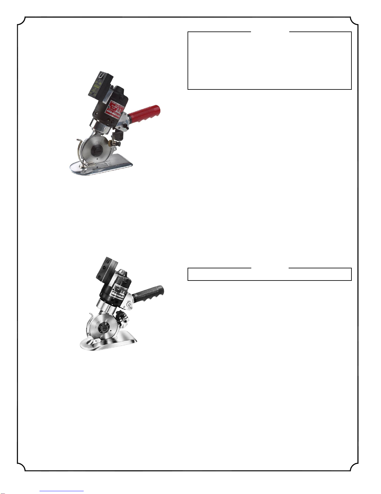
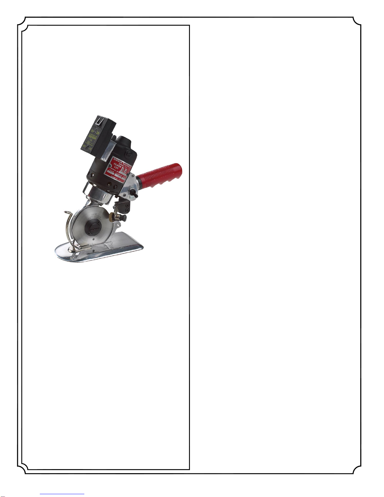
Your new Chickadee D2 or D2H is designed for increase perfor-
mance and capacity, with a minimum of maintenance and ser-
vice when not subjected to abnormal use.
CAUTION
Read instructions carefully before starting motor. Be sure
thatvoltageandcurrent are the same as stampedonname-
plate.
TO OPERATE MACHINE
Turn machine to on position; if cutter does not perform properly
check line output and be sure the unit it plugged in properly
making full contact. Do not attempt to start this unit while it is in
material to be cut.
WARNING
Before performing any of the following procedures, make
sure that the attachment plug has been disconnected from
power source.
REMOVE AND REPLACE THE KNIFE
Insert a pin thru knife against bottom of machine housing and
with a large screwdriver, remove screw (300C12-3) and flange
(53C11-112). DISCARD WORN SHARPKNIFE WITH CARE and
install new blade with the Eastman facing outward.
To obtain a fine keen edge on the blade, press lightly on sharp-
ener button with a constant pressure.
LUBRICATION
Follow this procedure yearly for intermittent use, or every six
months for continuous use. Remove knife, remove retainer plate
(79C12-276) (2 screws) with gear intact. Then remove screw
(20C13-99) emery wheel (541C1-24) and wipe away any grit de-
posits. Apply a light coat of Eastman Lubricko Grease (242C2-2)
to parts and reassemble. Then add small quantity of Eastman
Lubricko Grease to gears and shaft. Saturate wick (191C1-37)
with good quality SAE 30 non-detergent motor oil when
changing blade.
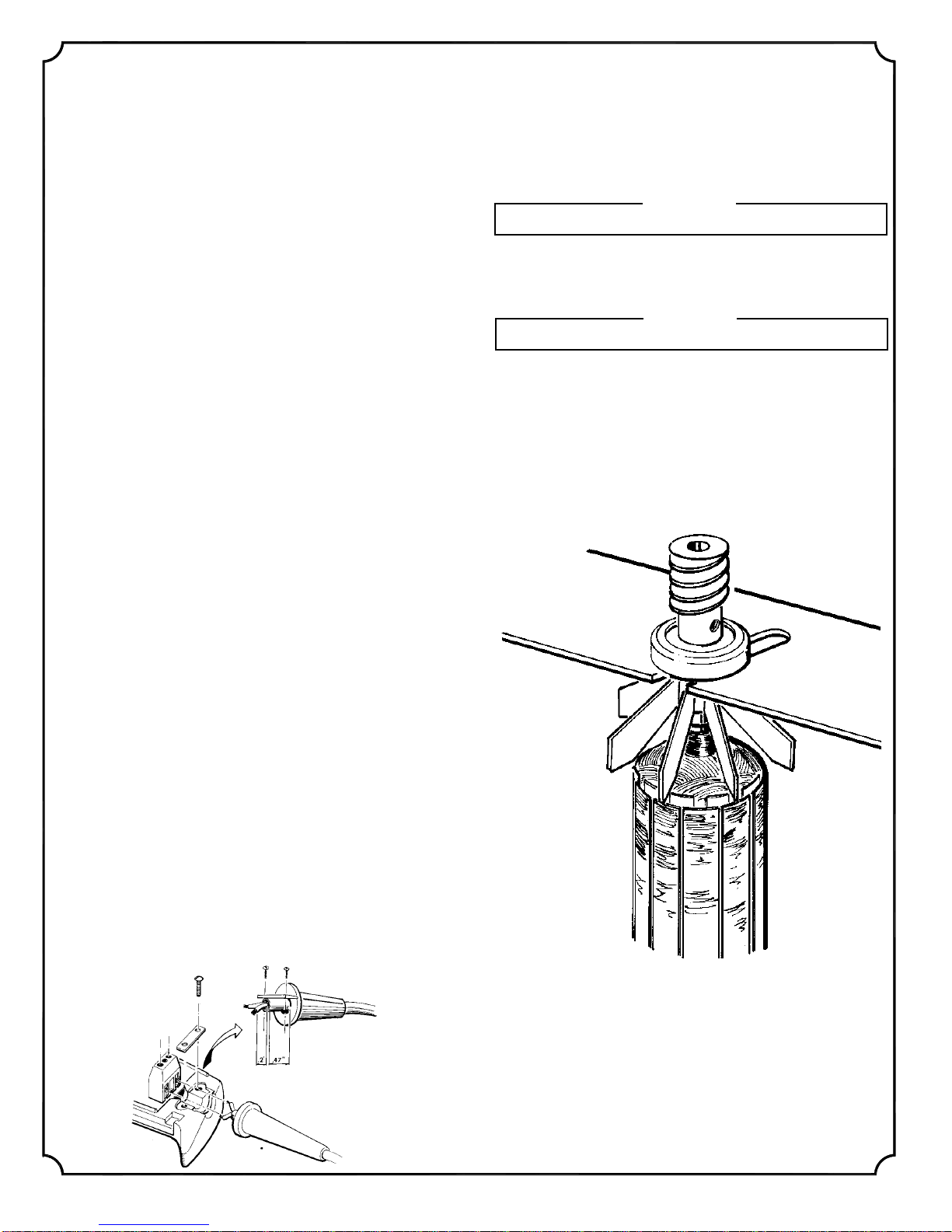
DISASSEMBLY
Remove knife. Remove two (2) flat head screws (302C8-2)
and gear retaining plate (79C12-276) from housing.
Note: it is not necessary to loosen two fillister head screws
(301C3-1) from knife flange.
Remove brush caps and brushes. Completely remove three
fillister head screws (308C1-1, 308C1-4, 308C1-5) from housing
and lift off left side motor housing, leaving motor parts in right
side housing. Clean lint and dirt from motor housing and grease
from gear cavity.
PART NO. DESCRIPTION
1C13-21 ............................................................................ SLEEVE
1C13-26 .................................................................CORD SLEEVE
4C1-149 ...........................................................................HEX NUT
4C2-106 ...........................................................................HEX NUT
10C1-45 ................................................................................... FAN
12C15-14 ....................................................... WASHER, FLAT #10
12C15-89 ........................................................................ WASHER
12C15-124 ...................................... WASHER, BLADE RETAINER
14C1-23 .................................................................. HANDLE GRIP
17C15-133 ............................................................ARMATURE PIN
17C15-136 ........................................... PIN LABEL (4 REQUIRED)
18C6-71 ...........................FRONT “O” RING HALF (2 REQUIRED)
18C6-72 ............................. BACK “O” RING HALF (2 REQUIRED)
20C13-99 ....................................................... PAN HEAD SCREW
21C6-3 ....................................................SHARPENER BUSHING
25C4-169 ................................................................ KNIFE GUARD
34C8-12 .............................................................................SPRING
34C10-165 ................................................. SHARPENER SPRING
50C7-25 ......................................................... CORD CLAMP D-2H
50C7-26 ............................................................CORD CLAMP D-2
52C5-176 ................................................................BASE SWITCH
53C11-112................................................KNIFE COVER FLANGE
57C1-61 ............................................................... SWITCH LEVER
63C3-22 .................................................... SHARPENER BUTTON
68C3-6 .............................................................PRESSURE FOOT
68C3-7 ........................................... NARROW PRESSURE FOOT
79C1-151 ........................................................... PLATE, NO. 120V
79C1-152 ........................................................... PLATE, NO. 230V
79C2-61 .............................................................. CAUTION PLATE
79C2-77 .................................................................... NAME PLATE
79C12-276 ............................................ GEAR RETAINING PLATE
79C12-284 ....... GEAR RETAINING PLATE FOR NARROW FOOT
80C1-147 .................................................... ROUND KNIFE, 2 1/4"
80C1-149 .......................................................... HEX KNIFE, 2 1/4"
83C4-25 ................................................................ KNIFE FLANGE
86C7-42 ............................................ BRUSH CAP (2 REQUIRED)
87C7-43 .....................................................................KNIFE GEAR
87C7-44 ................................................................... WORM GEAR
90C6-42 ............................................................... REAR BEARING
90C6-48 ............................................................. FRONT BEARING
95C5-7 ........................................................................ ALLEN KEY
98C4-32 .................................................................ON/OFF PLATE
109C5-1 ........................................................... TIP SHEAR PLATE
190C1-2 ............................................................. ARMATURE 120V
191C1-37 ............................................................... WICKING FELT
199C1-29 ................................................................................. LUG
300C8-1 ........ SCREW, 4-40 X 3/8 ROUND HEAD (2 REQUIRED)
300C8-9 ............................... SCREW, 4-40 X 3/16 ROUND HEAD
300C12-3 ............................... SCREW, 8-32 X 3/8 ROUND HEAD
301C3-1 ....SCREW, 2-56 X 1/2 FILLISTER HEAD (2 REQUIRED)
301C8-1 ............................. SCREW, 4-40 X 1/2 FILLISTER HEAD
301C8-4 ............................. SCREW, 4-40 X 3/4 FILLISTER HEAD
301C8-5 .......................... SCREW, 4-40 X 1 1/2 FILLISTER HEAD
301C8-6 ........................... SCREW, 4-40 X 3/16 FILLISTER HEAD
301C15-6 ............................ SCREW, 10-32 X 1 FILLISTER HEAD
302C8-1 ............. SCREW, 4-40 X 3/8 FLAT HEAD (2 REQUIRED)
302C8-2 ............. SCREW, 4-40 X 3/4 FLAT HEAD (2 REQUIRED)
305C8-4 .......SCREW, 4-40 X 1/8 BINDING HEAD (2 REQUIRED)
309C8-3 ................................ SCREW, 4-40 X 1/8 SOCKET HEAD
523C1-91 ................................. ATTACHMENT PLUG 120V MALE
523C1-92 .............................ATTACHMENT PLUG 120V FEMALE
523C1-93 ................................. ATTACHMENT PLUG 230V MALE
523C1-94 .............................ATTACHMENT PLUG 230V FEMALE
523C2-25 .................................................................... CORD 120V
523C2-41 .................................................................... CORD 230V
523C2-46 .................................................... CORD 230V EUROPE
523C2-47 .............................CORD ASSEMBLY 120V DOMESTIC
523C2-48 .............................CORD ASSEMBLY 230V DOMESTIC
541C1-24 .......................................... EMERY WHEEL ASSEMBLY
542C1-102 ..................................... ARMATURE ASSEMBLY 120V
580C1-48 ................................................................SWITCH, D-2H
580C1-103 .......................................................RED, SWITCH, D-2
580C1-221 ...................................................BLACK, SWITCH, D-2
614C1-31 .............................................................FAN & BEARING
632C1-8 ....................HOUSING, COMPLETE W/SWITCH LEVER
708C1-15 ............................... BRUSH W/SPRING (2 REQUIRED)
726C1-17 .......................................... SHEAR PLATE W/CARBIDE
731C3-1 ............ GEAR RETAINING NARROW FOOTASSEMBLY
829C1-4 ....................................................... MAGNETASSEMBLY
830C1-11 .................. (110V ONLY) CIRCUIT BOARD ASSEMBLY
830C1-11-1 ....... (110V D2H ONLY) CIRCUIT BOARD ASSEMBLY
830C1-90 ................... (220V ONLY)CIRCUIT BOARD ASSEMBLY
831C1-4-24 ............................... 24” HANDLE & TUBE ASSEMBLY
831C1-4-30 ............................... 30” HANDLE & TUBE ASSEMBLY
TYPE D2H
TYPE D2
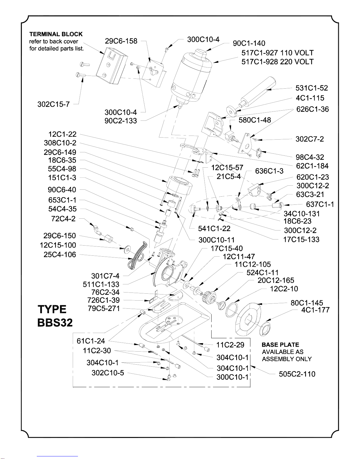
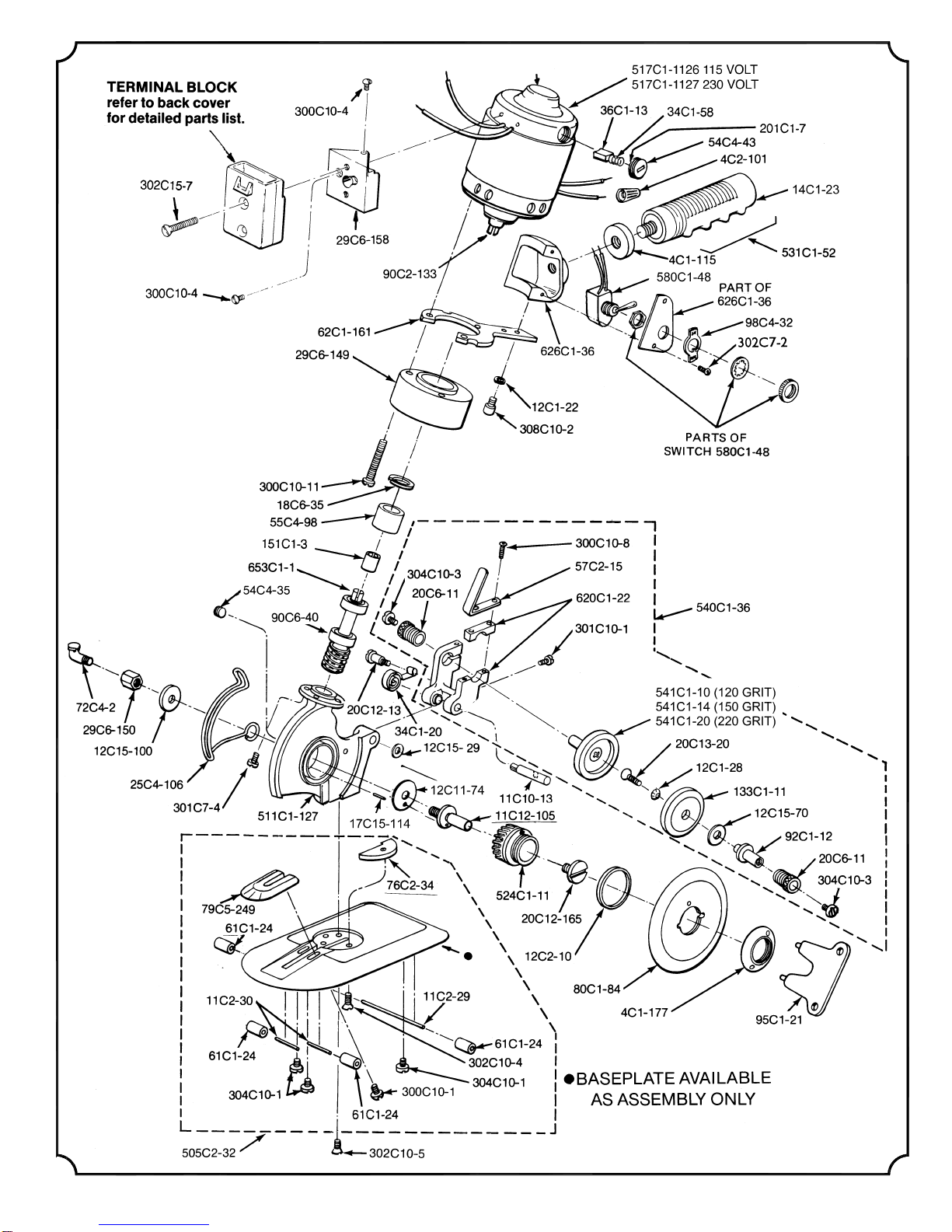
ILLUSTRATED
PARTS LIST