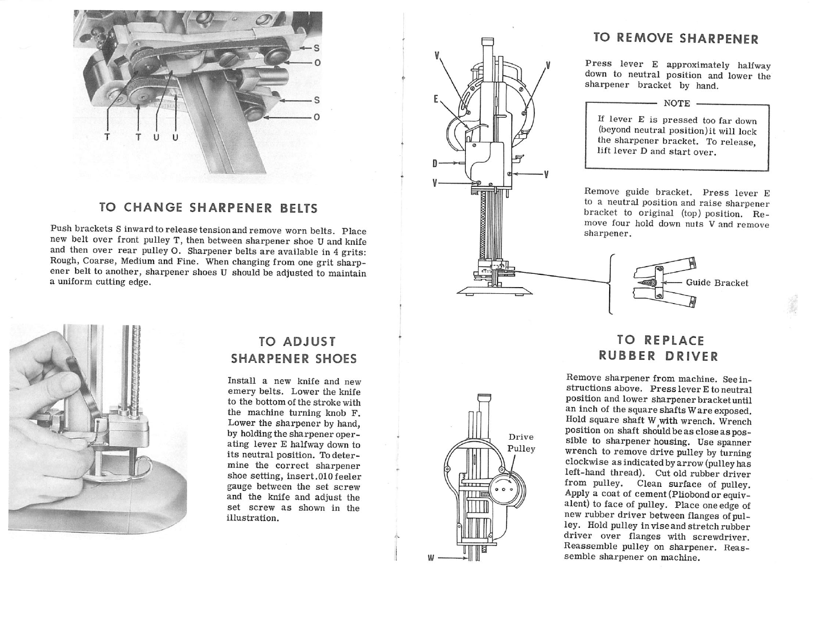
EASTMAN Blue Streak Series User manual

etSTMAN

OPERATION,
LUBRICATION
AND
CARE
r
BLUE
STREAK
CLASS
555,
565,
and
623
BEFORE
STARTING
IN
COLD
WEATHER,
PLEASE
KEEP
MACHINE
IN
WARM
PLACE
Fill
oil cups A, B and C. Make
sure
sharpener
is
in locked position.
If
sharpener
is
not in locked
position,
trip
lock
lever
D
up,
then
press
sharpener
operating
lever
E
halfway
down
and
move
sharpener
up
into
locked
position.
Push
in
turning
knob
F
and
turn
the
machine
over
a
few
revolutions
by hand to
see
if knife
moves
easily.
Connect
attach
ment
plug
and
start
machine.
WARNING
For
3-phase
machines
direction
of
rotation
must
be
as
indicated
by
arrow
on
turning
knob F. See
tag
attached
to
all
3-phase
machines
for
instructions.
For
the
first
week
or
two,
or
after
the machine
has
been
idle
for
any
length
of
time,
the
motor
should
be
turned
on
and
off
a
few
times
before
allowing it to
run
continuously.
This
permits
the
oil
to
warm
up
and
flow
easily
into
the
closely
fit
moving
parts.
LUBRICATION
EVERY
2
HOURS
-
DAILY
ONCE
A
WEEK
ONCE
A
MONTH
Fill
oil
cups
A-B-C.
Oil
connecting
rod
bearing
G.
To
oil,
drop
pressure
foot
rod
and
turn
crank
until
you
see
connecting
rod
shaft
through
hole
G.
Use
can
with
small
spout
(furnished
with
machine).
Insert
spout
in
hole
in
shaft
and
oil.
One
drop
only
to:
Tubes
at
K & L
Turning
Knob
at
M
Pulley
Shaft
N
Belt
Pulleys
O
Remove
plug
at
P
and
insert
grease
tube.
Squeeze
an
amount
about
e-
qual
to
the
size
of
a
pea
into
opening.
DO
NOT
USE
AN
EXCESS
AMOUNT
OF
OIL
CAUTION
Do not
use
sewing machine
oil.
It
is
entirely
too light
for
cutting machine lubrication.
For
best
results
use specially
compounded
Eastman
oil
or
at
least
a good
grade
of No. 30
motor
oil.
CARE
OF
MACHINE
Use
air
hose
or
bellows and blow lint out of motor and sharpener
twice
a
week.
Remove
cover
Q
and
clean
out
lint
around
screw
mech
anism
in
sharpener
once
a
week.
Remove
knife
and
clean
knife
slides
with
slot
cleaner
at
least
once aday. Remove
lint
from
rollers
in
base
plate as necessary. To prevent undue accumulation of lint, do not oil
plate rollers. If
rollers
stick, remove from plate and wash in cleaning
solvent.
TO
SHARPEN
THE
KNIFE
Take the machine out of the lay. Drop
pressure
foot by means of
pres
sure
foot
lever
R
located
nextto
machine
operating
handle.
Press
lever
E downward with a slow,
firm
pressure
to
eng^e
sharpening mechan
ism. Too fast
lever
action may cause
lever
to lock. If
this
occurs, lift
lever D and
start
over. After afew
tries
you will feel
correct
operating
pressure.
WARNING
Do
not
operate
sharpener
without
knife
in
machine
or
the
sharpener
will
be
damaged.
Do
not
shut
off
motor
while
sharpener
is
in
motion.

fwr
>
— \
TO
CHANGE
SHARPENER
BELTS
Push
brackets
Sinward to
release
tensionand remove worn
belts.
Place
new belt over front pulley T, then between
sharpener
shoe U and knife
and then over
rear
pulley O. Sharpener belts
are
available in 4 grits:
Rough,
Coarse, Medium and Fine. When changing from one
grit
sharp
ener
belt to another, sharpener shoes U should be adjusted to maintain
a
uniform
cutting
edge.
TO
ADJUST
SHARPENER
SHOES
Install
a
new
knife
and
new
emery
belts.
Lower
the
knife
to
the
bottom
of
the
stroke
with
the
machine
turning
knob
F.
Lower
the
sharpener
by hand,
by
holding
the
sharpener
oper
ating
lever
E
halfway
down
to
its
neutral
position.
To
deter
mine
the
correct
sharpener
shoe
setting,
insert
.010
feeler
gauge
between
the
set
screw
and
the
knife
and
adjust
the
set
screw
as
shown
in
the
illustration.
Drive
Pulley
TO
REMOVE
SHARPENER
Press
lever Eapproximately halfway
down to
neutral
position
and
lower
the
sharpener
bracket
by hand.
NOTE
If
lever
E
is
pressed
too
far
down
(beyond
neutral position)it will lock
the sharpener bracket. To release,
lift
lever
D
and
start
over.
Remove
guide
bracket.
Press
lever
E
to a
neutral
position
and
raise
sharpener
bracket
to
original
(top)
position.
Re
move
four
hold
down
nuts
V
and
remove
sharpener.
Guide
Bracket
TO
REPLACE
RUBBER
DRIVER
Remove
sharpener
from
machine.
See
in
structions
above.
Press
lever
E
to
neutral
position
and
lower
sharpenerbracketuntil
an inch of the squareshaftsW
are
ejqjosed.
Hold
square
shaft
Wwth
wrench.
Wrench
position on shaft should be as close
as
pos
sible to
sharpener
housing. Use spanner
wrench to remove
drive
pulley by turning
clockwise as indicated byarrow(pulleyhas
left-hand
thread).
Cut
old
rubber
driver
from pulley. Clean surface of pulley.
Apply
a coat of cement(Pliobondor equiv
alent) to face of pulley. Place oneedgeof
new rubber
driver
between flanges ofpul
ley.
Hold
pulley
in
vise
and
stretch
inibber
driver
over
flanges
with
screwdriver.
Reassemble
pulley on
sharpener.
Reas
semble
sharpener
on
machine.

TO
CHANGE
THE
KNIFE
Make
sure
sharpener
is
in locked position.
Raise
pressure
foot X to
top position by
means
of
pressure
foot
lever
R. Lay
machine
on
table
as shown.
Press
in
turning
knob F and
turn
knife to
bottom
position.
Insert
T-handle
knife
bolt
wrench
Y
as
shown
and
loosen
knife
locknut
(1).
Remove
knife through bottom of standard Z. After removing
knife,
clean
knife
slot
in
standard
with
slot
cleaner
(2).
Insert
new
knife in knife slot. Be
sure
to
set
knife tightly up against knife holding
stud
and at
the
same
time
hold the bottom of the knife
against
the
back
of the
slot
in the
standard
when tightening knife locknut. After tighten
ing knife locknut, check to see if knife runs freely in standard by ro
tating turning knob. Install new
sharpener
belts
and
operate
sharpener
three
or
four
times
before
starting
to
cut.
TO
FREE
FROZEN
GUIDES
Remove
sharpener
from
machine
as
explained previously. Remove
knife.
Loosen
screws
(3)
and
remove
connecting
rod
(4).
Insert
drift
pin
in
hole
(5) in
crank
and
tap
with
light
hammer
in
direction
of
arrow.
This
will
loosen
crank.
Remove
crank.
Loosen
set
screw
(6)
using
No. 564
Allen
Key (.078 dia.)
and
remove
oiler
and tube (7).
Remove
oil
pad
holder
(8).
Remove
crosshead(9)from
guides.
Use a
fiber
or
brass
rod
against
the
bottom
of
crosshead
and
drive
crosshead
out
through
the
top
of
the
guides.
——
NOTE
———
If
wrist
pin
is
frozen
in
crosshead,
drive
wrist
pin
out of
crosshead
with
soft
punch.
Polish
wrist
pin
and
hole
in
crosshead
with
fine
emery
cloth.
Hone
rough
spot
on
bearing
surface
of
crosshead
against
a
flat
oil
stone until smooth. Examine guides. If any evidence of high spot,
remove
with
scraper
and
clean.
Oil
bearing
surface
of
guides,
insert
crosshead
and
reassemble
machine. Be
sure
washer
(10) is in place
between
connecting
rod
and
crosshead.
^
CAUTION
1
Wrist
pin
must
be
installed
with notch (11)
at
top
center.
Otherwise
flow of
oil
to
wrist
pin
bearing
will
be
cut
off.
Run machine for approximately one-half hour, oiling guides frequently

I
8s—n
MOTOR
ASSEMBLY,
CLASS
623
(FOR
CLASS
555
AND
565
SEE
PAGE
17)
list
No.
Part
Description
Part
No.
IS
Rotor
with
Shaft
512C1-X
2S
Rotor
Fan
lOCl-X
3S
Rear
Ball
Bearing
Sprii^
Washer
12C1-12
4S
Shaft
Lock
Nut
4C1-145
6S
Stater
with
Band
514C3-X
7S
Front
to
Rear
Bearing
Screws
(4)
20C3-23
8S
Front
to
Rear
Bearing
Nut (4)
4C1-99
OS
Turning
Knob
13C1-9
118
Clutch
Nut
4C2-87
13S
Cut-Out
Switch
Insulation
8C5-3
148
Carrying
Ifendle
Screws
(4)
8-32x5/8RH.
15S
Cover
Over
Stator
Band
Screws
(4)
4-36X-L/8RH,
16S
Cover
Over
Stator
Band
53C11-65
17S
Carryii^
Handle
22C1-24
18S
Dust
Cap
Screws
(3)
4-36x5/8
FiLH.
19S
Rear
Bearing
Housing
90C1-X
;
2
IS
Automatic
Cut-Out
Switch
to
Bearing
Screws
(2)
8x32x5/8Ra
23S
Screw
for
Rear
Bearing
Lock
Nut
4-36xl/4Fil.H.
25S
Retaining
Ring
1.8C6-16
26S
Rear
Ball
Bearing
90C6-28
27S
Clutch
Spring
34C1-51
28S*
Automatic
Cut-Out
597C2-1*
29S
Automatic
Cut-Out
Switch
580C1-46
30S
Automatic
Cut-Out
Terminal
Screws
(2)
20C12-2
31S
Dust
Cap
30C1-6D
*
Please
Specify If
for
1800
RPM
or
50
Cycle
Machines
IMPORTANT
ORDERING
INSTRUCTIONS
Number
In
parenthesis
indicotes
number
of
ports
per
ossembly.
Where
the
letter
X
follows
a
port
num-

37S
423
533
543
38S
1
433
O
553
zzs
\
&
35S
I
III
W
39S
1
Fl
443
523
513
I
563
563
573
408
1
603
4IS
•463
473
613
i
o
f-62S
CH-63S
CRANK
AND
GUIDE
ASSEMBLY
List
No.
Part
Description
Part
No.
32S
8crew
for
Brg.
Shaft
20C12-78
33S
Crank
Ball
Bearing
90C6
34S
Crank
85C1-X
35S
Shaft
for
Ball
Bearing
11C12-27
36S
Crank
Ball
Bearing
Lock
Nut
4C1-132
37S
Oil
Pad
Holder
727C1-5
38S
Oil
Pad
Holder
Screws
(2)
4-36xl/4R.H.
398
Knife
Lock
Washer
12C1-24
408
Wrist
Pin
Plug
54C4-32
418
Wrist
Pin
17C4-6
428
Guide Hold Down
Screws
(2)
20C12-122
438
Nut
for
Guide
Screw
(3)
4C2-91
448
Guide
Hold
Down
Screws
(4)
20C12-123
458
Cross
Head
579C2-17
468
Knife
Stud
Nut-.
4C2
•
478
Cross
Head
Stud,
15C11.
488
Guide
Washers
(4)
12C15-14
498
Guide
Adjustment
Screws
(3)
20C13-15
508
Oil
Cup (R. H.
Guide)
72C4-16
518
Oil
Tube
(L. H.
Guide)
73C1-3
528
Guide
Adjusting
Nut
(3)
4C3-8
538
L.
H.
Guide
70C1-X
548
Guide
Lock
Screws
(3)
20C13-14
558
R.
H.
Guide
70C1-X
568
Oil Cup (L. H. Guide &
Crosshead)
(2)
72C4-15
578
Oil
Tube
(L.
H.
Guide)
73C1-7
588
Oil
Tube
for
Wrist
Pin
73C7-X
.
598
Oil
Tube
for
Wrist
Pin
73C6-X
60S
Connecting
Rod
664C1-X
618
Connecting
Rod
Washer
12C15-53
628
Connecting
Rod
Clamp
Screw
(2)
20C5-17
638
Shakeproof
Washer
12C1-21
IMPORTANT ORDERING INSTRUCTIONS
Number
In
parenthesis
Indicates
number
of
parts
per
assembly.
Where
the
letter
X
follows
a
part
num
ber,
be
sure
to
give
the
model
and
serial
numbers
shown
on
the
machine
for
which
the
part
is
required.

tiTPir
—
FRONT
BEARING
HOUSING
7 -
r'
Wr3S
75S 755 \ ^
TAC/^
175
List
No.
Part
Description
Part
No,
65S
Front
Ball
Bearing
90C6-29
66S
Operating
Handle
531C1-37
67S
Stud,
Lower
L. H. Mounting
15C13-34
68S
Lower
L,
H.
Sharpener
hold
down
Nut
4C1-150
69S
Front
Bearing
Housing
90C2-X
71S
Front
Ball
Bearing
Retainer
71C3-5
72S
Operating
Handle
Lock
Nut
4C1-111
73S
Standard-to-Bearing
Pin
(2)
17Cf-5
74S
Standard-to-Bearing
Screws
(4)
20C12-39
75S
Stud,
Guard
Rod
Bracket
(2)
15C13-39
76S
Set
Screw
20C13-4
77S
Front
Ball
Bearing
Retainer
Screws
6-32x5/16Fl.H.
78S
Stud,
Upper
(2)
15C13-23
79S
Sharpener
hold down
Nuts
(3)
4C1-99
IMPORTANT ORDERING INSTRUCTIONS
Number
in
parenthesis
Indicates
number
of
ports
per
assembly.
Where
the
letter
X
follows
o
port
num
ber.
be sure to
alve
the model and serial numbers shown on fhfl
rnacKinA
for
wKioU
nnri
rAnnirArl
TERMINAL
BLOCK,
ATTACHMENT
PLUG
AND
SWITCH
84S
8SS
B
82S-
HHP
86S
/ ^
f
87$
n
in
92S
93S 94S 95S 96S 98S 99S
List
No.
SINGLE
PHASE
PARTS
Part
Description
Switch
Base
Switch
Cover
Switch Cover
Screws
(3)
Switch Base Screws (4)
Terminal Block (Complete)
Terminal
Block (top) _
Terminal
Block (bottom)
Switch
Screws
(2)
Switch
Ground
Clip
Terminal
Pin
(2)
Terminal
Sleeve
(2)
Attachment Plug (Complete)
Attachment
Plug
Clamp
Terminal Contact with Pin
(2)
Terminal
Contact
Terminal
Screws
(2)
Terminal Block Screw (1)
Ground Clip Screw (1)
Part
No.
52C5-X
53C2-X
4-36X1/40.H.
4-36xl/40.H.
508C1-19
51C1-16
-
51C1-17
4-36X1/4R.H.
580C1-14
79C12-107
47C2-4
47C3-16
523C1-51
615C1-7
667C1
93C2-1
20C12-2
10-32x7/8Fl.H.
10-32x1
Fil.H.

t09S
ft
i20S
lOOS
I
i04S
I05S
I06S
II8S
I20S
I
I07S
I08S
Ocri
*
TERMINAL
BLOCK,
ATTACHMENT
PLUG
AND
SWITCH
THREE
PHASE
PARTS
List
No.
Part
Description
Part
No.
lOOS
Attachment
Plug
Complete
523C1-38
lOlS
Ground
Clip
79C12-106
102S
Contact
with
Pin
-
Left
Hand
667C1-3
103S
Contact
with
Pin
-
Right
Hand
667C1-1
104S
Contact
with
Pin
-
Center
667C1-2
105S
Screws
for
Terminal
Block
(2)
10-32xl-l/8"Fil.H.
106S
Screws
for
Terminal
Block
(2)
10-32xl-l/8Fl.H.
107S
Terminal
Pin
(3)
47C2-9
108S
Attachment
Pli^
Terminal
Sleeve
(3)
47C3-17
logs
Switch
Base
52C5-X
HQS
Switch
Base
Screws
(3)
4-36xl/40.H.
Ills
Switch
Cover
53C2-X
112S
Switch
Cover
Screws
(4)
4-36xl/40.H.
113S
3-Phase
Switch
Complete
580C1-11
114S
Switch
to
Base
Screws
(4)
4-36xl/4R.H.
115S
Terminal
Block Complete ^
508C1-22
lies
Terminal
Block
(Top)
51C1-18
117S
Terminal
Block
(Bottom)
51C1-19
118S
Attachment
Plug
Clamp
615C1-5
119S
Terminal
Block
Adapter
29C6-67
120S
Insulation
for
3-phase
parts
Small
Insulation
8C4-11
Large
Insulation
8C4-37
IMPORTANT
ORDERING
INSTRUCTIONS
Number
In
parenthesis
Indicates
number
of
parts
per
assembly.
Where
the
letter
X
follows
a
part
num
ber, be
sure
to
give
the
model
ond
serial
numbers
shown
onthe
machine
for
which
thepartis
required.

I33S
1348
I 6
o "
I25S
I30S
I36S
1373
MOTOR
ASSEMBLY,
CLASS
555
AND
565
(FOR
CLASS
623
SEE
PAGE
9)
List
No.
Part
Description
Rotor
With
Shaft
Rear
Bearing
Cap
Cutout
Block
Assembly
Rear
Ball
Bearing
Shaft
Lock
Nut
Tension
Spring
Turning
Knob
Rear
Bearing
Housing
Cutout
Cover
Cutout
Cover
Screws
(3)
Clutch
Disk
Clutch
Nut
Stator
Ring
Automatic
Cutout
Grommet
Part
No.
lOCl-X
513C3-X
86C3-15
733C1
gOC6-28
4C1-145
34C1-51
13C1-7
90C1-112
53C11-41
4-36xl/4Fl.H.
115C1-7
4C2-87
18C2-X
597C1-10
575C1-X
207C1
IMPORTANT ORDERING INSTRUCTIONS
Number
in
parenthesis
indicates
number
of
ports
per
assembly.
Where
the
letter
X
follows
a
port
num
ber,be
sure
to
give
the
model
and
serial
numbers
shown
onthe
machine
for
which
the
part
is
required.

I49S
I50S
I52S I53S
i i
I63S
1648
STANDARD
AND
BASE
PLATES
List
No.
Part
Description
Part
No.
BASE
PLATE
(RUBBER
MOUNTED
ROLLERS)
Hinge
Pin
Clamp
Screw
(2)
20C13-24
Hinge
Pin,
Short
(2)
17C6
Plate
Wing
60C1-XR
Plate
Wing
Tension
Spring
(2)
34C1-57
Rubber
Mounted
Roller
(Complete)
532C2-3
Plate
Complete
(Rubber
Mounted
Rollers)
505C3-XR
Clamp
Screws
lor
Rollers
(8)
20C5-12
STANDARD
149S
Standard
to
Bearing
(4)
Screws
20C12-39
150S*
Standard
(Complete
with
Knife
528C1-X*
Slides
and
Throat
Plates)
151S
Knife
Slide
Screw
20C12-19
152S
Plate
Bolt
24C4
153S
Plate
Bolt
Nut
4C2-2
154S
*
Knife
Slides
(Complete
with
Screws)
643C1-X*
155S
Throat
Plates
With
Screws
and
Pins
79C4-12/13
*
Specify
Knife
Size
When
Ordering
Standard
or
Knife
Slides
BASE
PLATE
(SPRING MOUNTED ROLLERS)
Plate
Wing
60C1-XS
Plate
Wing
Tension
Spring
Screw
(1)
6-32xl/4R.H.
Plate
Wing
Tension
Spring
34C1-2
Plate
Roller
Complete
(2)
532C1-X
Plate
Complete
(Spring
Roller
Type)
505C3-XS
Plate
Roller
Screw
(4)
20C5-18
Hinge
Pin
Clamp
Screw
(4)
20C5
Hinge
Pin
(2)
17C6
IMPORTANT
ORDERING
INSTRUCTIONS
Number
In
porenthesis
indicates
number
of
ports
per
assembly.
Where
the letterX
follows
a port
num
ber. be sure to alve the modelond serial
numbers
shownon the machine for which the oart is reauired.

l93S-^_
1733
I94S
2008
1998
2018
leos
»77S
i
I70S
I7IS
I72S
i i f
^I69SA
X
q^I74S
I78S I75S
VI
I8IS
I82S
i i
"
I85S
I90S
I9IS
I76S
jj
i
(83S
L §
I88S
^
I92S
/
if
I86S
1
1848
t
I95S
^
2048
1968
^ +
I
.5^
2028
2038
204SA
I i
I
2^8
2068
AUTOMATIC
SHARPENER
ASSEMBLY
List
No.
Part
Description
Part
No.
168S
Screw
for
Release
Lever
20C12-119
169S
Release
Lever
with
Cam
621C1-7
legsa
Set
Screw
for
Cam
20C12-118
170S
Bearing
for
Cam
Shaft
(Rear)
90C4-43
171S
Bearing
for
Cam
Shaft
(Front)
90C4-44
172S
Spring
for
Latch
34C10-107
173S
Pres.
Foot
Lock
Bracket
Screws
(4)
6-32x5/16R.H.
174S
Spring
Washer
for
Release
Lever
12C15-57
175S
Latch
for
Cam
97C3-35
176S
Screw
for
Pressure
Foot
Lock
20C12-137
177S
Stud
for
Release
Lever
15C13-38
178S
Screw
for
Latch
20C12-113
179S
Cam
Spring
34C1-20
180S
Shaft
for
Cam
11C12-54
181S
Sharpener
Hold
Down
Nuts
(3)
4C1-99
182S
Sharpener
Hold
Down
Nut
4C1-150
183S
Washer
for
Lock
Bracket
12C15-69
184S
Spacer
Tube
73C7-X
185S
Pressure
Foot
Lock
Bracket
553C1-8
186S
Screw
Shaft
Extension
147C1-26
187S
Cam
Shaft
Spring
Screw
20C12-13
188S
Nut
(6-32
Flexlock)
for
Pres.
Ft.
Lock
4Cl-16i
189S
Pressure
Foot
Lever
Screw
20C4-17
190S
Pressure
Foot
Lever
57C7-39
191S
Spring
for
Pressure
Foot
Lock
34C8-12
192S
Lock
(only)
Pressure
Foot
171C1-16
193S
Pressure
Foot
Lock
Bracket
(complete)
553C1-7
194S
Spring
for
Pressure
Foot
Lever
34C10-100
195S
Slide
for
Pressure
Foot
Rod
66C1-52
196S
Bearing
for
Screw
Shaft
90C4-58
197S
Thrust
Ball
Bearing
(2)
658C1-1
198S*
Pressure
Foot
Rod
605C1-X*
199S
Screw
(2)
for
Pressure
Foot
Shoe
20C12-117
200S
Pressure
Foot
Shoe
68C1-183
201S
Screw
for
Cover
6-32x3/4Fl.H.
202S
Cover
Over
Cam
53C11-72
203S
Screw
for
Cover
6-32x3/8Fl.H.
204S
Nut
for
Screw
Shaft
L.H.
4C2-90
204Sa
Thrust
Washer
for
Nuts
12C15-54
205S
Nut
for
Screw
Shaft
R.H.
4C2-89
206S*
Screw
Shaft
with
Extension
713C2-X*
207S
Stop
Nut
for
Screw
Shaft
4C1-149
IMPORTANT ORDERING INSTRUCTIONS
Number
in
porenthesis
Indicotes
number
of
ports
per
ossembly.
Where
the
letter
X
follows
o
port
num-

242S.
246S
2I0S
j
2I4S
220S
22IS
2I7S
11
2I9S 2I9SA
224S
222S
i A ^
II
223S
«,ocA
" "
223S
'"i
"
2I6S
226S
-i
227S
238S
f
2i8S
233S
225S
235S
9 I r ?
234S
n
2363
2378
240Ss,
a © Ov
2393
^^2448
¥
248S
b ?
3
243S
245S
SHARPENER
HOUSING
AND
BELL
CRANK
ASSEMBLY
List
No.
Part
Description
Part
No.
210S
Sharpener
Housing
732C1-X
211S
Push
Rod
65C6-75
212S
Oil
Pad
&
Holder
727C1-6
213S
Cover
for
Driver
53C11-X
214S
Bearing
for
Push
Rod
(2)
90C4-41
215S
Cap
for
Tube
86C7-22
216S
Screw
for
Spreader
Pin
6-32xl/2Fl.H.
217S
Roll
Pin
for
Push
Rod
17C15-103
218S
Driver
Shaft
with
Gear
716C1-12
218Sa
Thrust
Washer
12C15-29
219S
Bearing
for
Drive
Shaft
(Upper)
90C4-48
219Sa
Bearing
for
Drive
Shaft
90C4-42
220S
Screws
(2)
for
Oil
Pad
6-32X1/4R.H.
221S
Screws
(2)
for
Cover
4-36x1/8R.H.
222S
Right
Hand
Follower
Nut
4C2-85
223S
Bushing
for
Drive
Shaft
(Lower)
9QC4-29
224S
Left
Hand
Follower
Nut
4C2-86
225S
Spreader
Pin
17C15-113
226S
Bearing
for
Gears
(2)
90C4-33
227S
Bottom
Plate
79C12-163
228S
Bottom
Plate
Screws
(3)
8-32x1/4F1.H.
229S
R.H. &L.H.
Square
Shaft
5"-6"-7"-8"
11C12XS
230S
R.H.
&
L.H,
Square
Shaft
9"
&
10"
11C12XL
231S
(Specify "Right"
or
"Left" when
ordering
parts)
Spur
Gear
(2)
87C3-44
232S*
Bell
Crank
Complete
584C3-14*
233S
Spring
for
Bell
Crank
34C10-89
234S
Spacer
for
Ball
Bearings
90C6-24
55C4-41
235S*
Gear
&
Shaft
87C3-42*
236S
Retaining
Ring
for
11C12-64
18C6-8
237S
Washer
for
11C12-64
12C15-52
238S
Lock
Nut
for
Ball
Bearing
90C6-24
4C1-143
239S
L.H.
Spiral
Gear
with
Key
724C1-3
240S
Ball
Bearing
for
Crank
(2)
90C6-24
241S
Bearing
for
Gear
627C1-5
90C4-53
242S
Idler
Gear
with
Bushing
627C1-5
243S
Lock
Nut
for
Crank
Shaft
4C1-147
244S
Shaft
for
Crank
11C12-64
245S
Bearing
for
Crank
9QC4-34
246S*
Bell
Crank
with
Pin
&
Bushing
584C2-1*
247S*
Rubber
Drivers
200C1-9*
248S*
Driver
Pulley
with
Driver
602C1-7*
* For 1800 RPM Machines, Please List 1800 RPM Before
Part
Number

25IS
252S
250S
258S
259S
260S
26IS
262S
2638
2648
2658
2668
1
2678
1
2698
2728
2738
2788
2798 2808
i
2688
2758
2748
275SA
2768
6 6
2818
2828
- 1
2848
2778
6
2838
LOWER
GEAR
BRACKET
ASSEMBLY
List
No.
Part
Description
Part
No.
2 SOS
Lower
Gear
Bracket
(Complete)
715C1-10
2518
8crew
(1)
for
Gear
Cover
(53C4-76)
6-32x3/8
Fil.H.
252S
Lower
Gear
Bracket
with
Cover
715C1-11
•
253S
Grease
Plug
54C4-35
254S
Guide
Back
of
Standard
70C4-23
2558
Lower
Gear
Bracket
Gear
Cover
53C4-76
256S
Screws
(2)
for
Guide
Back
(70C4-23)
6-32xl/4R,H.
257S
Adjusting
Screw
20C6-22
2588
Screws
(3)
for
Gear
Cover
(53C4-76)
6-32xl/2R.H.
2598
Clamping
Arm
for
Shoe
35C7-26
2608
Screw
for
Clamping
Arm
20C12-143
2618
Spring
for
Arm
34C10-123
2628
Stabilizers
(2)
728C1-5
2638
Screws
(4) for
Stabilizers
(728C1-5)
4-36xl/4Fil.H.
2648
Bearing
for
Intermediate
Gear
(87C5-
-13)
90C4-47
-
2658
Intermediate
Gear
87C5-13
2668
R.H.
Shaft
Extension
147C1-28
V
2678
Collar
for
Lower
Screw
Shaft
(713C2-
•X)
5C5-16
2688
Bearings
(2)
for
Shaft
Extension
90C4-59
-
2698
L.H.
Shaft
Extension
147C1-29
^
2708
Nuts
(2)
for
Sharpener
Shoes
Screws
4C2-63
2718
Screws
(2)
for
Sharpener
Shoes
20C12-57
2728
L.H.
Sharpener
Shoe
Spring
34C10-47
2738
R.H.
Sharpener
Shoe
Spring
34C10-57
2748
Neoprene
Bands
(2)
for
Pulley
209C1
2758
Front
Pulleys
(2)
for
Belts
152C1-19
275Sa
Roll
Pin
(2)
for
Pulleys
(152C1-19)
17C15-103
2768
Bearing
for
Screw
Shaft
90C4-51
^ ,
2778
Gear
on
Screw
Shaft
2788
L.H.
Slide
with
Pulley
712C1-1
2798'
R.H.
Slide
with
Pulley
712C1
2803
.
Spring
(2)
for
Pulley
Slide
34C10-45
2818
L.H,
Shoe
for
Plastic
Master
&
Bushing
743C1-4
2828
L.H.
Shoe
with
Bushing
743C1-18
2838
RJl.
Shoe
with
Bushing
743C1-11
2848
Set
Screw
(1)
for
Sharpener
Shoes
20C13-4
IMPORTANT ORDERING INSTRUCTIONS
Number
In
parenthesis
Indicates
number
of
ports
per
assembly.
Where
the
letter
X
follows
a
part
num
ber,
be
sure
to
give
the
model
and
serial
numbers
shown
on
the
machine
for
which
the
port
Is
required.

[
EASTMAN
OIL
HSIMI
MCWIir ci
I4A
List
No.
ACCESSORIES
Part
Description
Knife
Bolt
Wrench
Plate
Bolt
Wrench
Trolley
Pulley
Allen
Wrench
for
Shoe
Set
Screws
Oiling Device
^0"^
~
Eastman
Bearing
Grease
Abrasive
Belts
(See
Page
28)
Sharpener
Cleaning
Brush
Feeler
Guage
for
Shoe
Set
Screws
Trolley
Hook
Oil
Can
Turnbuckle
1/2
Pint
Eastman
Oil
Swivel
Snap
Slot
Cleaner
Trolley
Spring

KNIVES
AND
ABRASIVE
BELTS
SIZE
TYPE
,
CARBON
!
HIGH
SPEED
SPEOIAL
ALLOY
5"
Straight
80C5
8005HS
8005SA
5"
Saw
Tooth
80C5-14
80C5-14HS
5"
Wave
8005-19
80O5-19HS
6"
Straight
8006
80C6HS
80C6SA
6"
Saw
Tooth
B0O6-14
80O6-14HS
6"
Wave
8006-19
8006-19HS
Straight
80C7
80C7HS
80C7SA
Saw
Tooth
80C7-14
Wave
80C7-19
80C7-19HS
m
Straight
80O8
80C8HS
•
80C8SA
8"
Saw
Tooth
8008-7
8"
Wave
80C8-19
80C8-19HS
g
Straight
80C9
80O9HS
800
9SA
m
Wave
8009-19
80C9-19HS
Straight
80C10
80C10HS
80010SA
W^m
Wave
80010-19
80010-19HS
Rough
Coarse
Medium
Fine
ABRASIVE
SHARPENING
BELTS
(Packed
in
Boxes
of
100)
COLOR
CODE
Black
Red
Green
Blue
NUMBER
181C1-6
181C2-1
181C2-2
181C2-5
This manual suits for next models
3
Table of contents
Other EASTMAN Power Tools manuals