manuals.online logo
Brands
  1. Home
  2. •
  3. Brands
  4. •
  5. Eaton
  6. •
  7. Cables And Connectors
  8. •
  9. Eaton COOPER POWER SERIES User manual

Eaton COOPER POWER SERIES User manual

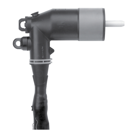
DPC400 & DPC436 Connecting plug installation instructions
DT400 24 kV
COOPER POWER
SERIES
DPC400 & DPC436
Connecting Plug
MN650033EN Effective November 2016
Supersedes July 1999 (IS550-31-1)
iINSTALLATION INSTRUCTIONS MN650033EN November 2016
DISCLAIMER OF WARRANTIES AND LIMITATION OF LIABILITY
The information, recommendations, descriptions and safety notations in this document are based on Eaton Corporation’s
(“Eaton”) experience and judgment and may not cover all contingencies. If further information is required, an Eaton sales
office should be consulted. Sale of the product shown in this literature is subject to the terms and conditions outlined in
appropriate Eaton selling policies or other contractual agreement between Eaton and the purchaser.
THERE ARE NO UNDERSTANDINGS, AGREEMENTS, WARRANTIES, EXPRESSED OR IMPLIED, INCLUDING WARRANTIES
OF FITNESS FOR A PARTICULAR PURPOSE OR MERCHANTABILITY, OTHER THAN THOSE SPECIFICALLY SET OUT IN ANY
EXISTING CONTRACT BETWEEN THE PARTIES. ANY SUCH CONTRACT STATES THE ENTIRE OBLIGATION OF EATON. THE
CONTENTS OF THIS DOCUMENT SHALL NOT BECOME PART OF OR MODIFY ANY CONTRACT BETWEEN THE PARTIES.
In no event will Eaton be responsible to the purchaser or user in contract, in tort (including negligence), strict liability or other-wise
for any special, indirect, incidental or consequential damage or loss whatsoever, including but not limited to damage or loss
of use of equipment, plant or power system, cost of capital, loss of power, additional expenses in the use of existing power
facilities, or claims against the purchaser or user by its customers resulting from the use of the information, recommendations
and descriptions contained herein. The information contained in this manual is subject to change without notice.
ii INSTALLATION INSTRUCTIONS MN650033EN November 2016
Contents
DISCLAIMER OF WARRANTIES AND LIMITATION OF LIABILITY ....................................I
SAFETY FOR LIFE .........................................................................III
SAFETY INFORMATION ....................................................................III
Safety instructions.............................................................................. iii
SEPARABLE CABLE JOINT .................................................................. 2
iiiINSTALLATION INSTRUCTIONS MN650033EN November 2016
Safety for life
!
SAFETY
FOR LIFE
!
SAFETY
FOR LIFE
Eaton’s Cooper Power series products meet or exceed all applicable industry standards relating to product safety. We
actively promote safe practices in the use and maintenance of our products through our service literature, instructional
training programs, and the continuous efforts of all Eaton employees involved in product design, manufacture, marketing and
service.
We strongly urge that you always follow all locally approved safety procedures and safety instructions when working around
high-voltage lines and equipment and support our “Safety For Life” mission.
The instructions in this manual are not intended as a
substitute for proper training or adequate experience in the
safe operation of the equipment described. Only competent
technicians, who are familiar with this equipment should
install, operate and service it.
A competent technician has these qualifications:
• Is thoroughly familiar with these instructions.
• Is trained in industry-accepted high- and low-voltage safe
operating practices and procedures.
• Is trained and authorized to energize, de-energize, clear,
and ground power distribution equipment.
• Is trained in the care and use of protective equipment
such as flash clothing, safety glasses, face shield, hard
hat, rubber gloves, clampstick, hotstick, etc.
Following is important safety information. For safe
installation and operation of this equipment, be sure to read
and understand all cautions and warnings.
Safety instructions
Following are general caution and warning statements that
apply to this equipment. Additional statements, related
to specific tasks and procedures, are located throughout
themanual.
Safety information
DANGER
Hazardous voltage. Contact with high voltage will
cause death or severe personal injury. Follow all locally
approved safety procedures when working around
high- and low-voltage lines and equipment.
WARNING
Before installing, operating, maintaining, or testing this
equipment, carefully read and understand the contents
of this manual. Improper operation, handling or
maintenance can result in death, severe personal injury,
and equipment damage.
WARNING
This equipment is not intended to protect human
life. Follow all locally approved procedures and safety
practices when installing or operating this equipment.
Failure to comply may result in death, severe personal
injury and equipment damage.
WARNING
Power distribution and transmission equipment must
be properly selected for the intended application. It
must be installed and serviced by competent personnel
who have been trained and understand proper safety
procedures. These instructions are written for such
personnel and are not a substitute for adequate training
and experience in safety procedures. Failure to properly
select, install or maintain power distribution and
transmission equipment can result in death, severe
personal injury, and equipment damage.
This manual may contain four types of hazard statements:
DANGER
Indicates a hazardous situation which, if not avoided,
will result in death or serious injury.
WARNING
Indicates a hazardous situation which, if not avoided,
could result in death or serious injury.
CAUTION
Indicates a hazardous situation which, if not avoided,
may result in minor or moderate injury.
CAUTION
Indicates a hazardous situation which, if not avoided,
may result in equipment damage only.
Hazard Statement Definitions
1
DPC400 & DPC436 Connecting plug installation instructions
INSTALLATION INSTRUCTIONS MN650033EN November 2016
Complete connector kit includes:
1 – connecting plug
– silicone lubricant
– paper towel
– installation instructions
Dual Cable arrangement on apparatus
Step 1
1. Install a tee connector to the first cable and the apparatus
bushing in accordance with the instructions supplied with
the tee, but do not install the basic insulating plug or
rubbercap.
Step 2
1. Clean the exposed tee interface and one interface of the connecting plug with a lint-free cloth and apply a thin layer of
supplied silicone lubricant to each.
2. Insert the connecting plug into the tee and engage the threads of the clamping screw, taking care to avoid
cross-threading.
3. Tighten the connecting plug to a torque of 50 Nm with a 10 mm hex wrench.
4. Install the second tee connector, including the basic insulating plug and rubber cap, to the second cable and the
remaining connecting plug interface. Ensure thatthe long side of the clamping screw is inserted through the crimp
connector and into the connectingplug.
DT400 24 kV
DT400 24 kV
DT400 24 kV
tee installed
on bushing
and cable #1
BIP clamping
screw
rubber
cap connecting
plug
tee installed
on cable #2
2
DPC400 & DPC436 Connecting plug installation instructions
INSTALLATION INSTRUCTIONS MN650033EN November 2016
Separable Cable Joint
Step 3
1. Prepare the first cable and install the crimp connector,
cable adapter, and moulded tee connector in
accordance with the instructions supplied with the
tee(#1).
2. Clean one interface of tee #1 and the interface of the
basic insulating plug with a lint-free cloth and apply a
thin layer of silicone lubricant to each.
3. Insert the basic insulating plug into the prepared tee
interface, through the hole in the crimp connector, and
engage the threads of the basic insulating plug. Take
care to avoid cross-threading or scratching the interface
of the tee. Tighten the clamping screw to 50 Nm.
4. Clean the other interface of tee #1 and one interface of
the connecting plug with lint-free cloth and apply a thin
layer of silicone lubricant to each.
5. Insert the connecting plug into the tee and engage the
threads of the clamping screw, taking care to avoid
cross-threading. Tighten the connecting plug to 50 Nm
with a 10 mm hex wrench.
6. Prepare the second cable and install the crimp
connector, cable adapter, and moulded tee connector
in accordance with the instructions supplied with the
tee(#2).
7. Clean one interface of tee #2 and the other connecting
plug interface. Apply a thin layer of silicone lubricant.
Install tee #2 onto the connecting plug and insert the
long end of the clamping screw through the hole in
the crimp connector and engage the threads of the
connecting plug. Take care to avoid cross-threading or
scratching the interface of the tee. Torque the clamping
screw to 50 Nm.
8. To assemble a three-way or four-way joint, repeat steps
4-7 above with additional tees and connecting plugs.
9. Clean and assemble the last moulded tee and basic
insulating plug in accordance with the instructions.
Tighten the plug to a torque of 50 Nm.
10. Clean the exterior surface of the basic insulating plugs
and the inside surface of the rubber caps. Position each
cap on a plug and push firmly until it snaps into place.
DT400 24 kV
DT400 24 kV
BIP clamping
screw clamping
screw
rubber
cap
BIP rubber
cap
connecting
plug
tee #2 installed
on cable
tee #1 installed
on cable
3
DPC400 & DPC436 Connecting plug installation instructions
INSTALLATION INSTRUCTIONS MN650033EN November 2016
This page intentionally left blank.
Eaton
1000 Eaton Boulevard
Cleveland, OH 44122
United States
Eaton.com
Eaton’s Power Systems Division
2300 Badger Drive
Waukesha, WI 53188
United States
Eaton.com/cooperpowerseries
© 2016 Eaton
All Rights Reserved
Printed in USA
Publication No. MN650033EN
November 2016
Eaton is a registered trademark.
All trademarks are property
of their respective owners.
For Eaton's Cooper Power series product
information
call 1-877-277-4636 or visit:
www.eaton.com/cooperpowerseries.
!
SAFETY
FOR LIFE

Other manuals for COOPER POWER SERIES

75

This manual suits for next models

2

Other Eaton Cables And Connectors manuals

Eaton Network Adapter FCC 15 User manual

Eaton

Eaton Network Adapter FCC 15 User manual

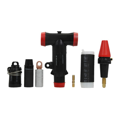
Eaton COOPER POWER SERIES User manual

Eaton

Eaton COOPER POWER SERIES User manual

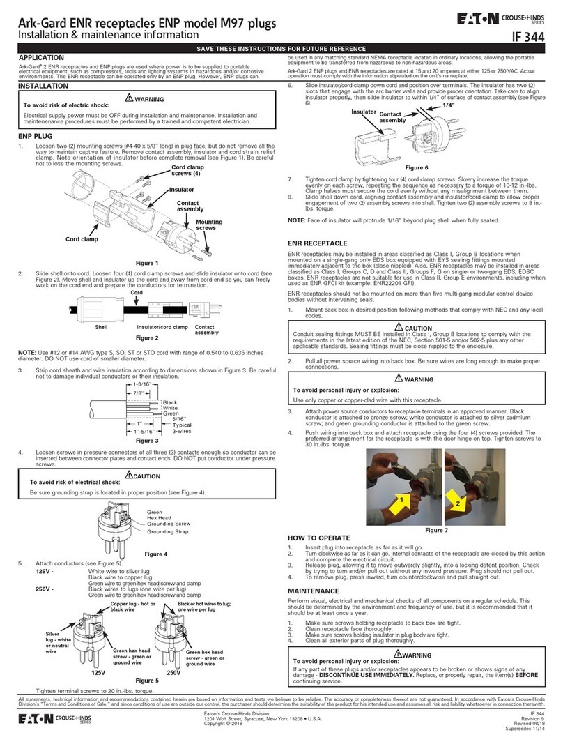
Eaton Crouse-Hinds ARK-GARD M97 Series Setup guide

Eaton

Eaton Crouse-Hinds ARK-GARD M97 Series Setup guide

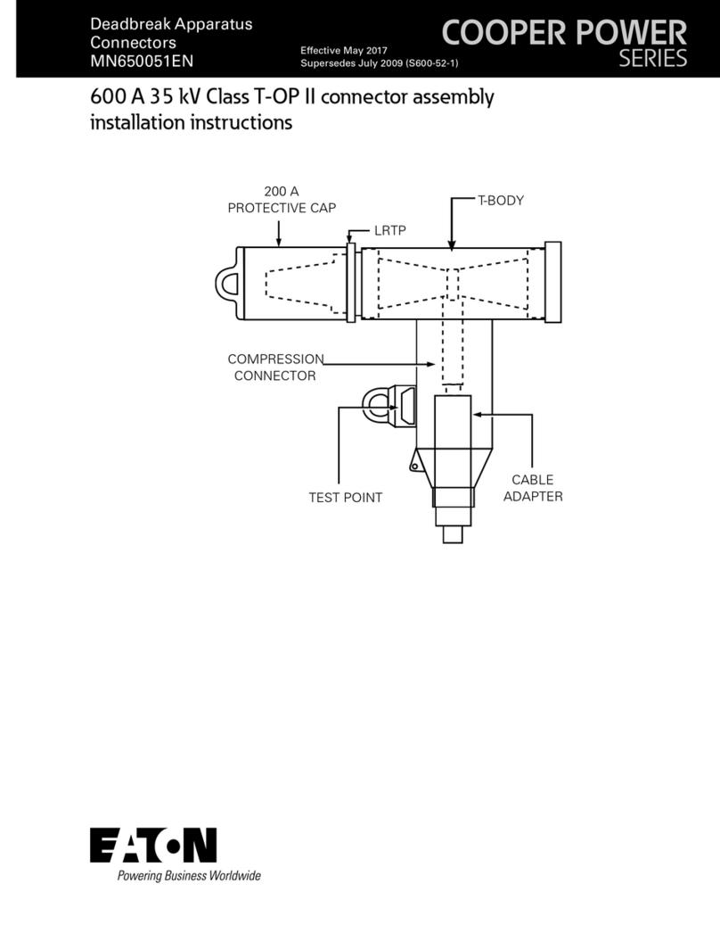
Eaton 600 A 15 kV class push-OP User manual

Eaton

Eaton 600 A 15 kV class push-OP User manual

Eaton DX-SPL-RJ45-3SL Manual

Eaton

Eaton DX-SPL-RJ45-3SL Manual

Eaton COOPER POWER SERIES User manual

Eaton

Eaton COOPER POWER SERIES User manual

Eaton COOPER POWER SERIES User manual

Eaton

Eaton COOPER POWER SERIES User manual

Eaton COOPER POWER SERIES User manual

Eaton

Eaton COOPER POWER SERIES User manual

Eaton Crouse-Hinds Ark-Gard ENR Series Setup guide

Eaton

Eaton Crouse-Hinds Ark-Gard ENR Series Setup guide

Eaton EZ II Series User manual

Eaton

Eaton EZ II Series User manual

Eaton COOPER POWER SERIES User manual

Eaton

Eaton COOPER POWER SERIES User manual

Eaton ZB4-209-DS2 Manual

Eaton

Eaton ZB4-209-DS2 Manual

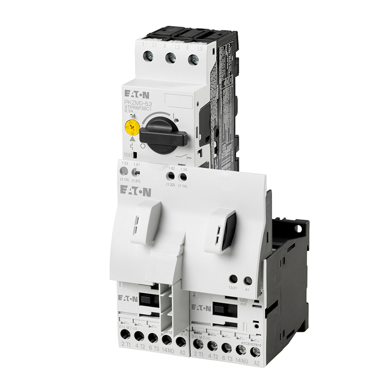
Eaton MSC-R Series Manual

Eaton

Eaton MSC-R Series Manual

Eaton EU4A-RJ45-CAB2 Manual

Eaton

Eaton EU4A-RJ45-CAB2 Manual

Eaton COOPER POWER SERIES User manual

Eaton

Eaton COOPER POWER SERIES User manual

Eaton DT400 User manual

Eaton

Eaton DT400 User manual

Eaton Roughneck IF 1683 Setup guide

Eaton

Eaton Roughneck IF 1683 Setup guide

Eaton DMM-125 SE4 Series Manual

Eaton

Eaton DMM-125 SE4 Series Manual

Eaton 600 A 35 kV Class Insulated Standoff Bushing User manual

Eaton

Eaton 600 A 35 kV Class Insulated Standoff Bushing User manual

Eaton COOPER POWER SERIES Programming manual

Eaton

Eaton COOPER POWER SERIES Programming manual

Eaton COOPER POWER SERIES User manual

Eaton

Eaton COOPER POWER SERIES User manual

Eaton COOPER POWER SERIES User manual

Eaton

Eaton COOPER POWER SERIES User manual

Eaton ZADEL-16 Manual

Eaton

Eaton ZADEL-16 Manual

Eaton ZB4-209-DS3 Manual

Eaton

Eaton ZB4-209-DS3 Manual

Popular Cables And Connectors manuals by other brands

VETEC UNI-LINK01 User instructions

VETEC

VETEC UNI-LINK01 User instructions

Philips SWV2223 Specifications

Philips

Philips SWV2223 Specifications

Knoll DIR55 instructions

Knoll

Knoll DIR55 instructions

EXEL ACOUSTICS tecnare TPB1U Operation manual

EXEL ACOUSTICS

EXEL ACOUSTICS tecnare TPB1U Operation manual

RKC INSTRUMENT SRZP-01 instruction manual

RKC INSTRUMENT

RKC INSTRUMENT SRZP-01 instruction manual

Staubli POAG-KBT6DIN Assembly instructions

Staubli

Staubli POAG-KBT6DIN Assembly instructions

Illustra Pro PTZ Quick reference guide

Illustra

Illustra Pro PTZ Quick reference guide

Leviton 113 Installation

Leviton

Leviton 113 Installation

Extron electronics STP Series Specification sheet

Extron electronics

Extron electronics STP Series Specification sheet

Appleton ATX UPR Series manual

Appleton

Appleton ATX UPR Series manual

Philips SWV3567 Specifications

Philips

Philips SWV3567 Specifications

Sirius Satellite Radio SR-100C installation guide

Sirius Satellite Radio

Sirius Satellite Radio SR-100C installation guide

HRS GT50 Series Operation manual

HRS

HRS GT50 Series Operation manual

CarlStahl 1012 Series instruction manual

CarlStahl

CarlStahl 1012 Series instruction manual

StarTech.com 1P3FPC-USB-SERIAL quick start guide

StarTech.com

StarTech.com 1P3FPC-USB-SERIAL quick start guide

KanexPro HDSP2X4 Setup guide

KanexPro

KanexPro HDSP2X4 Setup guide

Alemite 7345 Service guide

Alemite

Alemite 7345 Service guide

Metra Electronics AS-1X3TSPLIT user manual

Metra Electronics

Metra Electronics AS-1X3TSPLIT user manual

manuals.online logo
manuals.online logoBrands
  • About & Mission
  • Contact us
  • Privacy Policy
  • Terms and Conditions

Copyright 2025 Manuals.Online. All Rights Reserved.