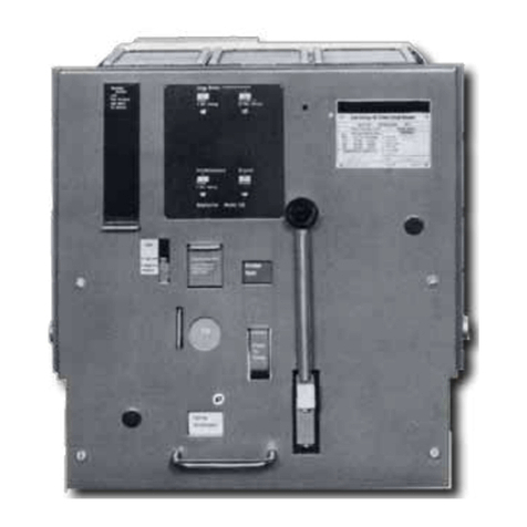
Instruction Book
Page vi Effective: March 2007
For more information visit: www.EatonElectrical.com I.B6513C80G
Page
4-1 MOC Drive Spring ..................................................................................................................................................13
4-2 Drive Spring Adjusted for 0 to 1 MOC Switch.....................................................................................................13
4-3 Drive Spring Adjustment Graphic ........................................................................................................................13
4-4 Checking Drive Spring for Proper Adjustment for One Installed Moc Switch ................................................13
4-5 Drive Spring Shown Adjusted for 2 MOC Switches ...........................................................................................14
4-6a Drive Spring Shown Adjusted for 3 MOC Switches ...........................................................................................14
4-6b 5 kV Drive Spring Adjusted for 3 MOC Switches ...............................................................................................14
4-7 MOC Pantograph Adjustment ...............................................................................................................................14
4-8 Snubber Adjustment ..............................................................................................................................................16
4-9 Positioning of 5 kV DHP-VR Breaker ...................................................................................................................17
4-10 Positioning of 7.5 or 15 kV DHP-VR Breaker ....................................................................................................18
4-11 Final Engagement of 5 kV Secondary Contact ...................................................................................................18
4-12 Final Engagement of 7.5 or 15 kV Secondary Contact ....................................................................................18
4-13 Levering 5 kV Breaker to Connected Position ...................................................................................................19
4-14 Levering 7.5 or 15 kV Breaker to Connected Position ......................................................................................19
5-1 DHP-VR 5 kV Interrupter Assembly .....................................................................................................................20
5-2 DHP-VR 7.5 or 15 kV Interrupter Assembly .......................................................................................................20
5-3 DHP-VR 5 kV Design - Front Faceplate Removed.............................................................................................23
5-4 DHP-VR 7.5 or 15 kV Design - Front Faceplate Removed ...............................................................................24
5-5 Closing Cam and Trip Linkage ............................................................................................................................25
5-6 Charging Schematic ..............................................................................................................................................26
5-7 Typical DHP-VR “DC”and “AC”Control Schemes ..............................................................................................28
5-8 Male Secondary Contact Block (In Extended Position) On 5 kV DHP-VR Breaker .......................................29
5-9 Male Secondary Contact Block (In Extended Position) On 15 kV DHP-VR Breaker .....................................29
5-10 Code Plate Installed On 5 kV DHP-VR Breaker .................................................................................................30
5-11 Code Plate Installed On 15 kV DHP-VR Breaker ..............................................................................................30
5-12 DHP-VR Breaker (5 kV) Floor Tripping Levers (Underneath Front View) ......................................................31
5-13 DHP-VR Breaker (7.5 or 15 kV) Floor Tripping Lever (Underneath Rear View) ............................................31
5-14 DHP-VR Breaker (5 kV) Rail Latch ......................................................................................................................31
5-15 DHP-VR Breaker (7.5 or 15 kV) Rail Latch .........................................................................................................31
5-16 DHP-VR Breaker Ground Contact ........................................................................................................................32
5-17 DHP-VR Breaker (5 kV) Levering-in Device Nut Housing ................................................................................33
5-18 DHP-VR Breaker (7.5 or 15 kV) Levering-in Device Nut Housing ..................................................................33
6-1 Lubrication Points ..................................................................................................................................................34
6-2 Vacuum Interrupter Showing Contact Erosion Indicator with Breaker Open .................................................37
6-3 Vacuum Interrupter Showing Contact Erosion Indicator with Breaker Closed ...............................................37
6-4 “T” Contact Wipe Indicator Example with Blue Spring .....................................................................................38
6-5 Wipe Indication Procedure ....................................................................................................................................38
6-6 Status Indicators.....................................................................................................................................................39
6-7 Starting Tape at Bottom of Cam ..........................................................................................................................39
6-8 Wrapping Tape up around Cam ..........................................................................................................................40
6-9 Attaching Tape around to Back of Cam ...............................................................................................................40
6-10 Attaching CloSureTM Test Tool at Hole “A” .........................................................................................................40
6-11 Attaching CloSureTM Test Tool at Hole “B” .........................................................................................................41
6-12 Manually Charging Closing Springs ....................................................................................................................41
6-13 Manually Closing Circuit Breaker with Marker in Hole “C” ................................................................................41
6-14 Top View of Cam and Marker Interface ...............................................................................................................41
6-15 Move Marker 15°to right ......................................................................................................................................41
6-16 Move Marker 15°to left ........................................................................................................................................42
6-17 Remove Marker Masking Tape from Cam ...........................................................................................................42
6-18 Place Tape on Right Side Panel of Breaker .......................................................................................................42
6-19 Illustrative Testing Tape Sample .........................................................................................................................42
6-20 Front View of CloSureTM Tool Showing Mounting/Testing Hole Locations ....................................................42
6-21 Typical Circuit Breaker Front View with CloSureTM Tool Attached .................................................................43
Courtesy of NationalSwitchgear.com
