3
INSTALLATION AND OPERATION MANUAL 25-16732-A November 2019 www.eaton.com
1. Introduction
1.1 Purpose
This manual is intended as a guide for the installation and
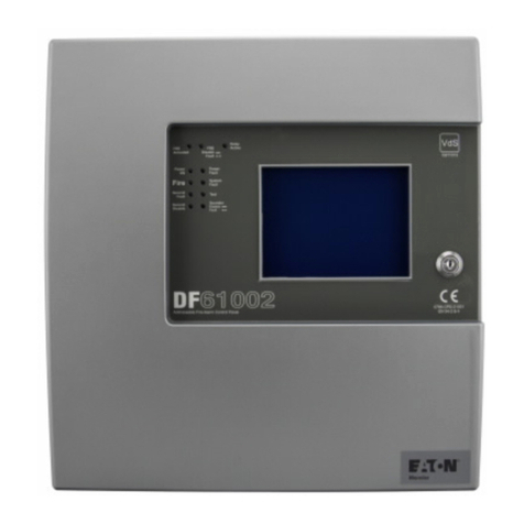
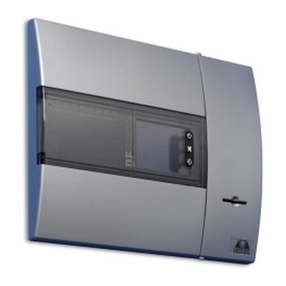
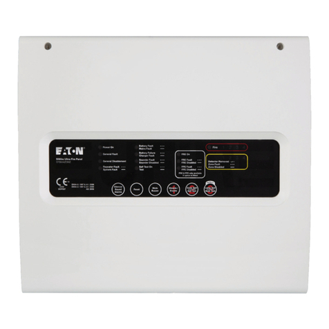
commissioning of the BiWire Flexi 2/4/8 Zone Control panel.
The content of this guide is intended to assist the user to
install a fire alarm system and does not specify the detailed
design of the product. The guide assumes a reasonable level of
competency with this type of system.
The installation of this system can only be carried out by
a competent person with relevant current training and
experience, with access to requisite tools, equipment and
information (as stipulated by BS5839).
The design has been carried out in accordance with a quality
management system, which incorporates a set of rules for the
design of all elements of the Control and Indication Equipment
(CIE) and Power Supply Equipment (PSE).
The components of the CIE and PSE have been selected for
the intended purpose, and are expected to operate within their
specification when the environmental conditions outside the
cabinet of the CIE / PSE comply with class 3k5 of
EN 60721-3-3:1995.
2. The BiWire Flexi Fire Detection
& Alarm System
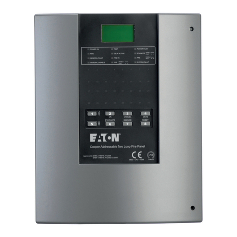
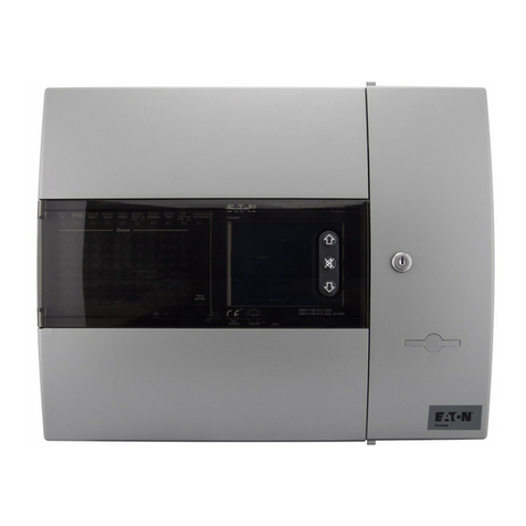
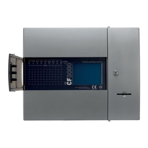
The BiWire Flexi fire alarm system is a highly adaptable
and intelligent product designed with the simplicity of
a conventional fire alarm system, enhanced to provide
multifunction fire detection and condition indication capability.
The Fire panel supports switchable zones that can be
configured for BiWire Mode that has detectors, call points,
sounders, and Visual Alarm Devices (VAD) combined on the
zone, or Conventional Mode (Standard or Intrinsically Safe
Mode) that only allows detectors and call points on the zone.
BiWire Mode eliminates the requirement to have separate
sounder circuits as with standard conventional systems, but
the BiWire Flexi also comes with conventional sounder circuits
to provide a purely conventional solution or a configurable
retro-fit solution.
The BiWire Flexi fire alarm system is certified to EN54 part 2
and part 4 and is designed to meet the recommendations in
BS5839.
The panels have the following optional features as standard:
• FIRE ALARM DEVICES: (EN54 part 2 clause 7.8)
• TEST CONDITION: (EN54 part 2 clause 10)
• Control of fire alarm routing equipment
(EN54 part 2 clause 7.9.1)
• Output to fire protection equipment
(EN54 part 2 clause 7.10.1)
The components of the BiWire Flexi Fire System are
as follows:
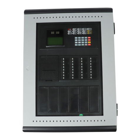
• The Fire Panel is available to support 2, 4 and 8 Detection
Zones. Each Zone, when set to BiWire operation, can be
configured with up to 32 input devices (including detectors
and manual call points) and 20 output devices connected via
a single 2-core screened cable.
• Depending on the type of Fire Panel, up to 2 conventional
sounder circuits can be used (see technical specifications
for loading characteristics). Each sounder circuit consists
of two sounder outputs. The total usable sounder outputs
depend on the BiWire or Conventional mode configuration
as outlined on page 11.
• The integrated EN54 part 4 compliant power supply charges
and monitors two 12V 5Ah batteries. The power supply is
capable of providing up to 24-hour standby depending on
the system loading (further information on this can be found
in the Technical information section of this document).
• When a zone is configured as BiWire mode, each zone must
be terminated with an intelligent end of line monitoring
module called the EOLM-3™. When a zone is configured for
Conventional mode, each zone must be terminated with an
EOLM-1 (for backward compatibility). Both EOLM modules
need to be located with the last device on the zone.
• The Fire alarm system has an options interface board to
provide outputs to Fire Protection Equipment (FPE), Fire
Routing Equipment (FRE) and zonal relays. This interface
and the relevant conformance requirements are further
described within this guide.
• The BiWire Flexi panel is only compatible with BiWire Ultra
range of devices for zones configured for BiWire mode,
and is also compatible with the standard Eaton range
of conventional devices on both conventional zones and
sounder circuits. When a conventional zone is configured
for Intrinsically Safe mode then intrinsically safe detectors
can be fitted in conjunction with an isolation barrier (see
technical specifications for more details).
