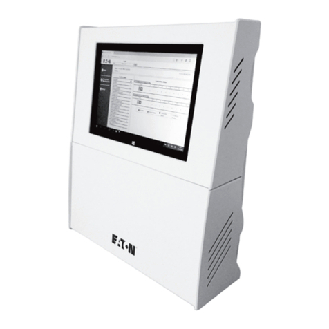
Eaton ELCM Series User manual
Other Eaton Controllers manuals
Eaton
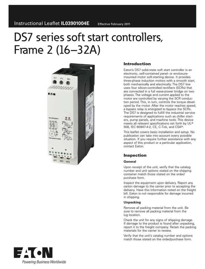
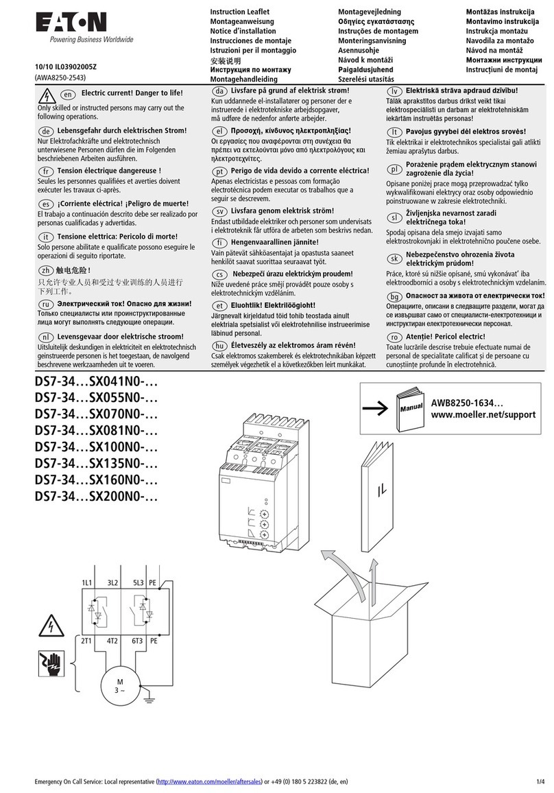
Eaton DS7-34 SX041N0 Series Manual
Eaton
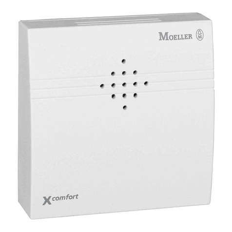
Eaton xComfort CJAU Series User manual
Eaton
Eaton xComfort CSAU-01/03 User manual
Eaton
Eaton Vickers SMC20 User manual
Eaton
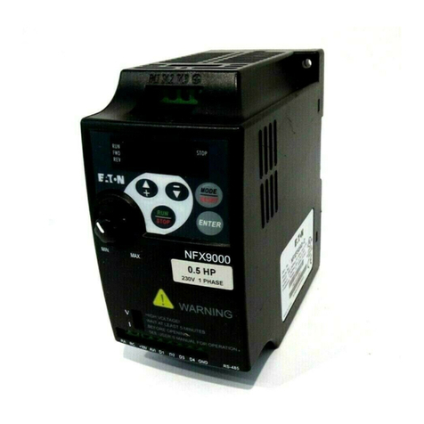
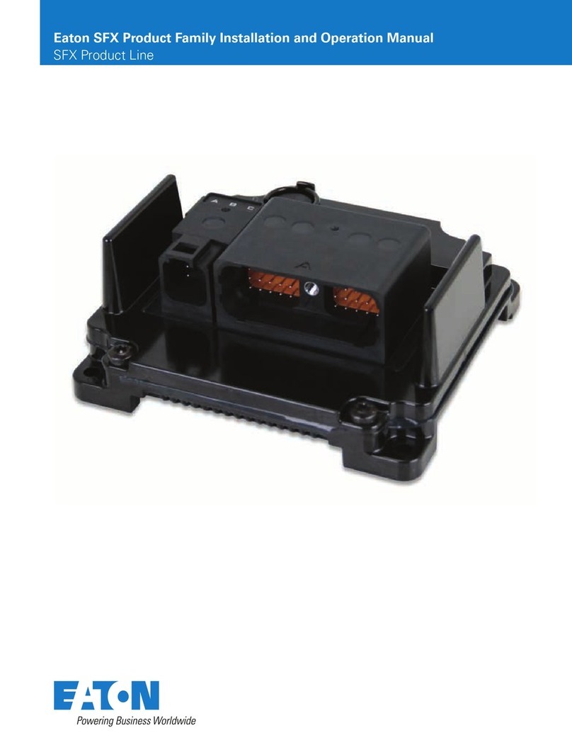
Eaton SFX Series User manual
Eaton
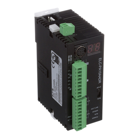
Eaton ELC-PA10AADR User manual
Eaton
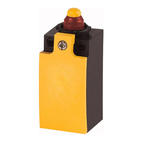
Eaton LS Series Manual
Eaton
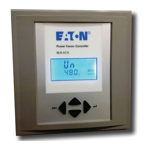
Eaton BLR-ACX User manual
Eaton
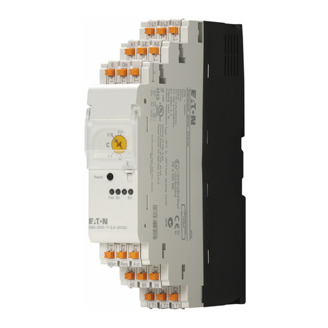
Eaton EMS 2,4 Series User manual
Eaton
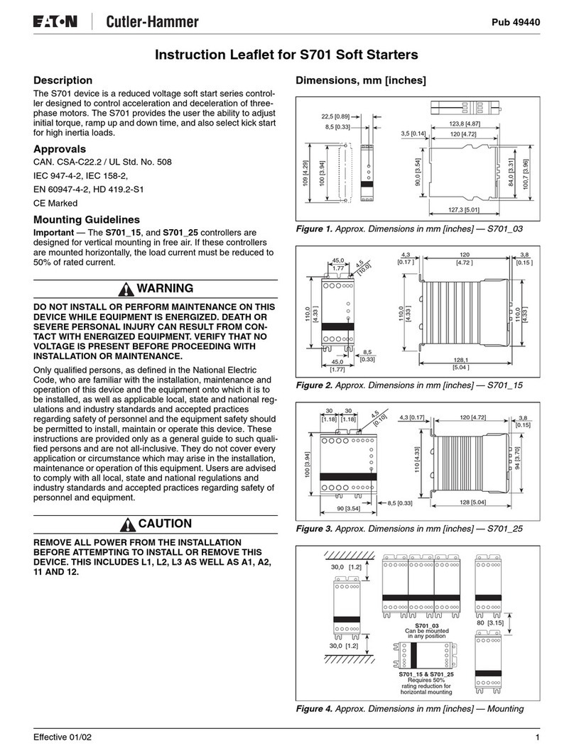
Eaton S701 Manual
Eaton
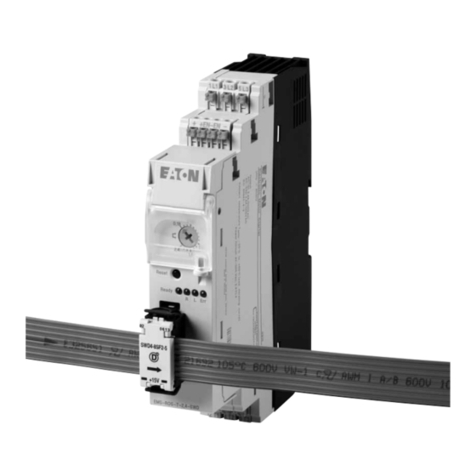
Eaton EMS-SWD Series User manual

Eaton
Eaton PowerXL DE1 series User manual
Eaton
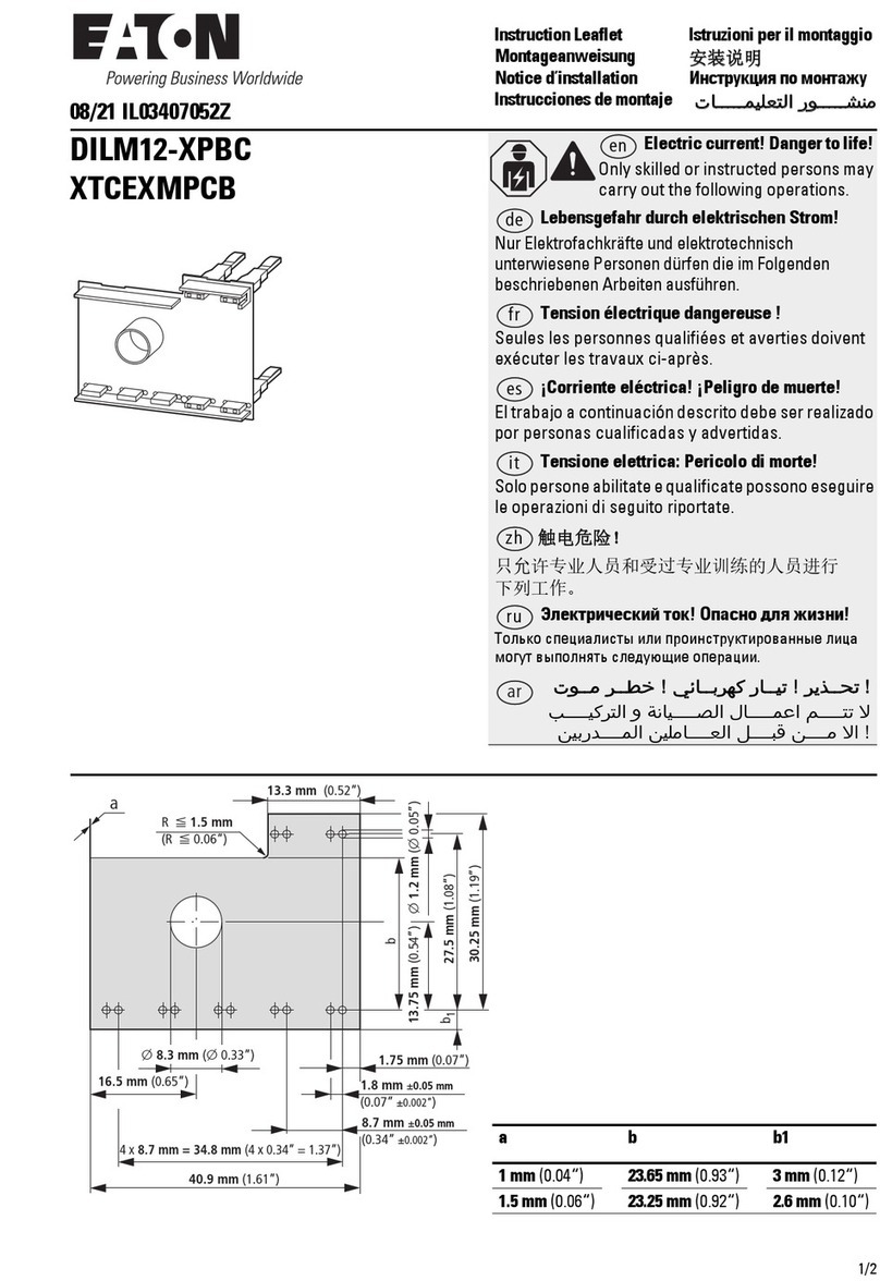
Eaton DILM12-XPBC Manual

Eaton
Eaton Crouse-hinds series User manual
Eaton
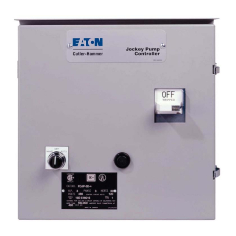
Eaton Cutler-Hammer Jockey User manual

Eaton
Eaton Ampgard 400 User manual

Eaton
Eaton Freedom 2100 Manual
Eaton
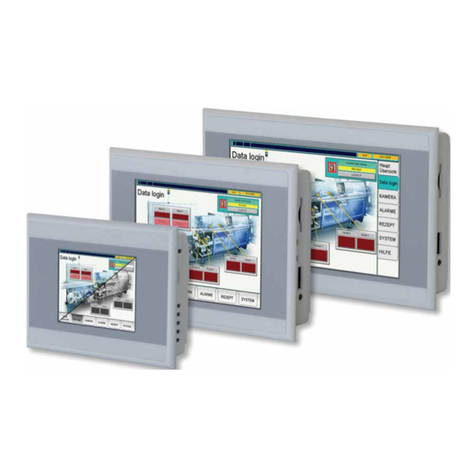
Eaton XV-102 Series User manual
Eaton
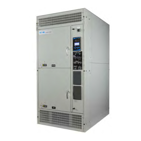
Eaton ATC-900 User manual
Eaton
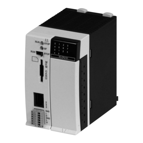
Eaton XC200 Series User manual
Popular Controllers manuals by other brands

Digiplex
Digiplex DGP-848 Programming guide

YASKAWA
YASKAWA SGM series user manual

Sinope
Sinope Calypso RM3500ZB installation guide

Isimet
Isimet DLA Series Style 2 Installation, Operations, Start-up and Maintenance Instructions

LSIS
LSIS sv-ip5a user manual

Airflow
Airflow Uno hab Installation and operating instructions
