2
Service Pullout
Installation
91712
NOTE: The Service Pullout is shipped with the Front
Legs in their uppermost position.
LEVELING THE SERVICE PULLOUT
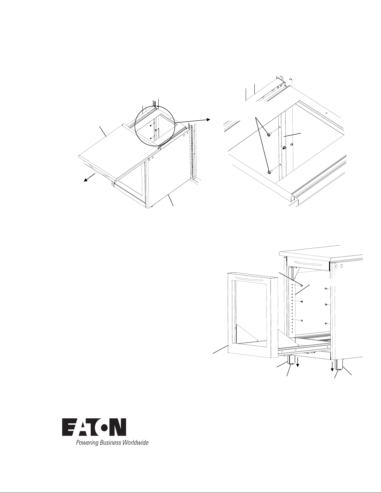
1. Pull the Drawer out. See figure 4.
2. Remove the three 1/4”-20 x 1/2” button head cap
screws that secure each Front Leg. Do not discard.
3. Drop the Front Legs down until the levelers touch the
floor. Move each leg up until the threaded holes in
the legs align with the nearest holes in the Front
Channels. Re-install the 1/4”-20 x 1/2” button head
cap screws and tighten securely.
4. Turn the levelers counter clockwise until they touch
the floor. Adjust the levelers to level the unit.
Figure 4
Drawer
Figure 3
1/4-20 x 1/2” hex
washer head screws
Hook Plate
1. Pull the top surface of the unit out to gain access to
the inside of the unit. Locate the two holes at the rear
corners of the Service Pullout and using a 3/8” socket
wrench, thread a 1/4”-20 x 1/2” hex washer head
screw into each hole. Tighten each screw securely .
See figure 3.
SECURING THE UNIT TO THE FRAME
IMPORTANT!
Top surface
Service Pullout
Leveler
1/4”-20 x 1/2” button
head screws
Leg
Leg
Leveler
Leg Channel
2
Service Pullout
Installation
91712
NOTE: The Service Pullout is shipped with the Front
Legs in their uppermost position.
LEVELING THE SERVICE PULLOUT
1. Pull the Drawer out. See figure 4.
2. Remove the three 1/4”-20 x 1/2” button head cap
screws that secure each Front Leg. Do not discard.
3. Drop the Front Legs down until the levelers touch the
floor. Move each leg up until the threaded holes in
the legs align with the nearest holes in the Front
Channels. Re-install the 1/4”-20 x 1/2” button head
cap screws and tighten securely.
4. Turn the levelers counter clockwise until they touch
the floor. Adjust the levelers to level the unit.
Figure 4
Drawer
Figure 3
1/4-20 x 1/2” hex
washer head screws
Hook Plate
1. Pull the top surface of the unit out to gain access to
the inside of the unit. Locate the two holes at the rear
corners of the Service Pullout and using a 3/8” socket
wrench, thread a 1/4”-20 x 1/2” hex washer head
screw into each hole. Tighten each screw securely .
See figure 3.
SECURING THE UNIT TO THE FRAME
IMPORTANT!
Top surface
Service Pullout
Leveler
1/4”-20 x 1/2” button
head screws
Leg
Leg
Leveler
Leg Channel
1∕4" - 20 x 1∕2" button
head screws
Securing the unit to the frame
1. Pull the top surface of the unit out to gain access
to the inside of the unit. Locate the two holes at
the rear corners of the Service Pullout and using
a 3∕8" socket wrench, thread a 1∕4" - 20 x 1∕2" hex
washer head screw into each hole. Tighten each
screw securely. See gure 3.
Leveling the service pullout
NOTE: The Service Pullout is shipped with the Front
Legs in their uppermost position.
1. Pull the Drawer out. See gure 4.
2. Remove the three 1∕4" - 20 x 1∕2" button head cap
screws that secure each Front Leg. Do not discard.
3. Drop the Front Legs down until the levelers touch
the oor. Move each leg up until the threaded holes
in the legs align with the nearest holes in the Front
Channels. Re-install the 1∕4" - 20 x 1∕2" button head cap
screws and tighten securely.
4. Turn the levelers counter clockwise until they touch
the oor. Adjust the levelers to level the unit.
Hook plate
Service pullout
Leg channel
Top surface
1∕4" - 20 x 1∕2" hex
washer head screws
Drawer
Leg
Leg
Leveler Leveler
Figure 3
Figure 4


