1.0 INTRODUCTION
Throughout this manual there are a number
of HAZARD WARNINGS that must be read
and adhered to in order to prevent possible
personal injury and/or damage to the equipment.
Three signal words "DANGER", "WARNING",
and "CAUTION" are used to indicate the
severity of the hazard, and are preceded by
the safety alert symbol .
Denotes the most serious hazard,
and is used when serious injury or
death WILL result from misuse or
failure to follow specific instructions.
When serious injury or death
MAY result from misuse or failure to
follow specific instructions.
When injury or product/equipment
damage may result from misuse or
failure to follow specific instructions.
It is the responsibility and the duty of all
personnel involved in the installation, opera-
tion and maintenance of the equiment on
which this device is used to fully understand
the , and
procedures by which hazards are to be
avoided.
1.1 Description
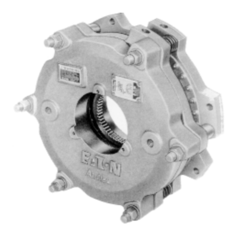
1.1.1 The Airflex Model DBB brakes were
designed for heavy duty industrial
applications where spring set (power off)
braking is required.
1.1.2 All Airflex DBB brakes are supplied with long
wearing, NON-ASBESTOS friction material.
1.1.3 The spring housing (16) piston and cylinder
(19) are Nituff®coated, which is Teflon pene-
trated hard coat anodizing. The friction disc
assembly (101) is made out of steel and is
specially nitrided with a quench-polish-
quench system. The release springs (34) are
made from stainless steel and have flexible
polyurethane coating. The exposed cast sur-
faces are painted with multiple coats of
corrosion resistant paint. Bronze bushings
are provided in the reaction plate and pres-
sure plates to facilitate axial movement. The
clamp tubes (12) are made from aluminum-
bronze which provides high resistance to
wear and corrosion.
1.1.4 The rugged construction ensures long,
trouble free service. The corrosion protection
provided with these units will help prevent
premature failure when using in marine
environments. The iron components are
painted with a marine,two coat, epoxy coat-
ing. All other components are either coated
or manufactured with corrosion resistant
alloys.
1.2 How it Works
1.2.1 Referring to Figure 1, the gear (28) is
mounted on the shaft which is to be stopped
and the brake assembly is attached to the
machine frame or a reaction bracket. As air
pressure is applied through the ports in the
cylinder (19), the cylinder and pressure plate
(13), which are attached to each other with
screws (20), flat washers (17) and spacer
tubes (27), move away from the mounting
flange (1), which is connected to the
machine frame or reaction bracket. The
pressure plate compresses the springs (22)
against the stationary spring housing (16)
and the clamp force is removed from the
friction disc assembly (7) which rides on the
gear. The shaft is then free to rotate. As air
pressure is exhausted, the springs force the
pressure plate toward the mounting flange,
clamping the friction disc assembly between
the two members. On dual disc models, an
additional friction disc assembly and a
reaction plate (30) are clamped between the
pressure plate and mounting flange.
DBB8104 PDFformat 2© Copyright Eaton Corp., 1998. All rights reserved.
(Revised:January,1998)
