3
INM9107 Rev 2
2.2 Module carrier
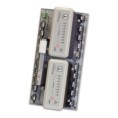
The module carrier provides fieldbus power for four fieldbus segments. It supports pluggable power
supply and arbitration modules for each segment and all connection facilities.
Each carrier has pluggable screw terminal connections for redundant 24V input power and for the
intrinsically safe field trunks. The screw terminal, host fieldbus segment connectors are provided as
pairs to enable individual connections of separate redundant host H1 systems. A volt-free failure alarm
is also provided for connection to a digital input module. There are no active electronic circuits on the
carrier, resulting in long calculated Mean Time To Failure (MTTF) and overall high system availability.
The carrier dimensions (Figure 2.2) are designed to provide high packing density in typical 800mm
wide equipment cabinets. Survival in high-vibration marine environments is achieved by secure
panel-mount fixings.
The FISCO power supply modules are pluggable versions of the MTL 9122-IS range, and support
the same level of features. LED indicators provide information on system health and assist with fault
diagnosis.
3 INSTALLATION
WARNING!
This equipment must be installed, operated and maintained only by trained competent
personnel and in accordance with all appropriate international, national and local standard
codes of practice and site regulation for intrinsically safe apparatus and in accordance with the
instructions contained here.
3.1 General
The 9107-22 power system is designed for mounting in a non-hazardous area.
The mounting conditions must:
a. prevent any form of pollution that could compromise the operation of the unit. For example, an
unpolluted location or a suitable enclosure could be chosen.
b. provide an adequate level of mechanical protection. This can be achieved by selecting a
protected location, a suitable cabinet or enclosure, or a combination of both.
c. ensure that all cable entries and connections are secure by making provision for the careful
routing and securing of all cables.
d. provide adequate security against unauthorised interference.
e. ensure that the permitted ambient temperature range of the units (–20°C to + 60°C) is not
exceeded. Be aware of the power dissipation in the equipment’s cabinet or enclosure and
consider the use of shading against direct sunlight, or even forced cooling.
3.2 Required tools
To remove or replace a FISCO or a SAM module a straight-bladed screwdriver is required with a
minimum shaft length of 130mm (5¼”) and a maximum blade diameter of 5mm (3/16”).
3.3 Mounting overview
Mount the 9107-22 assembly on a vertical surface with the orientation shown in Figure 2.2. Any
other orientation will reduce the permitted maximum operating temperature.
IMPORTANT: The mounting surface and any fixings must be capable of supporting the weight of
the complete assembly which is approximately 6.4kg.
Four 7mm diameter slotted holes are provided in the backplate for mounting the assembly - see
Figure 3.1 - and access to the mounting screws is provided through the circuit board (after removal
of some modules). This feature allows the assembly to be fitted to, or removed from, its mounting
without removing the mounting screws.
Note that because of the slotted mounting holes, 15mm of free space is required above the top
edge of the assembly to allow the backplate to be mounted and demounted.
3.3.1 Outdoor mounting
If the assembly is to be mounted in an outdoor location, a suitable enclosure with a minimum of IP54
ingress protection is required. However, in some locations, a higher degree of ingress protection rating is
recommended as corrosion resistance may be necessary or desirable and the emphasis should be placed
on the suitability for the application.


