manuals.online logo
Brands
  1. Home
  2. •
  3. Brands
  4. •
  5. Eaton
  6. •
  7. Relay
  8. •
  9. Eaton EMR4-RAC-1-A Manual

Eaton EMR4-RAC-1-A Manual

Other Eaton Relay manuals

Eaton EAFR-101C User manual

Eaton

Eaton EAFR-101C User manual

Eaton C440/XTOE User manual

Eaton

Eaton C440/XTOE User manual

Eaton ESR5-BWS-31-24VAC-DC User manual

Eaton

Eaton ESR5-BWS-31-24VAC-DC User manual

Eaton Cutler-Hammer D64RPB30 Series User manual

Eaton

Eaton Cutler-Hammer D64RPB30 Series User manual

Eaton Cooper Power Systems RLY-800 Manual

Eaton

Eaton Cooper Power Systems RLY-800 Manual

Eaton Cutler-Hammer D64RPB100 Series User manual

Eaton

Eaton Cutler-Hammer D64RPB100 Series User manual

Eaton EMT62-DB Manual

Eaton

Eaton EMT62-DB Manual

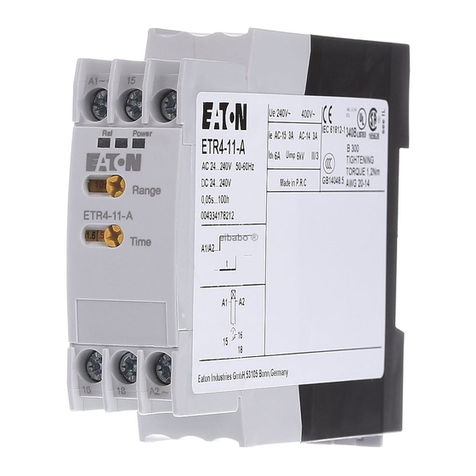
Eaton ETR4-11-AB Manual

Eaton

Eaton ETR4-11-AB Manual

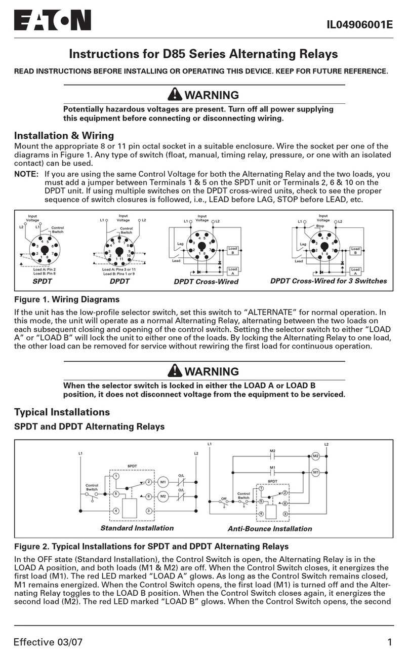
Eaton D85 Series User manual

Eaton

Eaton D85 Series User manual

Eaton E Series User manual

Eaton

Eaton E Series User manual

Eaton EMR5-AWN500-1 User manual

Eaton

Eaton EMR5-AWN500-1 User manual

Eaton ZB150 Series Manual

Eaton

Eaton ZB150 Series Manual

Eaton ESR5-NO-31-230VAC User manual

Eaton

Eaton ESR5-NO-31-230VAC User manual

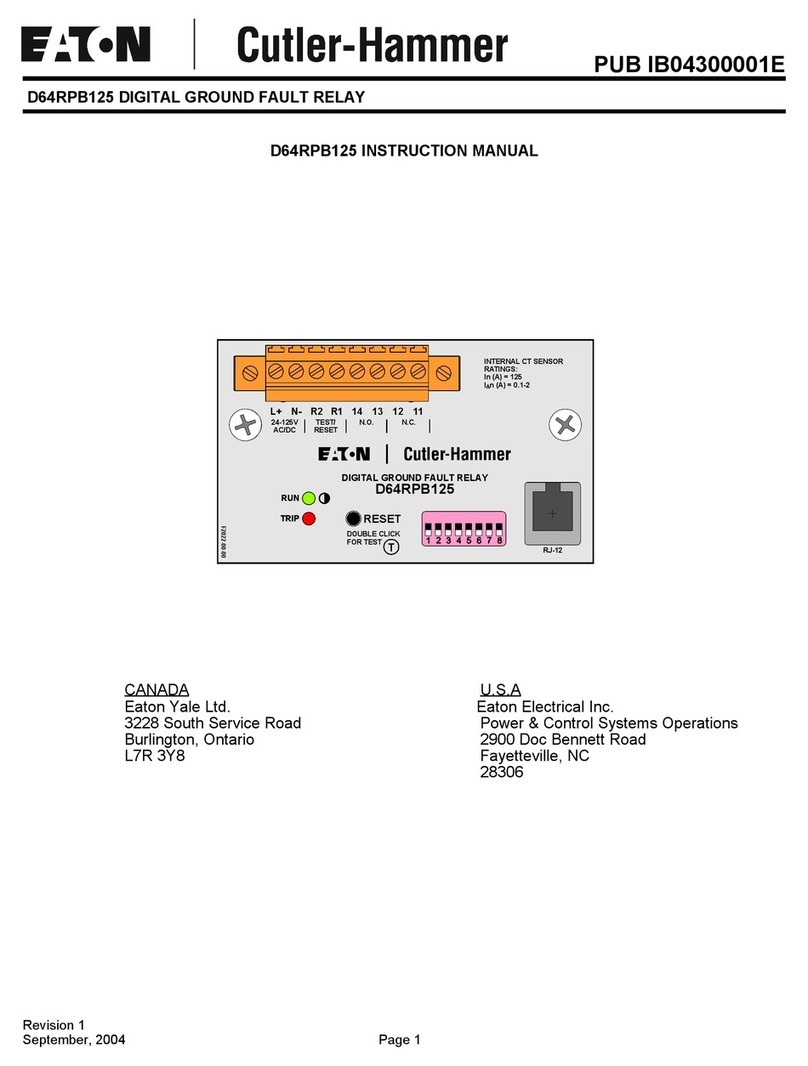
Eaton Cutler-Hammer D64RPB125 User manual

Eaton

Eaton Cutler-Hammer D64RPB125 User manual

Eaton Cutler-Hammer D64RP14 Series User manual

Eaton

Eaton Cutler-Hammer D64RP14 Series User manual

Eaton EMT6-K Manual

Eaton

Eaton EMT6-K Manual

Eaton E Series User manual

Eaton

Eaton E Series User manual

Eaton Moeller ZEV Series Service manual

Eaton

Eaton Moeller ZEV Series Service manual

Eaton AA13P Manual

Eaton

Eaton AA13P Manual

Eaton 473-N Manual

Eaton

Eaton 473-N Manual

Eaton PKE-XZMR Series Manual

Eaton

Eaton PKE-XZMR Series Manual

Eaton Power Xpert C445 User manual

Eaton

Eaton Power Xpert C445 User manual

Eaton EDR-5000 Installation and operating instructions

Eaton

Eaton EDR-5000 Installation and operating instructions

Eaton ETR4-70-A Manual

Eaton

Eaton ETR4-70-A Manual

Popular Relay manuals by other brands

Woodward BU1-DC2 manual

Woodward

Woodward BU1-DC2 manual

ABB SSR32 product manual

ABB

ABB SSR32 product manual

Siemens SIRIUS 3UG4633 operating instructions

Siemens

Siemens SIRIUS 3UG4633 operating instructions

Siemens SIRIUS 3TK2824 A.20 Series Original operating instructions

Siemens

Siemens SIRIUS 3TK2824 A.20 Series Original operating instructions

Shelly Pro Series user manual

Shelly

Shelly Pro Series user manual

GE MVAX 11 Technical manual

GE

GE MVAX 11 Technical manual

ABB RELION REF615R manual

ABB

ABB RELION REF615R manual

Kemo Electronic B197 quick guide

Kemo Electronic

Kemo Electronic B197 quick guide

Seg MRM3 manual

Seg

Seg MRM3 manual

Basler BE1-700C manual

Basler

Basler BE1-700C manual

CD Automation REVEX 2PH 280A user manual

CD Automation

CD Automation REVEX 2PH 280A user manual

ABB SPAJ 142 C User manual and technical description

ABB

ABB SPAJ 142 C User manual and technical description

Ruelco 1S04 Operation manual

Ruelco

Ruelco 1S04 Operation manual

Basler V3E Z1P B2C1F instruction manual

Basler

Basler V3E Z1P B2C1F instruction manual

GE DGP instruction manual

GE

GE DGP instruction manual

Kyongbo Electronics GDR-D01 user manual

Kyongbo Electronics

Kyongbo Electronics GDR-D01 user manual

Siemens BD2-AK03X/FS Series installation instructions

Siemens

Siemens BD2-AK03X/FS Series installation instructions

Leuze MSI-SR5B Original operating instructions

Leuze

Leuze MSI-SR5B Original operating instructions

manuals.online logo
manuals.online logoBrands
  • About & Mission
  • Contact us
  • Privacy Policy
  • Terms and Conditions

Copyright 2025 Manuals.Online. All Rights Reserved.

Electric current! Danger to life!
Only skilled or instructed persons may carry out the
following operations.
Lebensgefahr durch elektrischen Strom!
Nur Elektrofachkräfte und elektrotechnisch unterwiesene
Personen dürfendie im Folgenden beschriebenen Arbeiten
ausführen.
Tension électrique dangereuse!
Seules les personnes qualifiées et averties doivent
exécuter les travaux ci-après.
¡Corriente eléctrica! ¡Peligro de muerte!
El trabajo a continuación descritodebe ser realizadopor
personas cualificadas yadvertidas.
Tensione elettrica: Pericolo di morte!
Solo persone abilitate e qualificate possono eseguire le
operazioni di seguito riportate.
en
de
fr
es
it
Emergency On Call Service:Localrepresentative (http://www.eaton.com/moeller/aftersales) or +49 (0) 180 5 223822 (de, en)1/3
Instruction Leaflet
Montageanweisung
Notice d’installation
Instrucciones de montaje
Istruzioni per il montaggio
06/11 IL04912002Z
(AWA2433-1866)
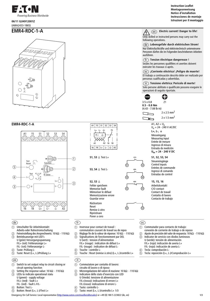
EMR4-RAC-1-A
EMR4-RAC-1-A
S1 Eq
Externer Test
External test
Test externe
Testo esterno
Prueba externa
S1, S2 q
Fehler speichern
Memorise fault
Mémoriser le défaut
Memorizzazione errore
Guardar error
Rücksetzen
Reset
Remise à zéro
Ripristinare
Poner a cero
a
Einstellung des Widerstandsbereichs:
11 kOoder 110 kO
b
Feineinstellungdes Ansprechwertes:
1-11 kOoder11 - 110 kO
c
Betriebsanzeige mitLED´s
FLED rot: Fehleranzeige
(Erdschlusswiderstand<Ansprechwert)
U LEDgrün: Versorgungsspannung
d
Reset/Prüftaste
a
Réglagede la résistance sur : 11 kOou 110 kO
b
Réglage de précision de la valeur d´activation :
1-11 kOou 11 - 110 kO
c
Indicateur de fonctionnement avec DEL
F DEL rouge : Affichage des anomalies
(valeur d´activation de la résistancede
court-circuit àla terre)
U DEL verte : tension d´alimentation
d
Reset/touche de controle
a
Ajustedel margen de resistencias: 11 kOó110 kO
b
Ajuste de precisión de la sensibilidad mínima de reacción:
1-11 kOó 11 - 110 kO
c
Indicador de servicio con LEDs
d
FLEDrojo: Indicador de interrupción
(resistencia de contacto atierra,
sensibilidad mínima de reacción)
e
U LED verde: Tensión de alimentación
f
Reset/Tecla de prueba
a
Adjustment of the resistance range:
11 kOor 110 kO
b
Fine adjustment of the response factor:
1-11 kOor 11 - 110 kO
c
Operating displaywith LED´s
FLED red: Error display
(ground leakage resistance response factor)
U LEDgeen: Power supplyvoltage
d
Reset/Test button
a
Impostazione del campo di resistenza: 11 kOo110 kO
b
Regolazione di precisione del valore di attivazione:
1-11 kOo 11 - 110 kO
c
DisplayaLED
(U (verde): tensione di alimentazione
LED F (rosso): indicazione di errore
(resistenzadi terra < valore di attivazione)
LEDU (verde): tensione di alimentazione
d
Reset/pulsante di test
3.5 x 0.8
0.5 - 0.8 Nm
(4.43 - 7.08 lb-in)
Z1
2x2.5 mm2
2x1.5 mm2
A1, A2
S1,S2 E
15, 16, 18
L, E
Variante mit Versorgungsspannung
24 - 240 V AC/DC
Steuereingänge
Arbeitskontakt
Messeingang
A1, A2
S1,S2 E
15, 16, 18
L, E
Variant with power supply voltage
24 - 240 V AC/DC
Control inputs
Operating contact
Measurement point
A1, A2
S1,S2 E
15, 16, 18
L, E
Variante avec tension d´alimentation
24 - 240 V AC/DC
Entrées de commande
Contact de travail
Entrée de mesure
A1, A2
S1,S2 E
15, 16, 18
L, E
Variante con tensione di alimentazione
24 - 240 V AC/DC
Ingressi di comando
Contatto di lavoro
Ingresso di misura
A1, A2
S1,S2 E
15, 16, 18
L, E
Variante con tensión de alimentación
24 - 240 V AC/DC
Entradas de control
Contacto de trabajo
Entrada de medición
5
6
7
U
Sector
110k
R–value
Test
Reset
A1 15 S1 S2
16 18 LA2
F
A1
15
A2
16
18
a
d
c
b
A1 15 S1 S2
16 18 LA2
15
L
R <
1816A1 A2
S1
S1 S2
S1 S2
de fr it
en es
2/3Emergency On Call Service: Local representative (http://www.eaton.com/moeller/aftersales) or +49(0) 180 5223822 (de, en)
06/11 IL04912002Z
Gefahr!
Das EMR4-RAC-1-A ist für reine Wechselspannungsnetze konzipiert, parallel geschaltete Gleichstromkreise führen zuFehlern bzw. falschen Reaktionen.
Das EMR4-RAC-1-A erfüllt die Anforderungen nach VDE0413/T2.
Danger!
The EMR4-RAC-1-A is designed for pure alternating current networks, while parallel-switched direct currentcircuits lead to faults as well as to false reactions.
The EMR4-RAC-1-A fulfills the requirements of VDE0413/T2.
Danger!
L‘EMR4-RAC-1-A est exclusivement conçu pour des secteurs à tension alternative, les circuits de courantcontinu montés parallèlement se traduisant par desdéfauts et
des réactions incorrectes. L’ EMR4-RAC-1-A est conforme à VDE 0413/T2.
Pericolo!
L’apparecchio EMR4-RAC-1-A è stato concepito per retia corrente alternata pure; circuiti acorrente continuacollegati in parallelo causano errori ovvero reazionierrate.
L’apparecchio soddisfa i requisiti dettati dallenorme VDE 0413/T2.
¡Advertencia!
El EMR4-RAC-1-A ha sido concebido para redes detensión alterna pura; circuitos de corriente continuaconectados en paralelo conducen a que se produzcanerrores,
o bien, reaccionens erróneas. El EMR4-RAC-1-A satisface los requerimientosimpuestots según VDE 0413/T2.
aVersorgungsspannung
bFernanschluss – Speichern,Rücksetzen
cFrontseitige Taste Test/Reset – Rücksetzen, Prüfen
Fernanschluss S 1/E– Rücksetzen, Prüfen
dIsolationswiderstand R des Netzes
EingestellterAnsprechwert – Rx
eArbeitskontakt
tT= tTest > ca. 300 ms
aPower supply voltage
bRemote connection –Store, Restore
cFront panel button – Reset, Test
Remote connection S1/E– Reset/Test
dIsolation resistance R of thenetwork
Adjusted response factor – Rx
eOperating contact
tT= tTest > approx. 300 ms
aTension d’alimentation
bTélé-raccord – sauvegarder, remise à zéro
cTouche avant–remise à zéro, contrôler
Télé-raccord S 1/E– remise à zéro, contrôler
dRésistanced’isolement R du secteur
Valeur d’activation ajustée – Rx
eContact de travail
tT= tTest > ca. 300 ms env.
aTensione di alimentazione
bCollegamento a distanza – memorizzazione, reset
cPulsante frontale di test/reset
Collegamento a distanzaS1/E– reset, test
dResistenza di isolamento R della rete
Valore di attivazione impostato – Rx
eContatto di lavoro
tT= tTest > circa. 300 ms
aTensión de alimentación
bTeleconexión – almacenamiento, reposición
cTecla frontal – reposición, control
Teleconexión S 1/E– reposición control
dResistencia de aislamiento R de la red.
Sensibilidad mínima de reacción ajustada – Rx
eContacto de trabajo
tT= tTest > approx. 300 ms
de
en
fr
it
es
R
1.6 x Rx
tT
aA1/A2
cTest
Reset
bS3/S1
d
S1E
e15/18
15/16
hEMR4-RAC-1-A wirdzur Isolationsüberwachung von ungeerdeten Wechselspannungsnetzen mit
1oder 3 Phasen eingesetzt. Überwacht wird der Isolationswiderstand des Netzes gegen denSchutzleiter.
Die Messung erfolgt mittels einer dem Wechselspannungsnetz überlagerten Gleichspannung.
Messkreis und Versorgungskreis können identischsein.
hThe EMR4-RAC-1-A is used for monitoring the isolation of ungrounded1or 3 phase alternating current
networks. The isolation resistance between the network and the protective conductor is monitored.
The measurement is made by means of a directcurrent superimposed on the alternating current
network. The measurement circuit and the power supply circuit may be identical.
The reaction timeis hereby dependent on the value of the resistance difference.
hL‘EMR4-RAC-1-A est utilisé pour surveiller l’isolement de secteurs à tension alternative sans protection
de terre avec 1 ou 3 phases. La surveillance concerne la résistance d’isolement du secteur par rapport
au filde protection. La mesure a lieu au moyen d’une tension continue superposant le secteur de tension
alternative. Le circuit de mesure et le circuitd’alimentation peuventêtre identiques.
La durée de réaction dépend alors de la différence entre les résistances.
hL’apparecchio EMR4-RAC-1-A viene impiegatoper la sorveglianza dell’isolamento in reti a corrente
alternata monofase o trifase senza collegamento a terra. Viene sorvegliata la resistenza di isolamento
della rete rispetto il conduttore di protezione. La misura avviene tramite una tensione continua
sovrapposta allatensione alternata della rete.
Il circuito di misura ed il circuito di alimentazione possono essere identici.
hEl EMR4-RAC-1-A se utiliza para la supervisión del aislamiento de redes no puestas a tierra de tensión
alterna,con una o dos fases. Lo que se controla es la resistencia de aislamiento de la red respecto al
conductor de protección. La medición se efectúa mediante una tensión continua superpuesta a la red de
corriente alterna. El circuito de medición y el circuito de alimentación pueden seridénticos.
En este caso, el tiempo de reacción es una función del valor absoluto de la differencia de resistencias.
de
en
fr
it
es
Emergency On Call Service:Localrepresentative (http://www.eaton.com/moeller/aftersales) or +49 (0)180 5223822 (de, en)3/3
06/11 IL04912002Z
Eaton Industries GmbH, Hein-Moeller-Straße 7-11, 53115 Bonn, Germany
©2000 by Eaton Industries GmbH, www.eaton.com/moeller/support All Rights Reserved
06/11 IL04912002Z 4.459.072.11 Doku
Printed in Germany (06/11)
a
min.Einstellwert fR/3 + gewünschter Schwellwert
b
künstl. Nullleiter
a
Min. setting value fR/3 +required threshold
b
Artificial zero conductor
a
Valeur de réglage min. fR/3+ valeur seuil souhaitée
b
Neutre artificiel
a
Valore di impostazione min. fR/3 + valore di attivazione desiderato
b
Messa aterra
a
Valorde respuestamínimo fR/3+valor de umbral deseado
b
Conductor neutro artificial
aLöschtaste
bPrüftaste
aDelete button
bTest button
aTouche d’effacement
bTouche d’essai
aTasto di cancellazione
bTasto di verifica
aTecla de borrado
bTecla de prueba
Ansprechverzögerung in Abhängigkeit des
Isolationswiderstandes bei schneller Änderung
td=0 s und des eingestellten Ansprechwertes
On-delay depending on the isolation resistance
with small change in td= 0 s and set threshold
value
Retard à l’appel en fonction de la résistance
d’isolement en cas de changement rapide de
td=0 s et de la valeur d’appel de réglage
Ritardo all’inserzione in base allaresistenza di
isolamento con modifica rapida td= 0 s del
valore di eccitazione impostato
Temporización de trabajo dependiendo de la
resistencia de aislamiento concambio rápido
td=0 s y del valor de respuesta establecido
tA= Verzögerungszeit
Rim= Gemessener Isolationswiderstand
Ris=Eingestellter Isolationswiderstand
tA= Delay time
Rim= Measured isolation resistance
Ris= Set isolation resistance
tA=Temporisation
Rim=Résistance d’isolement mesurée
Ris= Résistance d’isolement réglée
tA=Tempo di ritardo
Rim=Resistenza d’isolamento misurata
Ris= Resistenza d’isolamento impostata
tA=Tiempo de retardo
Rim= Resistencia de aislamiento medido
Ris= Resistencia de aislamiento
establecido
A1
A2
L
L2
220 – 415 V L1
L3
~EMR4-
RAC...
N
A1
A2
L
L1
110 – 240 V, 1~
N
~EMR4-
RAC...
A1
A2
L
L2
380 – 415 V L1
L3
*380 V: R = 68 kΩ (5 W)
400 V: R = 75 kΩ (5 W)
415 V: R = 82 kΩ (5 W)
~
a
b
EMR4-
RAC...
A1
A2
L
L2
220 – 240 V L1
L3
~EMR4-
RAC...
A1 15 S1 S2
16 18 LA2
15
L
R <
1816A1 A2
ab
L
N
PE
A1 15 S1 S2
16 18 LA2
15
L
R <
1816A1 A2
ab
L2
L1
L3
N
3
2.5
2
1.5
1
0.5
0.1 1 10 100
[sec]
[kO]
1001246 10 20 40 60 [kO]
Rim
RiS
tA
109.5 mm (4.31”)
102 mm (4.02”)
78mm (3.07”)
5.5 mm (0.22”)
1 mm (0.04”)
100 mm (3.94”)
45 mm (1.77”)