manuals.online logo
Brands
  1. Home
  2. •
  3. Brands
  4. •
  5. Eaton
  6. •
  7. Remote Control
  8. •
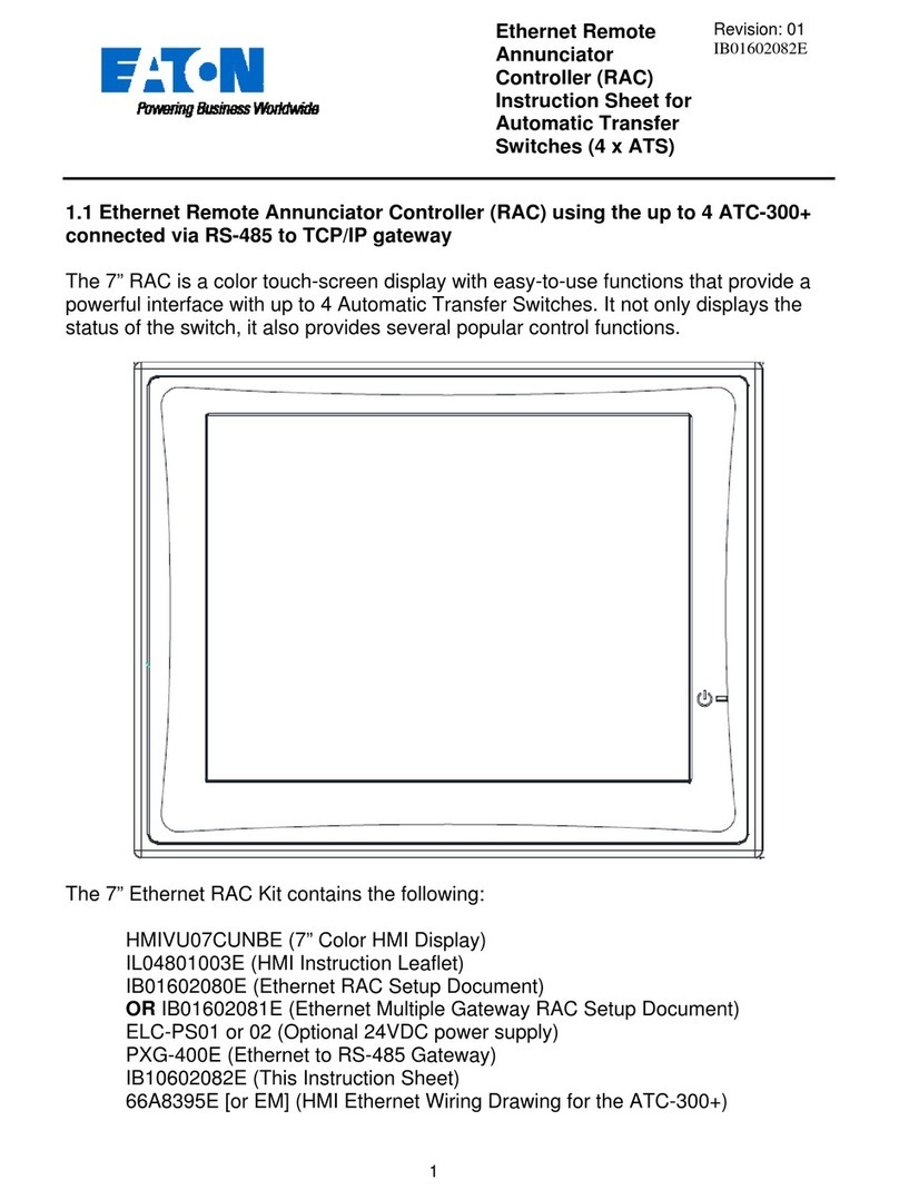
  9. Eaton HMIVU07CUNBE User manual

Eaton HMIVU07CUNBE User manual

1
Remote Annunciator
Controller (RAC)
Instruction Sheet for
ATC-900 Controllers
Revision: 006
IB140010EN
Overview1.0
The 7” RAC is a color touch-screen display with easy-to-use functionsthat provide a
powerful interface with up to 8 Automatic Transfer Switches equipped with the ATC-
900 controller. It supports serial RS-485 Modbus RTU and Modbus TCP/IPnatively.
When using Ethernet to connect to an ATC-900, a serial-to-Ethernet Modbus gateway
is required such as the PXG-900 or the ELC-CAENET.
The 7” RAC Kit contains the following:
HMIVU07CUNBE (7” Color HMI Display)
IL04801003E (HMI Instruction Leaflet)
IB01602080E (Ethernet Setup Document)
ELC-PS01 or 02 (Optional 24VDC power supply)
IB140010EN (This Instruction Sheet)
66A8395, E, or EM (HMI Wiring Diagram)
66A8448H02 (HMI Interconnect Module– serial connections only)
2
Features2.0
There are three types of features incorporated into the ATC-900 RAC: Status, Control,
and Setpoint Editing.
Status Indicators
S1 / S2 AvailableS1 / S2 PreferredS1 / S2 ConnectedS1 / S2 Status (Under/Over Voltage, Under/Over Frequency, etc.)Emergency InhibitLockout / Monitor ModeClosed on EmergencyGo to Emergency ActiveEngine Test ActiveTransfer in ProgressSource 1 Voltage MeteringSource 2 Voltage MeteringLoad Voltage Metering (includes Current if DCT module is installed)Waiting for Manual RetransferHistory of EventsActive Timer
Control Pushbuttons
Go to Emergency / Cancel Go to EmergencyStart / Stop Engine TestAlarm SilenceRemote Alarm ResetBypass TimersManual Retransfer
Setup and Wiring3.0
The RAC requires 24VDC power with aminimum current of 360 mA (See “A” below).
There is a terminal block connector on the back of the unit to install wires for the
power. The software comes preloaded onto the unit according to your switch
configuration, and should require no user programming.
The RAC supports Modbus RTU (serial RS-485) and Modbus TCP/IP (Ethernet).
However, since the ATC-900 controller only supports serial Modbus, an RS-485 serial-
to-Ethernet gateway must be used for Modbus TCP/IP. Eaton recommends using the
ELC-CAENET module or a Power Xpert Gateway (PXG-900).
Drawing 66A8395 shows the wiring of the unit over serial Modbus. Consult drawing
66A8395E (or EM) when using Ethernet gateways. All RS-485serial cable must have
three insulated conductors (D0, D1, COM) and one ground(drain) connected to the
shielding of the cable. The Eaton recommended cable is Belden 3106A. Ethernet
cable may be any CAT5/6 certified cable.
3
Note: multiple Modbus Ethernet gateways may be used to further expand the
communication flexibility of the system. Drawing 66A8395EM should be referenced for
wiring of multiple gateways.
ATC-900 Setup3.1
The communication setpoints on each ATC-900 need to be set as follows:
Baud Rate: 9600, 1-stop, Even
Address: 01, 02, 03, 04, 05, 06, 07 or 08 (each ATC-900 must be unique)
ELC-CAENETEthernet Gateway
PXG-900 Ethernet Gateway
4
Termination SW1: Normally OFF. Should be ON for last controller in the
chain only if using a 120 Ohm resistor on the opposite end of a communication
daisy-chain.
RAC Setup3.2
Your HMI is factory set with communications disabled for all controllers, and
must be enabled during startup. To enable communications, press on any disabled
controller from the Overview screen (or the “System Setup” button on the Controller
screen if you have a single-view HMI). Enter yourpassword (default of 0900). A list of
available controller com links will appear. To name a controller, press the“Edit” button
next to the corresponding controller. To enable communications toa controller, press
the red “Disabled” button under the Coms column; it will change green and display
“Enabled”. To disable communicationsto a controller, press the green “Enabled”
button; it will change back red and display “Disabled”. More detail can be seen in
section 4.0 below.
To change your ATC-900 Setpoints, simply press the orange“Edit ATC # Setpoints”
button, and you will be taken to the first setpoint screen. See section4.6 for more
details.
You can also change items like HMI touch screen force, touch screen calibration, time
& date, brightness & contrast, alarm & touch volume, and others. To do this, you have
two options:
The first is to simply press the small SYSTEM button on theback of the unit for two
seconds. The system menu will now be displayed on the screen. The menus are self-
explanatory but if additional help is required, consult the manual on the Eaton website
called “HMiSoft User Manual” IL04801003E.
The second option is to enter the “System Setup” screen again and press the “HMI
Setup” button. This is useful if the back of the unit is not easily accessible.
HMI Screens4.0
The RAC has a total of 6 screens (5 if using single-view firmware). The following is a
summary of the available screens and their function:
Overview – In a multi-view system, this shows the status of all controllers atonce. This screen is not included if you have a single-view firmware HMI.
Controller View – Shows a more detailed view of a single controller and giveslimited control functionality.
Trend Data (S1/S2/Load) – Shows trend data (voltage, frequency, unbalance,and load current) for each of the sources and load.
Alarms and Events – Shows the user a time and date-stamped list of certainevents and alarms.
System Setup – Allows naming, enabling/disabling coms, and setpoint editingof each controller along with password and HMI setup.
Controller Setpoints – Allows editing of every available setpoint on the ATC-900 controller.
Overview Screen4.1
5
The Overview screen (only available with multi-view firmware HMI) shows the current
status of up to 8 ATS-900 controllers. In the example above, Station 1 is
communicating and shows power connected through S1. Station 2 has timed out and
is trying to reconnect automatically. Station 4 is connected to S2 (preferred source).
Stations 5, 6, and 7 all have various alarm conditions which are displayed by the status
window below each station. Station 8 is disabled per the user.
To view more details and controls for any communicating controller, press anywhere
inside the summary window of the desired controller. This will take you to the
Controller View screen (section 4.2) for that particular controller.
To enable/disable controllers, press on any disabled station window and enter your
password. See section 4.4 for more information on the System Setup screen.
If any controller has an Alarm
condition, an audible alarm will
sound from the HMI. To view the
alarm, press on the alarmed
controller window. Once you are
on the Controller View screen, an
alarm popup window should be
displayed. To silence the alarm,
press “Silence Alarms” button.
To perform a remote alarm reset,
press the “Remote Alarm Reset”
button. To close the alarm
popup, simply press “Close”.
6
To view the alarm popup window again at any time, press the“ATC-900 IN ALARM”
indicator on the Controller View screen.
Controller View Screen4.2
The Controller View shows a much more detailed view of a single controller. Note: this
will be the default screen for a single-view firmware HMI. The top area contains a
status grid with 6 indicators. Status indicators change from gray to a yellow or red
color when active.
Below the status indicators are the
Source 1, Source 2, and Load detail
windows. These windows include
graphical and numerical represen-
tations of voltage, frequency, and
phase loss/unbalance as well as
status indication and a trend screen
button (Section 4.5). If your
controller has a DCT Module add-
on, you will see additional Load
metering including kilowatts, kVAR,
kVA, power-factor, and three-phase
current.
Status
Indication Trend Screen
Voltage/Freq./Phase-loss/
Unbalance Indicators
7
The voltage, frequency, phase-
loss, and unbalance indicators
have been designed to show a
quick graphical representation of
how ‘healthy’ the source is. The
top grey area indicates the Over-
voltage or frequency dropout
range. The bottom grey area
indicates the Under-voltage or
frequency dropout range. The
middle light-blue area indicates
the “good” range. These areas resize dynamically depending on how the dropouts are
set in the ATC-900’s setpoints. If the voltage or frequency reaches the upper or lower
ranges, they will turn from grey to red, indicating a problem. Note that the numerical
value will change to “N/A” if the value is ever invalid (e.g. Vbc, Vca, and Unbalance in
a single-phase system.)
Below the Source 1, Source 2, and Load status windows is
the Source Sync window. On three-phase systems, this
window will display how far apart the two power sources are
from each other. The difference is given in Volts, Frequency,
and Phase. When closed transition or in-phase is enabled
on the ATC-900, the allowable range will be shown on the
bar graph. If the difference is higher than the allowable
range, it will turn from grey to red, indicating that it is not okay
to do an in-phase or closed transition at that time.
Note that there are different indicators for closed (CT) and in-
phase (IP) transitions for Frequency and Phase Difference.
To the left of
the Source Sync window is the Mimic
Bus window. This window acts
identically to the mimic bus on the
System Overview screen. The upper
banner displays the name of the
selected controller. The bus area shows
which source is available, preferred, and
connected. Active lights are white, while
inactive lights are black. The currently
energized bus is depicted by a light-blue
colored line.
To the right of the Mimic Bus area
is the Manual Retransfer window.
This area indicates whether
manual retransfer is enabled or
disabled, as well as alerting the
user if the ATC-900 is waiting for a
manual retransfer signal. The manual retransfer can be initiated remotely by pressing
the button labeled “Press to Retransfer” when it appears on the HMI.
Over-Voltage/Freq.
Indication
Voltage/Frequency
Level Marker
Under-Voltage/Freq.
Indication
Good Volt./Freq.
Range
Voltage/Freq.
Numerical Value
Controller
Name
Active
Light
Inactive
Light
Energized
Bus
8
The bottom area of the screen shows navigation buttons along with the “Show Manual
Controls” button. The “Back to Overview” button navigates to the Overview Screen
(Section 4.1). Note: this button is not available in the single-controller firmware. The
“Event History” button navigates to the Alarm/Events Summary screen (Section 4.3).
The “System Setup” button navigates to the System Setup screen (Section 4.4).
The “Show Manual Controls” button expands a small area with 3 controlbuttons: Go to
Emergency, Bypass Timers, and Start Engine Test. All control is password protected
except Bypass Timers. To hide the manual controls, press the“Hide Manual Controls”
button.
Engine Test Button
To initiate an engine test from the RAC, press theStart Engine Test button and enter
your password. The ATC-900 will signal the generator to start. Once the generator
has reached nominal voltage, it will run until the Engine Test Run Time expires
(adjustable in the ATC-900). If your ATC-900 is programmed for Load Transfer, then it
will also transfer your load to the generator during the engine test. To abort the test
early, push the Cancel Engine Test button on the RAC.
Go to Emergency Button
To initiate a go to emergency command from the RAC, press the Go toEmergency
button and enter your password. The ATC-900 will initiate a transfer to your non-
preferred (emergency) source. To go back to your preferred (normal) source, push the
Cancel Go to Emergency button. If you have Manual Retransfer enabled, the“Press
to Retransfer” button will appear (see below).
Manual Retransfer Button
The Manual Retransfer button allows the ATC-900 to transfer back to the preferred
(normal) source. It functions the same as the physical Manual Retransfer pushbutton
located on the ATS front device panel(if equipped). Note: this RAC pushbutton is only
visible when the ATC-900 is waiting for a manual retransfer input, otherwise it will not
appear. If manual retransfer is disabled on the ATC-900, the button will never be
displayed.
Bypass Timers Button
The Bypass Timers button allows the user to skip a currently active timer. While a
timer is counting down, simply press the button, and it will be bypassed. This button
works for the following timers:
Time Delay Normal-to-Emergency (TDNE)
Time Delay Emergency-to-Normal (TDEN)
Time Delay Neutral (TDN)
Time Delay Engine Start (TDES)
Time Delay Engine Cooldown (TDEC)
Time Delay Pre-transfer (TDPRE)
Time Delay Post-transfer (TDPOST)
9
10
Alarm and Events Screen4.3
The Alarm and Events screen displays time/date-stamped alarms (in red) and events
(in black) for all connected controllers.This information is stored in the HMI’s memory,
and will not be erased if the unit is powered down. Therefore, a“Reset History”
pushbutton is provided to clear all historical events and alarms if needed. A list of all
available messages is shown below.
Trend Screens4.4
S1 Connected
S2 Connected
ATS Transferred
S1 Available
S2 Available
Load Sequence Active
Engine 1 Run
Engine 2 Run
ATS in Test
Transfer in Progress
ATS in Bypass
Monitor Mode
Go to Emergency
Emergency Inhibit
Go to Neutral
ALARMS EVENTS
Slave In
Waiting for S2 Permit
Controller
Alarms
Controller
Events
In Lockout
Engine Test Aborted
Failed to Sync
Uncommanded Transfer
Closed Trans. S1->S2 Fail
Closed Trans. S2->S1 Fail
In-Phase Trans. S1->S2 Fail
In-Phase Trans. S2->S1 Fail
Open Trans. S1->S2 Fail
Open Trans. S2->S1 Fail
Generator 1 Unavailable
Generator 2 Unavailable
Mechanism Fault
Internal Controller Fault
11
The Trend screens show a graphical representation of Voltage, Frequency,
Unbalance, and Amperage (Load trend only). The HMI takes data samples every 1
second for each controller it communicates to. The internal storage of the HMI can
store up to 5.25 days of historical data on the single-view firmware, and up to 8.9
hours of historical data on the multi-view firmware. The HMI can be configured from
the factory to export and store this data on an external USB drive or SD card.
Additionally, data saved to external devices can be viewed on any PC program that
supports CSV files.
If applicable, the trend windows also display the Under/Over-Frequency, Voltage, and
Unbalance limits as set in the ATC-900. These are depicted by the red horizontal lines
on each trend window.
To view trend data on the HMI, simply press the Trend button of the voltage source
you wish to view (Source 1, Source 2, or Load). Once on the trend screen, you can go
back and forth through time by using the scroll bar and arrows on the bottom of each
trend window. The most recent data is on theright side of the window, while the oldest
data is on the left side. To see a data point value at a specific point in time, press on
the screen at the desired point and the HMI will draw a vertical linethere and display
the data value.
Navigation
Sliders
Trend
Label
Current
Data Pen
Overfreq.
Range
Underfreq.
Range
12
System Setup Screen4.5
The System Setup screen allows the user to type in a name for each ATS controller
(up to 8 controllers per RAC in a multi-controller configuration, or 1 controller in a
single-controller configuration). Simply press the Edit button next tothe controller you
wish to name and type in your desired name using the on-screen keyboard. These
names will be displayed above each respective controller in theOverview screen. The
controller’s name will also be shown while viewing that controller’s Controller View
screen.
The user can also disable any communication link between the RAC and controller by
pressing on the green circle next to the corresponding controller. When enabled, the
display will show a green “Enabled” button; when disabled, the display will show a red
“Disabled” button. To toggle the communication state, simply press the button and the
state will toggle.
HMI Setup (Admin Level)
This button opens a menu that allows the operator to change items like touch screen
force, touch screen calibration, time & date, brightness & contrast, alarm & touch
volume, and others. By default, the HMI should be set up so the user will not have to
adjust anything in the field. Specific details on each setting can be found in the HMI
Manual (IL04801003E).
Password Setup (Admin Level)
13
As mentioned earlier, passwords are needed to initiate controller functions (Engine
Test, Go to Emergency, and Manual Retransfer) and to access the setup menus. If
you would like to change the passwords, press the Password Setup buttonin the
Controller Setup screen. Default Password List
The operator level applies to operator-related actions, such as initiating an engine test
or go to emergency command and changing controller setpoints, enabling/disabling
controllers, naming controllers. Admin level allows changing of HMI Setup and
Passwords.
Caution: if you change your passwords, do not forget them or you will be unable
to access these features!
Controller Setpoints4.6
Level Password
Level 0: Status Level – No Password
Level 1: Operator Level – 0900
Level 2: Admin Level – AC45
Next Page of
Current Category
14
The HMI allows the user to program all ATC-900 controller setpoints remotely. The
setpoints are organized into 5 categories:
System Setup (3 pages)Time DelaysDropouts & Pickups (2 pages)Engine Test & Plant Exercisers (3 pages)Programmable I/O (variable pages depending on # of accessory I/O selected)
To access your desired category, simply press one of the buttons near the bottom of
the screen. The currently active category will turn blue with white text. Some setpoint
categories have more than one page. If this is the case, you will see a“Next Page”
button in the upper-right corner. Pressingthis will take you to the next setpoint page in
that category. The example above shows the System Setup (1 of 3). Pressing the
“Next Page” button will take you to System Setup (2 of 3). Pressing the“Previous
Page” button will take you back to the previous setpoint screen. Some intermediate
pages may have a next and previous page button.
To change a setpoint, simply press the corresponding setpoint box (white rectangle
with blue border) and you will be prompted to enter a new setpoint value. Valid
setpoint entries are always shown to the right of the setpointbox. For example, the CT
Ratio (x : 5) setpoint can be set to 0 (none), or anywhere between 200 and 5000. If
Setpoint Category
Navigation Buttons
Valid Setpoint
Ranges
15
you are outside the limits, the HMI will display a popup letting you know it was an
invalid entry.
To return to the Controller Setup menu at any time, press the“Return to Controller
Setup” button in the upper-left corner.
For more information on any setpoint, consult the ATC-900 IB.
16
CAUTION
This is a remote control device. Cautionshould be applied to make sure that
appropriate procedures are in place for Engine Tests andRemote Transfers.
Appropriate procedures include, but are not limited to, switch doors being closed and
latched, personnel knowledgeable of transfers, and othersite safety recommended
procedures.

Other Eaton Remote Control manuals

Eaton Xanura ABX4 User manual

Eaton

Eaton Xanura ABX4 User manual

Eaton TS110 User manual

Eaton

Eaton TS110 User manual

Eaton TD3100 Instruction sheet

Eaton

Eaton TD3100 Instruction sheet

Eaton HHPRG-MS User manual

Eaton

Eaton HHPRG-MS User manual

Eaton xComfort CHSZ Series User manual

Eaton

Eaton xComfort CHSZ Series User manual

Eaton xComfort CHSZ-02/02 User manual

Eaton

Eaton xComfort CHSZ-02/02 User manual

Eaton xComfort CHSZ-02/02 User manual

Eaton

Eaton xComfort CHSZ-02/02 User manual

Eaton xComfort CHSZ-12/03 Manual

Eaton

Eaton xComfort CHSZ-12/03 Manual

Eaton Xanura ABX1 User manual

Eaton

Eaton Xanura ABX1 User manual

Eaton Power Defense PD3 Manual

Eaton

Eaton Power Defense PD3 Manual

Eaton Power Defense PD2 Manual

Eaton

Eaton Power Defense PD2 Manual

Eaton Power Defense PD4 Manual

Eaton

Eaton Power Defense PD4 Manual

Eaton ATC-300+ User manual

Eaton

Eaton ATC-300+ User manual

Popular Remote Control manuals by other brands

PIKO 35041 quick start guide

PIKO

PIKO 35041 quick start guide

Targus Targus Laser Presentation Remote user guide

Targus

Targus Targus Laser Presentation Remote user guide

Sleipner RCT-20E user manual

Sleipner

Sleipner RCT-20E user manual

Trust 300RC manual

Trust

Trust 300RC manual

QNect QN-WIR01 quick start guide

QNect

QNect QN-WIR01 quick start guide

Philips TSU500 Specifications

Philips

Philips TSU500 Specifications

oticon ConnectLine Phone Adapter 2.0 Instructions for use

oticon

oticon ConnectLine Phone Adapter 2.0 Instructions for use

Dyer RZN 4402-K V2 troubleshooting guide

Dyer

Dyer RZN 4402-K V2 troubleshooting guide

Evolveo ACS RM300 quick start guide

Evolveo

Evolveo ACS RM300 quick start guide

marinco SPLR-2 instructions

marinco

marinco SPLR-2 instructions

Sennheiser EZS 1010 manual

Sennheiser

Sennheiser EZS 1010 manual

Daikin DCS303A51 Operation manual

Daikin

Daikin DCS303A51 Operation manual

Harman Kardon RCP 4 owner's manual

Harman Kardon

Harman Kardon RCP 4 owner's manual

Panasonic AW-RP50E operating instructions

Panasonic

Panasonic AW-RP50E operating instructions

Steren RM-310 instruction manual

Steren

Steren RM-310 instruction manual

IKEA tradfri manual

IKEA

IKEA tradfri manual

One Forall Contour TV URC1210 user manual

One Forall

One Forall Contour TV URC1210 user manual

HDL HDL-MTIRW manual

HDL

HDL HDL-MTIRW manual

manuals.online logo
manuals.online logoBrands
  • About & Mission
  • Contact us
  • Privacy Policy
  • Terms and Conditions

Copyright 2025 Manuals.Online. All Rights Reserved.