EAW CAM150 User manual

CAM150 / CAM60
Integrated Mixer/Ampliers
INSTRUCTION MANUAL
© 2004 LOUD TECHNOLOGIES INC.
"EAW" IS A REGISTERED TRADEMARK
OF LOUD TECHNOLOGIES INC.
CAM150-MIXER AMPLIFIER

2 – CAM150 / CAM60
CAM150 / CAM60 – 3
1. SAFETY INSTRUCTIONS
1. Read Instructions — Read all the safety and operation instructions
before operating the Component.
2. Retain Instructions — The safety and operating instructions should
be kept for future reference.
3. HEED ALL WARNINGS — Follow all warnings on the Component
and in these operating instructions.
4. FOLLOW ALL INSTRUCTIONS — Follow all operating and other
instructions.
5. Water and Moisture — Do not use the Component near water
– for example, near a bathtub, washbowl, kitchen sink, laundry tub, in a
wet basement, near a swimming pool, etc.
6. Ventilation — This Component should be situated so that its location
or position does not interfere with its proper ventilation. For example,
it should not be situated on a bed, sofa, rug, or similar surface that may
block any ventilation openings, or placed in a built-in installation such as
a bookcase or cabinet that may impede the ow of air through ventilation
openings.
7. Heat — Locate the Component away from heat sources such as
radiators, or other devices which produce heat.
8. Power Sources — Connect the Component to a power supply only
of the type described in these operation instructions or as marked on the
rear panel. If using an external DC power supply or battery pack, be sure
the voltage corresponds to the range indicated on the rear panel, and
that it is connected with the correct polarity.
9. Power Cord Protection — Route power supply cords so that they
are not likely to be walked upon or pinched by items placed upon or
against them, paying particular attention to cords at plugs, convenience
receptacles, and the point where they exit the Component.
10. Object and Liquid Entry — Do not drop objects into or spill
liquids into the inside of the Component.
11. Damage Requiring Sevice — The Component should be serviced
only by qualied service personnel when:
A. The power-supply cord or the plug has been damaged; or
B. Objects have fallen, or liquid has spilled into the Component; or
C. The Component has been exposed to rain; or
TABLE OF CONTENTS
1. SAFETY INSTRUCTIONS ...................................................2
2. INTRODUCTION..................................................................3
KEY FEATURES.................................................................3
APPLICATIONS ................................................................3
3. FRONT PANEL FEATURES .................................................4
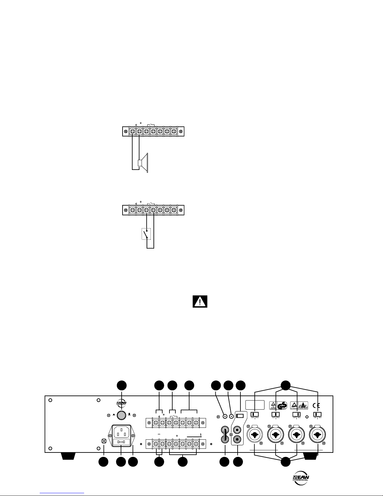
4. REAR PANEL FEATURES....................................................5
5. THERMAL CONSIDERATIONS ..........................................8
6. CONNECTIONS ...................................................................8
7. TYPICAL HOOKUP DIAGRAM...........................................9
8. SPECIFICATIONS..............................................................10
9. SERVICE INFORMATION .................................................11
10. EAW COMMERCIAL WARRANTY ................................11
D. The Component does not appear to operate normally or exhibits a
marked change in performance; or
E. The Component has been dropped, or its chassis damaged.
12. Servicing — The user should not attempt to service the Component
beyond those means described in this operating manual. All other
servicing should be referred to the EAW Commercial Service Department.
13. To prevent electric shock, do not use this polarized plug with an
extension cord, receptacle or other outlet unless the blades can be fully
inserted to prevent blade exposure.
Pour prévenir les chocs électriques ne pas utiliser cette che polariseé
avec un prolongateur, un prise de courant ou une autre sortie de
courant, sauf si les lames peuvent être insérées à fond sans laisser
aucune pariie à découvert.
14. Grounding or Polarization — Precautions should be taken so
that the grounding or polarization means of the DX-810 is not defeated.
15. This apparatus does not exceed the Class A/Class B (whichever is
applicable) limits for radio noise emissions from digital apparatus as set
out in the radio interference regulations of the Canadian Department of
Communications.
ATTENTION —Le présent appareil numérique n’émet pas de bruits
radioélectriques dépassant las limites applicables aux appareils
numériques de class A/de class B (selon le cas) prescrites dans le
règlement sur le brouillage radioélectrique édicté par les ministere des
communications du Canada.
WARNING! This equipment has been designed to be installed
by qualied professionals only! There are many factors to be
considered when installing professional sound reinforcement
systems, including mechanical and electrical considerations, as
well as acoustic coverage and performance. EAW Commercial
strongly recommends that this equipment be installed only by a
professional sound installer or contractor.
Part No. 0010169 Rev. A 02/04
© 2004 LOUD Technologies Inc. All Rights Reserved.
CAUTION AVIS
RISK OF ELECTRIC SHOCK • DO NOT OPEN
RISQUE DE CHOC ELECTRIQUE
NE PAS OUVRIR
CAUTION: TO REDUCE THE RISK OF ELECTRIC SHOCK
DO NOT REMOVE COVER (OR BACK)
NO USER-SERVICEABLE PARTS INSIDE
REFER SERVICING TO QUALIFIED PERSONNEL
ATTENTION: POUR EVITER LES RISQUES DE CHOC
ELECTRIQUE, NE PAS ENLEVER LE COUVERCLE. AUCUN
ENTRETIEN DE PIECES INTERIEURES PAR L'USAGER. CONFIER
L'ENTRETIEN AU PERSONNEL QUALIFIE.
AVIS: POUR EVITER LES RISQUES D'INCENDIE OU
D'ELECTROCUTION, N'EXPOSEZ PAS CET ARTICLE
A LA PLUIE OU A L'HUMIDITE
The lightning flash with arrowhead symbol within an equilateral triangle is
intended to alert the user to the presence of uninsulated "dangerous voltage"
within the product's enclosure, that may be of sufficient magnitude to constitute
a risk of electric shock to persons.
Le symbole éclair avec point de flèche à l'intérieur d'un triangle équilatéral est
utilisé pour alerter l'utilisateur de la présence à l'intérieur du coffret de "voltage
dangereux" non isolé d'ampleur suffisante pour constituer un risque d'éléctrocution.
The exclamation point within an equilateral triangle is intended to alert the user
of the presence of important operating and maintenance (servicing) instructions
in the literature accompanying the appliance.
Le point d'exclamation à l'intérieur d'un triangle équilatéral est employé pour
alerter les utilisateurs de la présence d'instructions importantes pour le fonction-
nement et l'entretien (service) dans le livret d'instruction accompagnant l'appareil.

2 – CAM150 / CAM60
CAM150 / CAM60 – 3
2. INTRODUCTION
The CAM150 and CAM60 Paging Ampliers are designed
for continuous duty in speech, music, paging and sound
reinforcement applications in churches, schools, ofces,
arenas, hotel meeting rooms, convention centers, recreation
facilities and other venues demanding high performance,
exible features and rugged dependability.
The CAM150 has a 150 watt power amplier, and the
CAM60 has 60 watts. Apart from this difference in power
output, the two models are identical in details and operation.
Four combination mic/line inputs are actively balanced,
with individual switchable sensitivity controls for line-level
input, mic-level input, and mic-level input with 24 VDC
phantom power.
Input 1 has voice-activated priority over Inputs 2-4 and the
AUX Input. Inputs 1-4 have switch-activated priority over the
Aux input. A Telephone Paging input is provided on a terminal
strip, with a rear panel volume control, and has voice-activated
priority over all the inputs. The voice-activated priority has an
internal adjustable level control.
The stereo unbalanced RCA Aux inputs are internally
summed to mono, and have an input sensitivity switch to
optimize the input for a CD player, tuner, tape player, or other
auxiliary input. A small speaker can be used to monitor the
auxiliary music program, and its volume adjustment is provided
with a small monitor trim control on the rear panel.
Output modes include 4 Ω constant impedance, and 25 V,
70 V, and 100 V constant voltage. The smart output stage
is fully protected against permanent damage caused by
overloading, shorts, and extreme temperatures. The CAM150
and CAM60 operate on either 115 or 230 VAC, 50/60Hz,
supplied by a detachable IEC power cord. A voltage selector
switch is accessable from the bottom panel. A rear panel
terminal strip connection is provided for connecting an external
24 VDC backup battery, with a rear panel DC power switch.
An unbalanced signal processing loop is provided on the
rear panel with RCA connectors.
The front panel provides level controls for each Mic/Line
input, Aux, and Master volume, as well as Bass and Treble. An
LED Meter indicates signal strength and output overload. The
Bass and Treble controls provide up to 10 dB of boost or cut at
100 Hz and 10 kHz respectively.
KEY FEATURES
• Four Combination 1/4-inch/XLR Mic/Line Inputs
• One Stereo Auxiliary Input
• One Telephone Paging Input with Volume Trim Control
• CAM150: 150 watt rms, convection cooled
• CAM60: 60 watt rms, convection cooled
• 4 Ω – 25 V – 70 V – 100 V Outputs
• Discrete component power amplier
• Switched 24V Phantom Power
• One Speaker Monitor Output with Volume Trim Control
• Signal Processing Loop
• Switchable 24 VDC Backup Power Input
• 2 RU Rack-Mounting Kit Included
APPLICATIONS
• Foreground/Background Music Systems
• Sound Reinforcement Systems
• Paging Systems
• Continuous-duty Applications

4 – CAM150 / CAM60
CAM150 / CAM60 – 5
3. FRONT PANEL FEATURES
1. INPUT LEVEL
These controls allow you to individually adjust the volume
level of each of the four balanced inputs, and the Aux
input. We recommend that you turn down the level controls
of any unused or little-used inputs.
2. EQ-LO
Turn this clockwise to boost the level of the low-frequency
range below 100 Hz. Turn it counter-clockwise to cut the
level. In the center position, there is no change in level.
The maximum boost and cut is 10 dB at 100 Hz.
3. EQ-HI
Turn this clockwise to boost the level of the high-frequency
range above 10 kHz. Turn it counter-clockwise to cut the
level. In the center position, there is no change in level.
The maximum boost and cut is 10 dB at 10 kHz.
4. MASTER VOLUME
Use this volume control to adjust the sound output level
to your speakers. Adjust the master level and the input
levels to average settings, not too high and not too low.
For example, if you nd you have to turn the master volume
up high, then the input level controls might be set too low.
If the master volume becomes loud after a small rotation,
then the input level controls might be set too high.
5. LED METER
This meter shows the signal level reaching the input
section of the main power amplier.
The lower eight LEDs represent the area between -20 dB
and 0 dB. Adjust the Master Volume to keep your output
within these levels.
Make sure the top two LEDs are not lit, or the outgoing
signal will clip and distort. Turn down the Master Volume
level so the top two LEDs do not light.
© 2004 LOUD TECHNOLOGIES INC.
"EAW" IS A REGISTERED TRADEMARK
OF LOUD TECHNOLOGIES INC.
CAM150-MIXER AMPLIFIER
6. POWER SWITCH
Use this switch to turn the unit on or off. The power is on
when the top of the switch is pressed, and off when the
bottom is pressed. Turn it off if you are not using the unit
for long periods of time.
1234
5
6

4 – CAM150 / CAM60
CAM150 / CAM60 – 5
4. REAR PANEL FEATURES
7. DC POWER SWITCH
If this switch is pressed in, the unit will automatically
switch to external DC battery power whenever (or if-ever)
your local AC power fails. You will need to connect an
external 24 Volt battery to the DC battery terminals (19).
If the switch is out, the battery will not power up the unit.
8. AUXILIARY SPEAKER TERMINALS
Use these terminals to connect
a small speaker to monitor the
AUX IN (16) Auxiliary input.
The unit has an internal 1 watt
amplier to power the speaker,
and you can control the volume
with the rear panel MONITOR
VOLUME (12) level control.
9. PRIORITY TERMINALS
If these terminals are
connected together using an
external switch, the AUX IN
(16) input is attenuated and
the other inputs have priority.
10. TELEPHONE PAGING TERMINALS
These 600 ohm input terminals allow you to connect an
auxiliary input. Any signals present at these terminals take
voice priority over all other inputs. The volume is adjusted
using the rear panel TEL VOL (11) level control.
For a balanced connection:
T = Tip (Hot or "+")
R = Ring (Cold or "–")
G = Ground (Shield)
For an unbalanced connection:
T = Tip (Hot or "+")
G = Ground (Shield)
© 2004 LOUD TECHNOLOGIES INC.
"EAW" IS A REGISTERED TRADEMARK
OF LOUD TECHNOLOGIES INC.
CAM150-MIXER AMPLIFIER
11. TELEPHONE PAGING VOLUME
This controls the volume of any signals connected to the
TELEPHONE PAGING (10) input terminals. Adjust it to suit
your taste, so any pages are heard clearly. Turn this down if
you are not using these input terminals.
12. MONITOR VOLUME
This control allows you to adjust the output level present at
the AUXILIARY SPEAKER TERMINALS (8).
13. AUX IN INPUT SENSITIVITY SELECTOR
This four-position slide switch lets you adjust the input
sensitivity of the AUX IN (16) to suit whatever source
device you have connected. The options are: CD, Tuner,
Tape, and Aux. Try each position, and nd which sounds
best.
14. INPUT SENSITIVITY and PHANTOM POWER
SELECTORS
These three-position slide switches allow you to adjust
each of the four inputs to suit whatever you are connecting.
The positions are LINE, MIC and PHANTOM 24V.
LINE: select this if you are connecting a line-level signal.
MIC: use this if you are connecting a dynamic microphone.
PHANTOM 24V: use this if you are connecting a
microphone which requires phantom power (such as
condenser mics). The unit will supply 24 VDC on XLR inputs
pin 2 and pin 3.
Consult your microphone's documentation to see if it
needs phantom power. Take care as some microphones
can be damaged. Also, never use phantom power if you
have connected a line input using the XLR inputs. Do not
plug or unplug any microphones with the phantom power
on; turn it off rst. Turn the front panel INPUT LEVEL
controls down before you turn the phantom power on.
19 18
22 17 16 15
14
13
8
7
20
12
11
21
10
9

6 – CAM150 / CAM60
CAM150 / CAM60 – 7
15. INPUTS
These inputs allow you to connect balanced XLR plugs
from microphones or 1/4" TRS or TS plugs from line-level
sources.
INPUT 1 has "Voice Priority" over the other inputs. If an
announcement is made using a microphone connected to
INPUT 1, then the other inputs are over-ridden.
16. AUX INPUTS
These left and right unbalanced RCA inputs allow you to
connect your audio sources, such as tuner, CD player, DVD
audio, tape deck, etc. They accept stereo line-level input
signals, and sum them to mono. This input is suitable for
connecting most common line-level sources. Use high-
quality, two-conductor shielded cable for the connections.
17. MAIN IN, PREAMP OUT
These two connections are normally joined using a U-shaped
jumper.
Note: If the U-shaped jumper is missing, then there will
be no output from your unit.
Use the PREAMP OUT to send a line-level signal to an
external amplier, or to an external processor or equalizer.
The output is affected by the Level controls, but not by the
Master Volume or Tone controls.
The output from an external processor can connect to
MAIN IN. The Master Volume and Tone controls will adjust
any signals before they reach the main amplier section.
18. OUTPUT TERMINALS
This terminal is normally covered by a protective cover.
Remove the two screws and the cover while making or
undoing connections. Securely ret the cover when you
have nished making the connections.
The ve output terminals are labeled COM, 4 Ω, 25 V, 70 V
and 100 V.
CONSTANT IMPEDANCE
To connect a speaker directly,
connect the COM terminal
to the negative post of your
speaker, and connect the 4 Ω
terminal to the positive post.
Make sure that your
average speaker impedance
is not less than 4 Ω, as this may
overload the amplier.
The speaker output connectors are screw terminals. Use 16
or 18 gauge wire for connecting the amplier outputs to the
speakers. Strip the wire back about 3/8" inch, loosen the
screw enough to loop the wire around the shaft of the screw
(clockwise), and tighten down the screw with a screwdriver.
CONSTANT VOLTAGE
If you are using a constant-voltage distributed speaker
system, connect either the 25 V, 70 V, or 100 V output terminal
to the "+" side of the speaker system, and connect the "COM"
output terminal to the "–" side of the speaker system.
The voltage of your speakers must equal the voltage of
the amplier's output terminal ( 25 V, 70 V, or 100 V).
Make sure that the taps on the speakers add up to no
more than 90% of the rated power for the amplier
being used CAM150: 135 watts, CAM60: 54 watts.
CAUTION: To prevent the risk of electric shock,
never touch the bare wires coming from the OUTPUT
TERMINALS of the amplier when it is switched on.
When the connections have been made, insulate the
25 V, 70 V, and 100 V terminals of the amplier using
the protective cover supplied.
© 2004 LOUD TECHNOLOGIES INC.
"EAW" IS A REGISTERED TRADEMARK
OF LOUD TECHNOLOGIES INC.
CAM150-MIXER AMPLIFIER
19 18
22 17 16 15
14
13
8
7
20
12
11
21
10
9
+ 100V70V 25V
4
COM
DC 24V
-
- +

6 – CAM150 / CAM60
CAM150 / CAM60 – 7
COM and 25V are used to connect a string of 25V speakers.
Use Class II or Class I wiring:
COM and 70V are used to connect 70V speakers.
Use Class I wiring:
COM and 100V are used to connect 100V speakers.
Use Class I wiring:
19. DC BATTERY TERMINALS
These two screw terminals are
used to connect an optional
external 24 VDC battery.
Make absolutely sure
the positive post of
your battery connects to the
positive terminal, and the
negative post connects to the
negative terminal. To minimize
the voltage drop across the
wires and prevent overheating, use at least 14 AWG
insulated wire.
+ 100V70V 25V
4
COM
DC 24V
-
0 0 0
25V 25V 25V
+ 100V70V 25V
4
COM
DC 24V
-
000
70V 70V 70V
+ 100V70V 25V
4
COM
DC 24V
-
0 0 0
100V 100V 100V
The unit can be powered using a 24 VDC power supply
(if the rear panel DC POWER SWITCH is pressed in). This
can serve as a backup supply in case of an AC power
failure. The unit seamlessly switches to the backup supply
if there's a power loss, allowing safety instructions and
emergency communications to continue. When both AC
power and 24 VDC power are connected, the AC power is
used and no current is drawn from the DC supply.
Note: The unit will not charge the battery, so you should
have a dedicated charging system. Note also, that when
running on DC power, the output is lower than when
running on AC power.
20. IEC AC INPUT
The supplied power cord connects here. Make sure
that your local AC Mains has the same voltage as your
unit, and is capable of supplying adequate current.
Voltage Conversion
The CAM150 and CAM60 can be congured to operate at
115 VAC or 230 VAC.
Be sure the VOLTAGE SELECTOR switch located on
the bottom panel is set to the correct position for
the AC power supply being used, before plugging in the
power cord. The switch can be moved with a small at
screwdriver, once the protective cover is removed. Replace
the cover afterwards.
21. AC FUSE
The fuse resides inside a little cover just below the AC
input.
Make sure that the power cord is unplugged before
removing the AC fuse. When you are sure that all is
safe, pry off the fuse cover with a at screwdriver, taking
care not to damage the cover or fuse. Replace the fuse only
with the same type and rating as marked on your unit.
22. GROUND (EARTH) SCREW
The chassis connects to ground via the AC ground, and
normally does not need any extra ground connection.
Connections, if required, should be made by experienced,
qualied electricians.
+ 100V70V 25V
4
COM
DC 24V
-
- +
24VDC

8 – CAM150 / CAM60
CAM150 / CAM60 – 9
2
2
31
1
SHIELD
COLD
HOT
SHIELD
COLD
HOT
3
SHIELD
COLD
HOT
3
2
1
SLEEVE
TIP
TIP
SLEEVE
TIP
SLEEVE
TI
P
SLEEVE
TIPSLEEVE
SLEEVE
TIP
SLEEVE
TIP
RING
RING
TIP
SLEEVERING
5. THERMAL CONSIDERATIONS
The power amplier within the unit is convection cooled
rather than fan cooled. Heat is drawn away from the
amplier by the heatsink and radiated through the cooling
vents in the top cover.
When installing, be sure to allow sufcient air space
around the top and rear of the amplier to allow
adequate cooling for the heatsink. Leave at least one rack
space above and below, and at least 6 inches behind the
chassis to allow proper ventilation.
If the amplier should overheat, a thermal switch turns
off the power amplier, allowing the heatsinks to cool
down. Once the amplier has cooled to a safe operating
temperature, the thermal switch resets and reactivates
the amplier. If this should occur, identify the cause of the
problem and take corrective action. For example:
• Provide better ventilation
• Install a fan in the rack to move more air
• Make sure the amplier is not overloaded with too
low of a load impedance or by a short circuit on the
speaker line
RACK MOUNTING
Two rack ears are provided to allow the unit to be tted
within a standard 19" rack.
Remove two front screws from each side, and securely t
each rack ear in place. The unit still needs to be supported
underneath, due to the weight of the power and output
transformers.
6. CONNECTIONS
Inputs 1 to 4 use a dual-purpose input connector which can
accept XLR and 1/4" TRS and TS plugs.
The AUX IN uses unbalanced RCA connectors, as does the
MAIN IN and PREAMP OUT.
XLR Connectors
Inputs 1 to 4 can accept 3-pin male XLR connectors, wired
as follows (according to standards specied by the Audio
Engineering Society):
XLR Balanced Wiring
Pin 1 = Shield
Pin 2 = Hot (+)
Pin 3 = Cold (–)
1/4" TRS Phone Plugs and Jacks
“TRS” stands for Tip-Ring-Sleeve, the three connections
available on a stereo 1/4" or balanced phone jack or plug.
TRS jacks and plugs are used for balanced signals and
stereo headphones.
1/4" TRS Balanced Mono wiring
Sleeve = Shield
Tip = Hot (+)
Ring = Cold (–)
1/4" TS Phone Plugs and Jacks
“TS” stands for Tip-Sleeve, the two connections available
on a mono 1/4" phone jack or plug. They are used for
unbalanced signals.
1/4" TS Unbalanced Wiring
Sleeve = Shield
Tip = Hot (+)
RCA Plugs and Jacks
RCA-type plugs (also known as phono plugs) and jacks
are often used in home stereo and video equipment and
in many other applications. They are unbalanced and
electrically equivalent to a 1/4" TS phone plug.
RCA Unbalanced Wiring
Sleeve = Shield
Tip = Hot

8 – CAM150 / CAM60
CAM150 / CAM60 – 9
7. TYPICAL HOOKUP DIAGRAM

10 – CAM150 / CAM60
CAM150 / CAM60 – 11
8. SPECIFICATIONS
Performance
CAM150 Amplier Power: 150 W, nominal, 200 W peak (10 mS)
CAM60 Amplier Power: 60 W, nominal, 90 W peak (10 mS)
Frequency Response: 50 Hz–15 kHz ±3 dB
Distortion: < 0.5% THD at 1 kHz nominal power
Noise: >60 dB below nominal power
Equalization
Output: EQ-HI: ±10 dB at 10 kHz
EQ-LO: ±10 dB at 100 Hz
Audio Inputs
Inputs 1-4 Type: Four balanced/unbalanced combination 1/4-inch/XLR
connectors with switchable input level and 24 VDC
phantom power
Inputs 1-4 Mic Sensitivity: –66 dBV balanced/–60 dBV unbalanced (0.5/1.0 mV)
Inputs 1-4 Line Sensitivity: –26 dBV balanced/–20 dBV unbalanced (50/200 mV)
Inputs 1-4 Mic Impedance: 600 Ω
Inputs 1-4 Line Impedance: 47 kΩ
Aux In Type: One pair unbalanced stereo RCA connectors
Aux In Sensitivity:
CD: –5 dBV (570 mV)
TUNER: –15 dBV (180 mV)
TAPE: –10 dBV (320 mV)
AUX: –20 dBV (100 mV)
Aux In Impedance:
CD: 80 kΩ
TUNER: 30 kΩ
TAPE: 50 kΩ
AUX: 20 kΩ
Tel/Paging Input Type: One balanced/unbalanced screw-terminal
connector with adjustable input level
Tel/Paging Input Impedance: 600 Ω
Main Input Type: One unbalanced RCA connector
Main Input Sensitivity: 0 dBV (1 V)
Main Input Impedance: 10 kΩ
Audio Outputs
Number of Channels: One
Low Impedance: 4 Ω
Constant Voltage: 25V, 70V, 100V Screw-terminal connectors
CAM150 (4.5 Ω, 32.5 Ω, 66.5 Ω)
CAM60 (10 Ω, 83 Ω, 170 Ω)
Pre Out: One unbalanced RCA line-level
output 1V/600 Ω
Monitor Out: One terminal strip connection 1 watt/8 Ω
Control Inputs and Outputs
Inputs: Priority switch input, dry contact closure
Screw-terminal connectors
Controls
Front Panel: Power switch, Master Volume, Inputs 1–4, Aux level,
EQ-HI (Treble shelving), EQ-LO (Bass shelving)
Rear Panel: Telephone output volume level, Input 1-4 Mic/Line/
Phantom switch, Monitor output volume level,
24 VDC on/off switch
AC Power
Power Supply: 115/230 VAC (±5%), 50/60 Hz, 2.5 A fuse
24 VDC battery: CAM150: 15 A fuse
CAM60: 8 A fuse
Power Consumption: CAM150: 345 W
CAM60: 132 W
Environment
Maximum Ambient: 131° F (55° C) Non-precipitating humidity
Physical
Dimensions (HxWxD): 3.9 in/100 mm x 17.1 in/435 mm x 13.2 in/335 mm
Weight: CAM150: 25.6 lb/11.6 kg
CAM60: 22.3 lb/10.1 kg
Warranty
5 years, parts and labor
Accessories
Rack-mount kit
DISCLAIMER
EAW Commercial continually engages in research related
to product improvement, new materials, and production
methods. Design renements are introduced into existing
products without notice as a routine expression of that
philosophy. For this reason, any current EAW Commercial
product may differ in some respect from its published
description, but will always equal or exceed the original design
specications unless otherwise stated.
“EAW Commercial” is a trademark of LOUD Technologies
Inc. All other brand names mentioned are trademarks or
registered trademarks of their respective holders, and are
hereby acknowledged.
VOICE PRIORITY ADJUSTMENT
The amplier has an internal adjustment potentiometer
(on the front circuit board) which allows you to set the level at
which the voice priority circuit activates.
For example, suppose that only loud talking into a paging
microphone (on Input 1) will mute the auxilliary music. This
pot can adjust the voice priority sensitivity until it takes only
moderate or low volumes to mute the aux music.
Please note that the following adjustment requires that
the top cover be removed, therefore this procedure
is for qualied and experienced electronics technicians
only, carefully trained in all aspects of ESD (electro-static
discharge) precautions and electronics safety.
1. Make sure the unit is switched off, and that the power
supply cord and all other cords are removed.
2. Undo the top cover screws and remove the top cover.
3. Look at the top edge of the front panel circuit board. Just
above the INPUT 2 Level control, you will see a small
potentiometer, VR102.
4. Using an insulated small phillips screwdriver, gently rotate
this pot to change the sensitivity (clockwise for more
sensitivity, i.e., less intense signals will mute the aux. The
pot can be reached from the top by passing the screwdriver
between the front panel top edge and the metal chassis.
5. The voice priority can also be disabled by removing the
small jumper next to the pot. You will need a good pair of
needle-nosed pliers, or remove the front panel circuit board
from the front panel by pulling off all the plastic knobs and
undoing the hex nuts on each level control.
6. When nished, recheck your work, and replace the top
cover. Verify that Input 1 or the Telephone paging suitably
mute the Aux and other inputs, without having to shout.

10 – CAM150 / CAM60
CAM150 / CAM60 – 11
9. SERVICE INFORMATION
In the event that your CAM150 or CAM60 should require
servicing, please follow these instructions:
1. Call EAW Commercial Tech Support at 1-888-337-7404,
7 am to 5 pm PST (Monday-Friday), to verify the problem
and obtain a Return Authorization (RA) Number. Be sure to
have the serial number of the unit when you call. You must
have a Return Authorization Number in order to obtain
warranty service at the factory or at an authorized service
center. You can also email EAW Commercial Tech Support
2. Pack the unit in its original packaging. THIS IS VERY
IMPORTANT. EAW Commercial is not responsible for
any damage that occurs during shipping due to non-
conventional packaging. Original packaging helps to
minimize the possibility of shipping damage.
3. Include a legible note stating your name, (no P.O. boxes),
daytime phone number, Return Authorization Number, and
a detailed description of the problem, including how we
can duplicate it.
4. Write the Return Authorization Number in BIG BOLD PRINT
on the top of the box.
5. Tech Support will tell you where to ship the unit when you
call for an RA Number. We suggest insurance for all forms
of cartage.
10. EAW COMMERCIAL
WARRANTY
Warranty: LOUD Technologies Inc. requires its authorized
EAW Commercial distributors to abide by the following
warranty terms for all EAW Commercial brand products
(all dates are from the date of delivery from an Authorized
EAW Commercial Distributor to the end user/installation
site): Loudspeakers – 5 years; Active Electronics – 5 years;
Accessories – 2 years.
What Is Covered: Defects in workmanship and materials
and against malfunctions. EAW Commercial distributors
must remedy all such defects and malfunctions without
charge for parts or labor if the warranty applies. Final
determination of warranty coverage lies solely with each
authorized EAW Commercial distributor.
What Is Not Covered: This warranty does not extend
to damage or malfunctions resulting from, but not limited
to, shipment, improper installation, misuse, neglect,
abuse, normal wear, accident, or to any product on
which the serial number has been modied or removed.
Exterior defects in or damage to the exterior appearance
are specically excluded from this warranty. EAW
Commercial distributors shall not be liable for incidental
or consequential damages resulting from the use of EAW
Commercial products. Repairs and/or modications by
other than an Authorized EAW Commercial Distributor
automatically voids this warranty.
L
R
LINE/MIC
SWITCH
24V
POWER
PHANTOM
SWITCH
POWER
PHANTOM
SWITCH
POWER
PHANTOM
SWITCH
LINE/MIC
SWITCH
24V
POWER
PHANTOM
SWITCH
EXTERNA
L
PRIORITY
SWITCH
1 WATT
SPEAKER
LINE/MIC
SWITCH
AUX
SELECTOR
24V
INPUT 1
INPUT 2
INPUT 3
INPUT 4
AUX INPUT
TEL PAGING
INPUTS
INPUT 1
VOLUME
PRE OUT/
MAIN IN
BASS TREBLE
LED
METER
MASTER
VOLUME
MAIN
POWER
AMPLIFIER
24 VDC TERMINALS
AC INPUT
AC FUSE AC SWITCH
POWER
TRANSFORMER
OUTPUT
TRANSFORMER
DC RAIL
DC SWITCH
1 WATT
AMPLIFIER
MONITOR
VOLUME
AUX
MUTE
VOICE
PRIORITY
MUTE
THRESHOLD
INPUT 2
VOLUME
INPUT 2
VOLUME
INPUT 4
VOLUME
AUX
VOLUME
TEL PAGING
VOLUME
LINE/MIC
SWITCH
24V
100V
70V
25V
4 ohm
COM
BLOCK DIAGRAM

EAW Commercial A LOUD Technologies Inc. Company
EAW Commercial | One Main Street | Whitinsville, MA 01588 USA | TEL toll free within US/Canada 888.337.7404
TEL outside US 425.892.6503 | FAX 425.485.1152 | www.eawcommercial.com
© 2004 LOUD Technologies Inc. All Rights Reserved.
Other manuals for CAM150
1
This manual suits for next models
1
Table of contents
Other EAW Amplifier manuals