Page 3/21
Table of contents:
FOR YOUR OWN SAFETY.....................................................................................................4
All about accessories ...........................................................................................................5
General information ............................................................................................................5
•PIN code ..................................................................................................................5
Transmission safety ............................................................................................................5
•Data coding ..............................................................................................................5
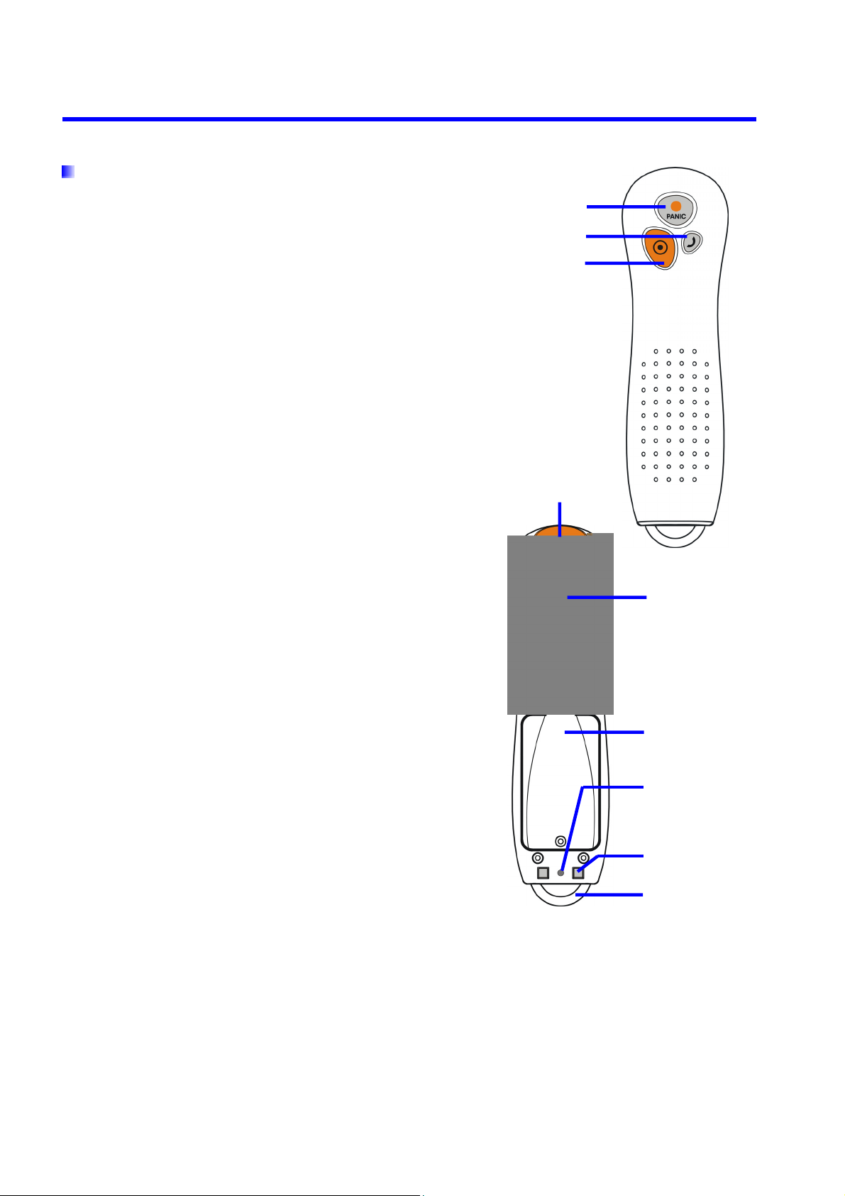
Functions review.................................................................................................................6
•RF-ID transponders reader.........................................................................................6
•Controlling buttons....................................................................................................6
•Work mode indicator .................................................................................................6
•Loudspeaker and microphone.....................................................................................6
•Clock........................................................................................................................6
•Memory....................................................................................................................6
•GPRS service (General Packet Radio Service)...............................................................6
•Before using GPRS technology ...................................................................................6
•GPRS service charges ................................................................................................6
1. A few words about the device ..........................................................................................7
2. First steps ......................................................................................................................8
•SIM card and battery installation ................................................................................8
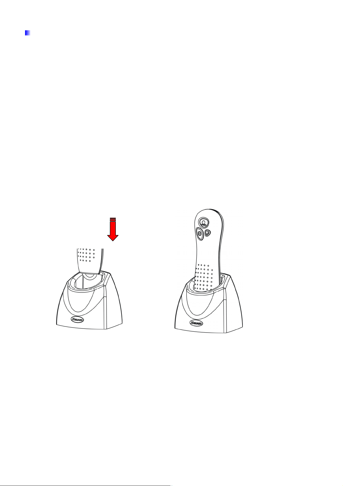
•Battery charging ..................................................................................................... 10
3. Configuration................................................................................................................11
4. Controlling commands ................................................................................................... 12
5. Operation rules .............................................................................................................13
•RF-ID transponder read-out ..................................................................................... 13
•Sending „Panic” command ....................................................................................... 13
•Sending „Call me” command .................................................................................... 14
•Voice connection..................................................................................................... 14
•Checking GSM range ............................................................................................... 14
6. Indicating work mode.................................................................................................... 15
•Normal work mode.................................................................................................. 15
•RF-ID transponder read-out ..................................................................................... 15
•GSM range ............................................................................................................. 16
•Data transmission ................................................................................................... 16
•Registration at GSM network .................................................................................... 16
•Battery low ............................................................................................................. 17
•Battery charging ..................................................................................................... 17
•Battery full ............................................................................................................. 17
•Battery empty......................................................................................................... 18
•System general error ............................................................................................... 18
7. Information about batteries ........................................................................................... 19
•Battery charging and discharging ............................................................................. 19
8. Operation and maintenance ........................................................................................... 20
9. Exemplary implementation............................................................................................. 20
10. Technical parameters .................................................................................................. 21