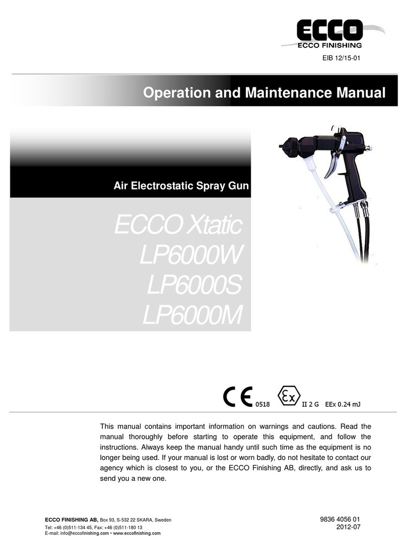
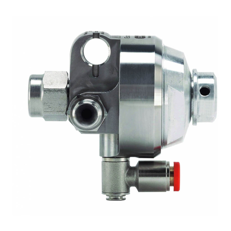
Ecco 70AP Guide

Designation system:
70 A P
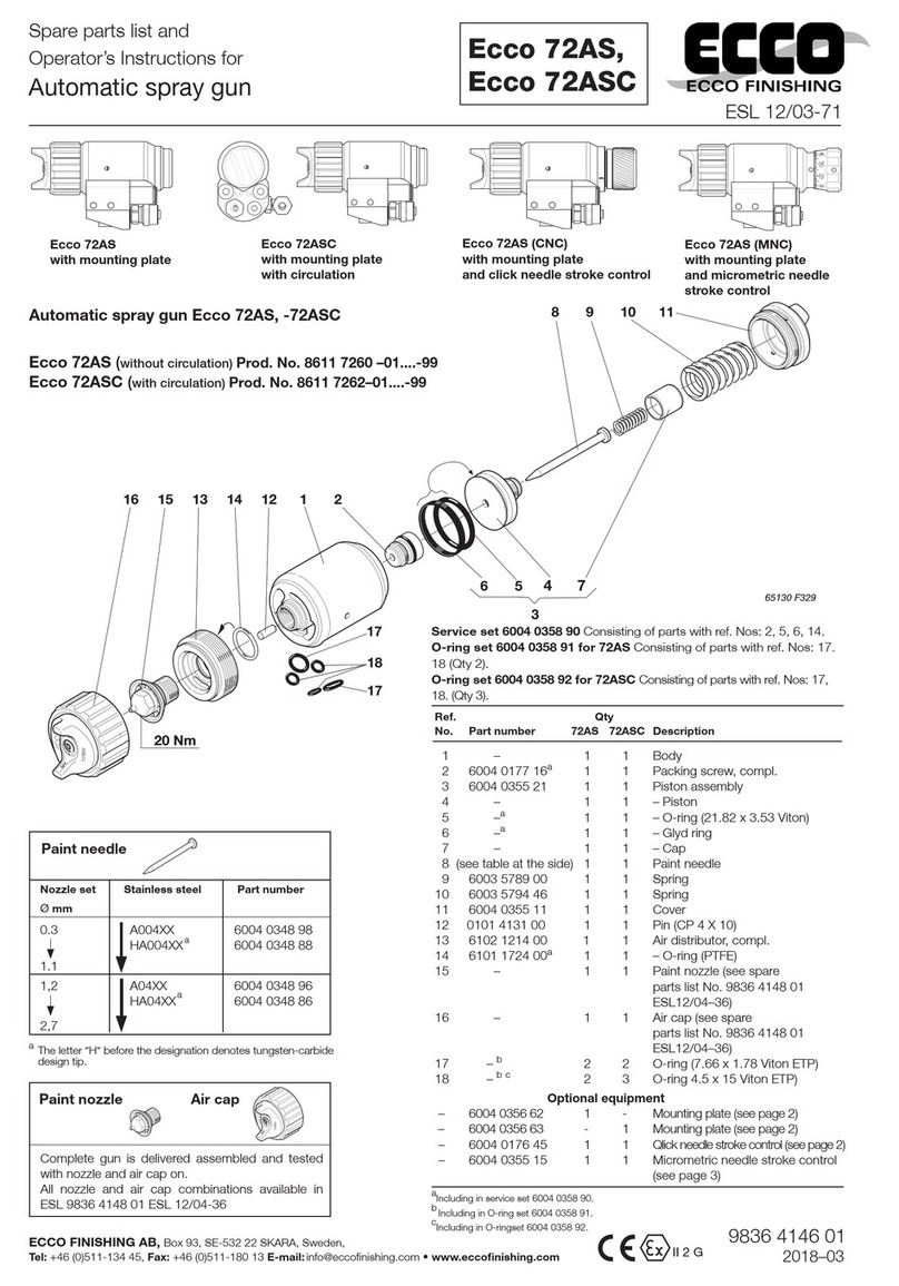
Ref.
No. Part number Qty Description
1 6003 9523 00 1 Cover cap
2 6101 5626 14 1 Plug (G1/4)
3 6003 9770 02 1 Cap
4 6003 5794 46 1 Spring (SS)
5 6003 5790 00d1 Screw (AL)
6 6003 5789 00 1 Spring
7 (see page 3) 1 Paint needle
8 6003 5796 77 1 Piston (UHMW)
9 6103 3112 71a1 Packing screw (UHMV-PE))
10 0211 1962 75b4 Screw (MC6S 5 x 10 A2)
11 6003 9770 03 1 Cylinder house
12 0663 9051 80a1 O-ring (7.65 x 2.0 PF)
13 6004 0174 10 1 Body (SS)
14 6000 8369 00a2 Packing screw
15 6804 0020 46a8 Plug
16 0663 9051 70a3 O-ring (7.66 x 1.78 PF)
17 0663 9051 48a1 Ring (4.8/9.0 x 2 PF128)
18 0101 4131 00a3 Pin
19 6103 3131 00a1 Packing screw (SS/HD500)
20 6102 1215 91 1 Distribution ring H
20a 6101 1724 00 1 - O-ring
20 6102 1215 92 1 Distribution ring V
20a 6101 1724 00 1 - O-ring
aIncluding in service set / bTorque 6.6 Nm / cTorque 22 Nm /dLoctite 574.
Service set 6004 0018 20 Consisting of parts with ref. Nos.
9, 12, 14 (Qty 2), 15(Qty 6), 16 (Qty 3), 19, 20a.
Ref.
No. Part number Qty Description
Service set 6004 0019 20 Consisting of parts with ref. Nos. 16 (Qty 3),
17, 18 (Qty 2).
Ecco 70AP................. Prod. No. 8611 6174 00–99
Parts without bold designate part number are not supplied separately.
65130 F267
65130 F250-4
65130 F250-3
P = Purge
A = Automatic
70 = Type
Spare parts list and
Operator’s Instructions for
Automatic Spray Gun
ECCO
ECCO FINISHING
ESL 12/03-12
Ecco 70AP
II 2 G
ECCO FINISHING AB, Box 93, S-532 22 SKARA, Sweden
Tel: +46 (0)511-134 45, Fax: +46 (0)511-180 13
E-mail: info@eccofinishing.com • www.eccofinishing.com
9836 3238 01
2014–07
30 Nm
21 (see page 3)c1 Paint nozzle
23 (see page 3) 1 Air cap
24 6101 6065 99 1 Protection (POM)
25 0211 1960 77b2 Screw (MC6S M5 x 50 A4)
Optional equipment
26 6004 0022 00 1 Sensor, compl.
27 6804 0021 00 1 – Sensor (length 2m)
28 – 1 – Coupling (G1/4)
29 – 2m – Cabel protection
30 6004 0022 10 1 Sensor, compl. (for robot ABB)
31 6804 0021 00 1 – Sensor (length 2m)
32 6004 0021 21 1 – Nut
33 6004 0021 19 1 – Nipple
34 – 2m – Cabel protection
35 6004 0021 13 1 – Ring
36 6004 0021 15 1 – Nipple
37 6004 0021 23 1 – Plug
– 6003 9865 12 1 Wrench 12 mm (for paint nozzle)
– 6003 9865 14 1 Screw driver (for front packing screw)
– 6003 9865 32 1 Assembling tool (for piston)
– 6003 9865 36 1 Assembling tool (for distribution ring)

2
Optional equipment
6003 9770 00 Mounting plate, compl. for Spraymate
STL-HN – Operating air
F – Paint
ZL – Atomizing air
HL – Fan air
RF – Return paint
6004 0099 00 Gun adapter for Robot
65130 F264
6004 0099 50 Gun adapter with flush valve, compl.
for Robot
Ref.
No. Part number Qty Description
1 6004 0099 55 1 Adapter
2 6004 0099 54 1 – Plug
3 6004 0099 53 1 Piston
4 0663 9051 99 1 O-ring (23.0 x 2 PF128)
5 0663 9051 98 1 O-ring (4.0 x 2 PF128)
6 0663 9051 97 1 O-ring (1.78 x 1.78 PF128)
7 6004 0099 59 1 Spring
8 6004 0099 51 1 Cover
9 6803 9944 00 2 Screw (M4 x 8)
Ref.
No. Part number Qty Description
1 6004 0099 00 1 Adapter
2 6004 0099 54 1 – Plug
Qty
Ref. 6003 9770
No. Part number 20 35 Description
1 – 1 1 Mounting plate
2 0686 6101 47 1 1 Plug (G 1/8 SS)
3 6003 9820 41 2 2 Coupling (G 1/8-8 mm)
4 6003 9820 31 1 1 Coupling (G 1/8-6 mm)
5 6003 9827 95 1 - Coupling (G 1/8-6 mm)
6 6004 0225 59 - 1 Coupling SS (G 1/8-4 mm)
Optional equipment
7 6003 9770 51 1 1 Nipple (G 1/8 x G 3/8 SS)
8 6003 9770 52 1 1 Nipple (G 1/8 ø 8-6 mm SS)
9 6003 9770 53 1 1 Nipple (G 1/8 ø 10-8 mm SS)
65130 F279
Ref.
No. Part number Qty Description
1 – 1 Mounting plate
2 6003 9827 95 2 Coupling (G 1/8-6 mm)
3 6003 9827 93 2 Coupling (G 1/8-8 mm)
4 6003 9827 41 1 Elbow (G 1/8-8 mm)
6003 9770 20 Mounting plate, compl. for Robot
6003 9770 35 Mounting plate with stainless steel
paint coupling, compl. for Robot
STL-HN – Operating air
F – Paint
ZL – Atomizing air
HL – Fan air
RF – Return paint
65130 F280
65130 F265

3
T297 Fix 2 6004 0297 72
T297 Fix 4 6004 0297 74
T278 Fix 2 6102 3991 72
T278 Fix 4 6102 3991 74
A00470 6003 5786 98
HA00470 6003 6563 98
0.3 0.3 C 6001 1711 70
0.5 0.5 C 6001 1295 70
0.8 B0.8 C 6001 0966 70
1.1 1.1 C 6001 1068 70
6004 0218 92
Orifice
diameter
mm Designation Part number Part number Designation Part number Designation Part number
Nozzle combinations
Paint nozzle Purge insert Paint needle Air cap
A0470 6003 5786 96
HA0470 6003 6563 96
HA0470FP 6004 0219 66
1.2 G1.2 C 6003 9212 70
1.4 G1.4 C 6003 9214 70
1.6 G1.6 C 6003 9216 70
1.8 G1.8 C 6003 9218 70
1.4 F1.4 C 6004 0114 70
1.4 G1.4 C 6003 9214 70 HA130470 6004 0030 70
6004 0218 94
1.2 F1.2 C 6004 0112 70
1.4 F1.4 C 6004 0114 70
1.6 F1.6 C 6004 0116 70
Paint nozzle designation
The letter “C” after the designation denotes certified and controlled nozzle.
Paint needle designation
The letter ”H” before the designation denotes tungsten-carbide design.
The letter ”HA13” before the designation denotes cylindrical point (self cleaning tip) only for nozzle 1.4.
The letter ”FP” after the designation denotes double cut tip.
Air cap designation
The letter “C” after the designation denotes certified and controlled nozzle.
The letter “Fix 2” after the denotes rotary air cap 2 x 180overtical or horizontal spray pattern.
The letter “Fix 4” after the designation denotes rotary air cap 4 x 90o.
6004 0093 00
Flow control unit
for paint return
65130 F255
65130 F309
6003 9770 43 Mounting plate, compl.
for Robot with 13 mm guide pin
STL – Operating air
F – Paint
ZL – Atomizing air
HL – Fan air
Ref.
No. Part number Qty Description
1 – 1 Mounting plate
2 6003 9820 41 2 Coupling (G 1/8-8 mm)
3 6003 9820 31 1 Coupling (G 1/8-6 mm)
4 0194 1319 00 2 Set screw (SK6SS 8 x 10)
5 6003 9770 52 1 Nipple (G 1/8 8-mm SS)

4
Automatic air spray guns used for spraying of paint
under low pressure.
Principal data
Type Max. working Max. flushing Min/.max. air
paint pressure pressure operation pressure
Ecco bar bar bar
70AP 10 20 6/10
Important
Do not use halogenated hydrocarbons in coating application
equipment where aluminium or galvanized parts come
in contact with the solvent or coating material.
Halogenated hydrocarbons e.g. 1,1,1-thrichloroethane and
methylene chloride react, violently with such parts, causing
corrosion and danger for explosion.
WARNING
WARNING
Automatic spray gun Ecco 70AP with mounting plate 6003 9770 20 for robot,
mounting plate 6003 9770 00 for spraymate and connection plate 6003 9770 15
for paint circulation
All parts for the gun has been tested and certified for
optimum performance and can only be replaced with
genuine spare parts to maintain the total performance.
Before starting, read through all instructions carefully.
Operators instructions
65130 F251-01
Meassurements in millimetres
The high velocity flow of air and liquids through hoses and
nozzles may develop static electricity. Be sure that the equ-
ipment, object being sprayed, spraybooth, paint and waste
container are properly grounded to prevent static discharge
or sparks.

Fig. 2
Connections
For gun with mounting plate 6003 9770 20 for Robot
For gun with mounting plate 6003 9770 35 for Robot
65130 F254-1
5
Operation
•Install and operate the spray gun according to Fig.1, 2, 3 and 3.
•Blow the paint and air hoses clean before connection.
•Check that all connections are tight .
•Keep the spray gun clean and lubricate (waterfree vaseline)
moving parts at regular intervals.
•Lubricants for surface-treatment equipment must not contain
silicon.
• For short standstill periods, for instance over a night, it will
suffice to clean the air and paint nozzles on the outside. If a
two-component paint is used, however, the gun must be flushed
through immediately with solvent. This must also be done if the
gun is to remain unused for a longer period of time.
•When cleaning the air cap and the paint nozzle, use a soft
brush dipped in clean solvent. Do not place the entire gun in
solvent, as the oil on the lubricated parts would be dissolved. Blow
the air cap dry with comressed air from both sides.
•Never use iron or steel wire to clean air holes and ducts in
the nozzles.
•When assessing the reaction time of the connected spray
gun (the time from the start impulse until spraying commen-
ces) the reaction time of the control valve must be taken into
consideration.
• Rec om mend size for control valve:
– Control valve, 3-way, G 1/4. Min. flow area 28 mm2.
Mechanically, pneumatically or electrically actuated.
As the equipment works under pressure the utmost care must
be observed during the work. Bearing this in mind, never aim
the spray gun at a person or towards any part of the body. In
the event of personal injury caused by the spraying pressure,
immediate medical attention is essential. Before carrying out
any adjustment or repair, the equipment must be switched off
and the paint pressure relieved.
WARNING
How to operate
Note:
Valve orifice inside three-way solenoid valve should be minimum
ø 4 mm and also operating air hose length should be within 10 m
with the inner diameter more than ø 6 mm to avoid delayed
operation and any kind of failure.
Recommended paint viscosity differs according to paint properties
and painting conditions. 15 to 23 sec./Ford cup 4 is recommendable.
The gun is operate at low air pressure, high transfer efficiency will not
be obtained if the spray distance is to far.
Set the spray distance from the gun to the work piece as near as possible
within the range of 150-300 mm.
Paint spraying
Inhalation of paint, paint dust and solvent is not healthy. Make
sure an approved spraybooth is used. The operator must use
personal protection-breathing mask or fresh air hood.
CAUTION
Fig. 1 65130 F253-1
Connections (See Fig.1, 2, 3 and 4)
STL-HN (Fig.1 ) Operation air.
Coupling for tube ø 6/8 mm.
STL-HN (Fig.2 ) Operation air.
Coupling for tube ø 4/6 mm.
STL (Fig.3 ) Operation air.
Coupling for tube ø 4/6 mm.
F Paint. Coupling for tube ø 6/8 mm / ø 2.5/4 mm
for mounting plate 6003 9770 35
ZL Atomizing air.
Coupling for tube ø 6/8 mm.
HL Fan air.
Coupling for tube ø 6/8 mm.
RF (Fig.1) Return paint.
Coupling for tube ø 6/8 mm.
RF (Fig.2) Return paint.
Plug G 1/8.
RF (Fig.4) Return paint.
Coupling for tube ø 4/6 mm.
65130 F309-2
Connections
For gun with mounting plate 6003 9770 43 for Robot
with 13 mm guide pin
Fig. 3
Fig. 4
Connections
For gun with connection plate 6003 9770 15
for paint circulation
65130 F256
Connections
For gun with mounting plate 6003 9770 00 for Spraymate

6
Fig. 7
Automatic spray guns Ecco 70AP
Fig. 5
The position of guide pin for Horizontal Pattern
Fig. 6
The position of guide pin for Vertical Pattern
Air caps (See Fig. 5 and 6)
The air caps are tested and certified according to the SEAVA meth-
od. This gives a ”finger print” of the spray pattern on each air cap.
For further information please contact your supplier.
The retaining ring for the air cap shall only be tightened with hand force.
No tools are required. Especially important when a cap cleaner is used.
Fix 2 on the air cap, denotes that the air cap can be installed in ver-
tical or horizontal position, depending on the position of the pin in the
distribution ring (See Fig. 5 and 6).
Fix 4 on the air cap, denotes that the air cap can be installed in ver-
tical or horizontal position, regardless off the position of the pin in the
distribution ring.
Air caps can be sent back for checking and comparity the
performance. For further interesting please contact your supplier.
65130 F257
65130 F258
7. Paint needle
8. Piston
9. Packing screw
22. Paint nozzle
23. Air cap
19. Packing screw
20. Distribution ring
21. Purge insert
65130 F266

7
Disassembly - Reassembly (See Fig. page 1)
Changing the spray gun
1. Shut off the air and material feeds to the gun.
2. Depressurize the circuits.
3. Remove the 2 screws (25).
4. Take out the gun.
5. Fit the replacement gun and change the seals (16 and 17).
6. Re-fit the 2 screws (25).
Needle packing and needle
1. Unscrew the cap (3) and remove the spring (4).
2. Hold the entire needle and piston (8) and pull it towards the back.
3. Unscrew the screw (5) from the piston (8) and remove the spring (6)
and paint needle (7).
4. Remove the air cap (23), the paint nozzle (22) and the insert (21).
5. Remove the packing screw (19).
6. Clean everything well with cleaning agent and then blow out with air.
7. Re-fit the packing screw (19).
8. Re-fit the needle and piston assembly .
9. Re-fit the spring (4) and the cap (3).
10. Re-fit the insert (21), the paint nozzle (22) (screwing torque 30 Nm)
and the air cap (23) by hand.
Before any intervention on the spray gun, shot off the compressed
air supply and depressurize the by controlling the opening of
the spray gun.
VARNING
Before reassembling the different components:
• Clean the parts with the appropriate cleaning agent by means
of brush.
• Install new seals after having lubricated them with PTFE grease.
• Install new parts if necessary.
Troubleshooting
Introduction
Always commence troubleshooting by checking the general condition
of the spray gun. This can most easily be determined by test spraying,
which provides an opportunity for checking the spray pattern and capacity,
air leakage and gasket leakage.
Types of problems
Collection of information which makes it possible to identify the error
symptoms applicable to the spray gun in the event of malfunctioning
is a matter of vital importance. Identification of symptoms makes it possible
to decide whether the spray gun itself is the direct cause of the malfunc-
tioning or if this may have been caused by an external factor.
The following external factors can cause malfunctioning and should be
thoroughly checked:
1. The quality of the air, i.e. content of moisture, dirt particles and oil.
2. The quality of the paint, i.e. its viscosity, purity. etc.
3 The air and paint pressure in relation to viscosity of the paint and
nozzle combination used.
4. The size of the air/paint hoses.
Troubleshooting chart (See page 8)
Distribution ring
1. Remove the air cap (23) and the paint nozzle (22).
2. Remove the distribution ring (20) by screwing on the air cap (23) a
few turns. Withdraw the distribution ring axially from the body (13).
3. Re-fit the distribution ring (20) by mating it with a guide pin in
the body (13).
4. Re-fit the paint nozzle (22) (with torque 30 Nm) and re-fit the air cap
(23) (tighten by hand).

a) Dried paint on holes for atomizing air.
Clean the air holes, use appropriate clean-
ing agent and a soft brush.
b) Damage to holes for atomizing air.
Replace the air cap with a new one.
c) Air cap not sufficiently tightened.
Tighten the air cap properly by hand.
Troubleshoouting chart
Asymmetrical to the left or
to the right
a) Dried paint on holes for atomizing air.
b) Damage to holes for atomizing air.
c) Air cap not sufficiently tightened.
Distorted in the middle
a) Damage to the tip of the paint nozzle.
b) The pressure of the atomizing air in relation
to the viscosity of the paint.
a) Fit a new paint nozzle.
b) Adjust the air pressure of the atomizing air.
Spray Pattern Cause Remedy
Narrowing off in the middle
a) Wrong nozzle combination.
b) Fan air pressurer too high.
c) Paint viscosity unsuitable.
d) Incorrect spray angle.
a) Select a new nozzle combination suitable
for the viscosity of paint.
b) Reduce the pressure of the fan air.
c) Adjust the viscosity of the paint.
d) Adjust the angle with the fan width control.
Irregular spray (spitting)
a) Paint needle gasket leaky.
b) Damaged O-ring in distributor ring.
c) Paint nozzle not tightened.
d) Dirt on sealing surfaces of paint nozzle and
distributor ring.
e) Paint hose connection not tightened.
f) Paint hose defective.
a) Adjust the packing screws. If this does not
suffice, change the paint needle gaskets.
b) Change the O-ring in the distributor ring.
c) Tighten the paint nozzle.
d) Clean the sealing surfaces of the paint
nozzle and distributor ring with solvent and
blow clean.
e) Tighten the paint hose connection.
f) Change the paint hose.
Correct Spray Pattern
Paint leaking through the draining hole
(See Fig. 8 below).
Worn needle packing screw and/or needle. Replace damaged parts with new ones.
Air leaking through the draining hole
when the piston (8) is operating.
Worn or damaged packings (9) (12). Replace damaged parts with new ones.
Paint leaking through the paint nozzle
when the gun is closed.
Pollution between the needle and the nozzle
or needle and nozzle worn or damaged.
Unscrew air cap (23) and nozzle (22 screw)
Clean carefully and check for any sign of
damages or wear.
Paint leaking - Air leaking Cause Remedy
Fig. 8
Draining hole
65130 F289
This manual suits for next models
1
Table of contents
Other Ecco Paint Sprayer manuals